Replacing capacitors in the power supply. How to resolder capacitors yourself
If your computer freezes, works with errors, Windows does not install. If the computer does not start at all, or once it starts, it immediately stops, do not be too lazy to open the cover of the system unit and the problem may be visible to the naked eye - this is electrolytic capacitors for motherboard . One of the most common causes of motherboard failure is breakdown, short-circuiting or leakage of electrolytic capacitors. The filter capacitors in the processor voltage regulator or north bridge usually fail.
 Typically, faulty capacitors can be detected by a swollen rear part of the case or leaked electrolyte, but not necessarily. It happens that the capacitor is absolutely normal in appearance, but it is also not working properly. Rough check of the electrolytic capacitor without external damage, can be done using a dial ohmmeter by throwing the arrow. To check the capacitor, the ohmmeter is placed at the lowest range of resistance measurement and connected to the terminals of the capacitor; in the initial period, the capacitor will begin to charge and the instrument needle will deflect, and then as it charges, it will return to its place. You can repeat the test by changing the terminals of the capacitor. The more and slower the needle deviates, the greater the capacitance of the capacitor. If the ohmmeter shows zero, then the capacitor is shorted, and if it is infinity, then a break is likely. If, as the arrow returns to initial position it stops at some position without returning to its original position, then the capacitor is also faulty.
 To approximately determine the capacitance of a capacitor, you can compare the behavior of the instrument needle when connecting a known-good capacitor of the same capacity and the one being tested. To avoid damaging the device, it is necessary to discharge the capacitor by short-circuiting its terminals. Sometimes the condition of the capacitor can be determined with an ohmmeter without unsoldering it, if it is not bypassed by other elements of the circuit, but for a quality check it is still better to unsolder it. You can desolder and solder capacitors with any soldering iron of not very high power (up to 65 watts) using rosin or other soldering flux. After desoldering the capacitors, you need to clear the solder from the holes. I do this using a regular sewing needle, applying the tip of the needle to the hole on the side where the capacitor housings are located and at the same time the tip of the soldering iron on the other side.
The capacitance of the capacitors does not have to be selected exactly; it is possible with a deviation in any direction of up to 30% or even more. If the capacity of the existing capacitors is significantly smaller, then you can add another one; in processor stabilizer filters they are connected in parallel and there are free ones, reserve places. In no case should the voltage rating of the capacitors be chosen less than before. You should pay attention to the temperature rating, it should be 105 0 C. Polarity must be observed. If, having soldered the capacitors, you do not remember how they were positioned, then look carefully at how the others are located and solder them in the same way. When selecting capacitors to replace those located near the processor, it is necessary to take into account the cooler radiator so that they do not interfere with installing it in place. If you do not have the opportunity or desire to replace capacitors, then contact specialists who can do it efficiently and without problems. Typically, the cost of such repairs does not exceed 50% of the cost of the motherboard. Although, most likely no one will give you a guarantee in this case. It's up to you to decide whether to repair or replace?
Electrolytic capacitors- variety capacitors, in which the dielectric between the plates is a metal oxide film at the interface of the metal and electrolyte. This oxide is produced by electrochemical anodization, which ensures high uniformity of the insulating layer.
Over time, the electrolyte dries out and the capacitor loses its capacity; in most cases, the failure of the capacitor can be assessed by appearance. The capacitor swells at the top, where it has a special stamping.
The lower part, where the legs come out, may also inflate. Or the contents of the capacitor may leak.
Characteristic signs of problematic capacitors may include: spontaneous shutdowns computer, monitor, TV and other equipment. At first, this may only appear under load, for example when running a resource-demanding game.
To independently replace the capacitors in a switching power supply, you do not need any special skills or tools. In principle, nothing else is needed except a soldering iron, screwdriver and wire cutters.
We will show the replacement of capacitors using the example of repair pulse block PC-ATX power supply:

Unscrew the 4 screws and remove the power supply cover:

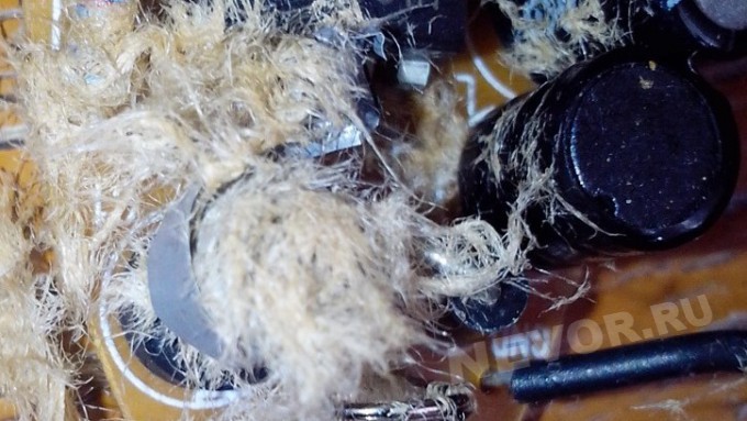
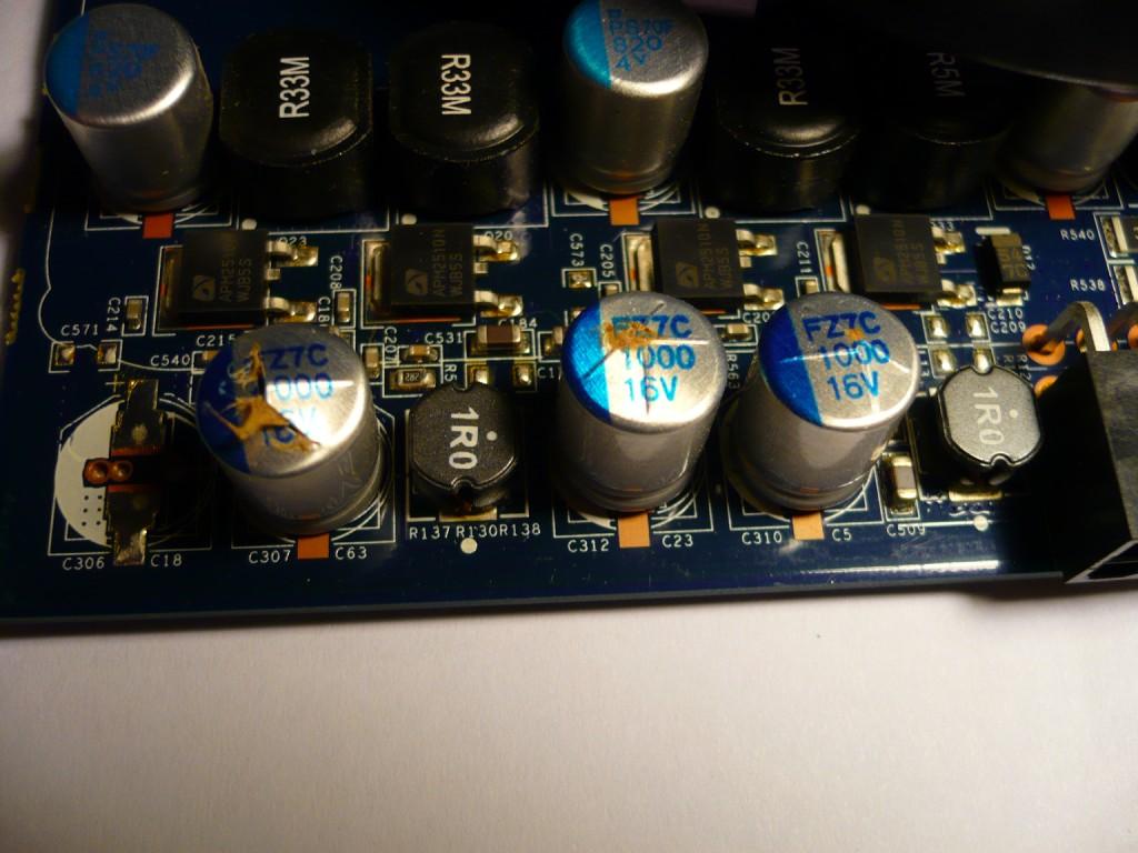
We look at the swollen capacitors and write down their capacity and voltage - these are the main parameters for purchasing new capacitors:


For example, we replaced 1000 µF capacitors for 10V and 16V. It is possible to replace a capacitor with a voltage of 10V to 16V, but vice versa it is not possible, i.e. the tension can only get higher. However, today you can buy any capacitor; until 2000, you had to use what you had.
Soldering the capacitors:


Most likely, when purchasing new capacitors, especially when replacing them in the motherboard, you will be asked the question: “Is it simple for you or for motherboards?”
How do computer capacitors differ from ordinary ones?
Until recently, there was no clear definition of a low ESR capacitor.
Standards such as JIS5141 and EIA395 only address capacitor test procedures.
The lack of standards has forced individual manufacturers to independently define what a low ESR capacitor means.
As a result, most suppliers have established a consensus criterion defining such capacitors as those that:
- service life is longer than that of standard capacitors;
- the maximum impedance is set at a frequency of 100 kHz and remains unchanged in the temperature range +20...-10°C;
- pulsating current is determined at a frequency of 100 kHz;
- increased temperature stability (temperature impedance coefficient).
The cost of such capacitors is about 4-6 UAH, i.e. the cost of repairs will be a pittance.
We solder in new capacitors, observing polarity:

We turn on and check the power supply, everything works.
Hardware failures can manifest themselves in different ways: computer crashes, artifacts on the screen, input/output errors when accessing the hard drive. Usually you try to solve the problem by installing new drivers, adjusting hardware parameters in the operating system, adjusting BIOS options, or, if all else fails, replacing components such as memory. But what to do if all this does not lead to the desired result?
Unfortunately, not only can it fail operating system or device drivers. And even purchasing the latest components, such as quad-core processors and terabyte hard disks, cannot prevent hardware failures. Hardware manufacturers usually determine the lifespan of each component of a computer or laptop. For hard drives This is typically five years, but other components may last longer. Key components such as processors, memory, motherboard or video card usually last significantly longer. If, of course, the operating and cooling conditions are normal. But it is impossible to predict how long this or that component will actually last.
One of the reasons for the strange behavior of a computer may be failed electrolytic capacitors, which are found on many semiconductor components, on the same motherboard or on a video card. So what should you do if a malfunctioning capacitor on the motherboard leads to a computer failure? If the warranty has not expired, you can go to the store and replace the old motherboard with a new one. You may need to buy new memory and processor. But there is a less expensive solution. If you are not afraid of soldering, you can replace the electrolytic capacitor yourself. In our article we will show how you can inexpensively revive your motherboard or video card, if you have one at hand necessary tools.
Capacitors and resistors are the most commonly used components in electrical circuits. Capacitors are in diplexers, oscillatory circuits, interference suppressors or filters. Electrolytic capacitors differ from other capacitors in that the aluminum housing contains a liquid that conducts current when voltage is applied. The liquid is called an electrolyte.
Almost all electrical diagrams Capacitors are used in power supply filters. They cope with voltage peaks that transformers or transistors cannot respond quickly to. Without going into too much detail, a capacitor works like a battery: it charges when voltage is applied. The charge in the capacitor is retained when the capacitor is disconnected from the voltage source. Such properties allow you to equalize the voltage, say, in a power supply.
Transformers allow you to reduce the voltage in the power supply to the required level. Rectifiers create D.C. from the supplied alternating current. But the current after the rectifier is not ideal; ripples are still noticeable. But short voltage drops caused by ripples can be compensated by a capacitor, which acts as a source of additional voltage, stabilizing the supplied voltage. For stabilization circuits, capacitors with a lower equivalent series resistance(Equivalent Series Resistance, ESR), which allow you to effectively cope with pulsations.

Leaking capacitors near the AGP slot.
Internal resistance (ESR) is usually determined by the conductivity of the electrolyte. Therefore, the electrolytes used in low-voltage capacitors internal resistance, must have very good conductivity. To increase the conductivity of the electrolyte (it consists mostly of dispersants), it is necessary to use additives. And one of these additives is water. Due to the dissociation of water, free ions are released, and therefore electrical conductivity increases.
However, insufficiently purified water interacts with the aluminum casing of the capacitor, causing corrosion. This creates gases that increase internal pressure, and the condenser begins to swell. There are special notches on the top plane of the condenser that open when the pressure is too high, allowing gas to escape. Sometimes the notches do not help, and the capacitor explodes “beautifully”. The same thing happens when too high a voltage is applied. The electrolyte that was in the capacitor may leak onto the motherboard and cause short circuit. And even a fire. In general, motherboard reliability caused some problems for manufacturers between 1999 and 2005. They often used capacitors with low-quality electrolyte, which led to numerous failures and a significant decrease in the reliability of motherboards.
But it’s not just low-quality electrolyte that can cause a capacitor to fail. Like any other liquid, an electrolyte can change its physical state and simply evaporate. And this can happen not only in a running system, but also when the system is turned off or the motherboard is generally stored separately. From good cooling computer case It's not just components like memory or processors that benefit. Good cooling also increases the lifetime of capacitors, since the probability of evaporation depends on temperature environment. Lowering the temperature by 10°C doubles the life of the capacitor.

The capacitor has a total capacity of 1000 µF.
Usually a capacitor can be recognized by the effects of an explosion. Swelling or even loss of integrity indicates that the capacitor will soon fail (if it is still working). Sometimes the rubber gasket covering the capacitor from the bottom is pushed out by the gas. Capacitors whose electrolyte has evaporated and left no traces on the aluminum case are very difficult to detect. If the capacitor dries out, its capacity also decreases. To measure the capacitance of a capacitor, you must use a multimeter (see illustration above). In our case, we used the Digitek DS-568F, which is quite suitable for our purposes, and it costs less than $40.

We tried to find a motherboard with failed capacitors - and found it. An old motherboard from MSI was gathering dust in our warehouse for a long time. However, defective capacitors are a problem for almost any manufacturer. That's why this product chosen as an example.
The K7Master board has two processor socket, so she is quite worthy of resuscitation. If you have to change this motherboard, you will have to change both processors and memory (in in this case register DDR is used). And this is not very pleasant.
We didn't know if all the capacitors had failed. But since the capacitors are the same, we assumed that they all needed to be replaced. Thus, we need to replace 26 capacitors with newer analogues with the same capacity.

A simple cylindrical electrolytic capacitor.
In general, buying low resistance capacitors turned out to be more difficult than we thought, especially since we wanted to stay within certain price limits. We initially believed that replacing capacitors would be cheap. But remember that if something goes wrong, you will have to buy a new motherboard, processor and memory.
For the K7D Master motherboard we needed to buy 26 cylindrical capacitors with a capacity of 1000 uF, a voltage of 6.3 V and a temperature threshold of 105 ° C. Actually, everything specifications applied to the capacitor body. The diameter of the capacitor is about 8 mm, the height is about 16 mm, and the distance between the “legs” is 3.5 mm.

The capacitors we ordered.
After a short search, we ordered capacitors from a small company that sells them inexpensively. We couldn't find capacitors with a voltage of 6.3 V, so we had to make do with 10 V models. The distance between the legs and their diameter are the same, although the height is 20 mm. Depending on your motherboard design, the extra 4mm may cause problems. Before you order capacitors, see how much free space from capacitors to expansion cards, for example, to a video card. We didn't have any problems with the 4mm difference in height. Having purchased 30 capacitors, we paid about 50 cents for each, excluding shipping.
We are starting to replace

Soldering station controlled by a processor.
Before we begin the entire soldering process, we would like to remind you that if you follow our recommendations, you should do so entirely at your own risk. Restoring the motherboard should only be done by users who are familiar with soldering techniques. We are not responsible for possible damage to the equipment.
Our task requires professional soldering irons. Neither hand soldering irons nor hand-suction solder will work here, since heating and removing solder must be done at the same time. Otherwise, the solder will harden immediately. The layers of the motherboard can absorb a lot of heat, so manually sucking out the solder helps little.
As for pumping out solder, the tip should be 0.8-1.0 mm in diameter so that solder can be easily pumped out from the soldering area. In our laboratory we used a rather old PLE-9001 CPU-controlled soldering station. On this moment We can recommend another manufacturer - ERSA, which produces a full range of products.

We pump out the solder using an electric pump.
In addition, we will need solder and special wire cutters. Another useful thing is a plastic clamp that holds the motherboard in a vertical position during soldering.
Having secured the motherboard in the clamp, we began to solder the capacitors from reverse side boards using a soldering iron.


Sometimes the solder never comes out of the solder joint, no matter how much we heat it and pump it out. Since we needed a hole, we took a small metal rod (diameter 0.8 mm), which we used to clean the hole, holding the rod in small pliers and gently heating it. If everything goes as it should, the hole can be cleaned. But be careful: applying too much force can damage the layers surrounding the holes.

Clean the holes using a metal rod.
If this method does not help, then all that remains is to drill a hole. But we do not recommend this procedure! You should resort to it unless you were unable to pump out the solder and the metal rod did not help.

We drill a hole in the motherboard - only as a last resort.
Now we have removed all the bad capacitors from the motherboard and can solder in new ones. When soldering, ensure that polarity is observed. If you confuse plus with minus, you will end up with an exploding capacitor and extra work. New capacitors have a longer leg with a plus. But it doesn’t hurt to make sure once again by taking a closer look at the capacitor: there are markings on the body. Both poles are marked on the motherboard.


Watch the polarity!

We install the capacitor.

We slightly bend the legs of the anode and cathode to the side so that the capacitor does not fall out.

Then we solder the capacitor.

And remove the extra legs.

All is ready! Motherboard works again!
Conclusion
As our article demonstrates, the motherboard can in many cases be repaired at home. Moreover, it will cost pennies, since new capacitors cost little.
Today, motherboard manufacturers are increasingly using solid-state capacitors, but leaking electrolytic capacitors are still one of the leading causes of motherboard failure. In this case, you need to carefully weigh everything: even if the motherboard has a warranty, in some cases it is better not to resort to replacement. Perhaps the seller does not have the exact same model of motherboard, so he will offer in exchange new board which may require purchase new memory and processor.
But don't despair. If you know that the failure is caused by capacitors, it is quite possible to replace them yourself. All this will cost no more than $15. If you know how to work with a soldering iron, and have all the necessary tools at hand, you can save on replacing the motherboard, processor and memory. In addition, all of the above applies not only to motherboards: capacitors on video cards also fail.
If you are good with a soldering iron, then the capacitors can be replaced in less than an hour, since the work is not very difficult. Of course, if you have the necessary tools. If there are no tools, then why not turn to a friend who was “born” with a soldering iron? The motherboard still "died". So why not give it a new life?
IN element base Computers (and not only) have one bottleneck - electrolytic capacitors. They contain an electrolyte, the electrolyte is a liquid. Therefore, heating such a capacitor leads to its failure, as the electrolyte evaporates. And heating in system unit- this is a regular thing.
Therefore, replacing capacitors is a matter of time. More than half of the failures of mid and low-end motherboards price category occurs due to dry or swollen capacitors. They break even more often for this reason. computer blocks nutrition.
Since the print is on modern boards very dense, replacing capacitors must be done very carefully. You can damage and not notice a small unframed element or break (short) tracks, the thickness and distance between which is slightly greater than the thickness of a human hair. It’s quite difficult to fix something like this later. So be careful.
So, to replace capacitors you will need a soldering iron with a thin tip with a power of 25-30 W, a piece of thick guitar string or a thick needle, soldering flux or rosin.
If you reverse the polarity when replacing an electrolytic capacitor or install a capacitor with a low voltage rating, it may well explode. And here's what it looks like:
So, carefully select the replacement part and install it correctly. On electrolytic capacitors, the negative contact is always marked (usually vertical stripe color different from the body color). On the printed circuit board, the hole for the negative contact is also marked (usually with black shading or solid white). The ratings are written on the capacitor body. There are several of them: voltage, capacity, tolerances and temperature.
The first two are always present, the others may be absent. Voltage: 16V(16 volts). Capacity: 220µF(220 microfarads). These values are very important when replacing. The voltage can be chosen equal or with a higher nominal value. But the capacitance affects the charging/discharging time of the capacitor and in some cases can be important for a section of the circuit.
Therefore, the capacity should be selected equal to that indicated on the case. On the left in the photo below is a green swollen (or leaking) capacitor. In general, with these green capacitors constant problems. The most common candidates for replacement. On the right is a working capacitor, which we will solder.

The capacitor is soldered as follows: first find the legs of the capacitor on the back side of the board (for me this is the most difficult moment). Then heat one of the legs and lightly press the capacitor body from the side of the heated leg. When the solder melts, the capacitor tilts. Carry out a similar procedure with the second leg. Usually the capacitor is removed in two steps.
There is no need to rush, and there is no need to press too hard. The motherboard is not a double-sided PCB, but a multilayer one (imagine a wafer). Overdoing it can damage the contacts on the inner layers of the printed circuit board. So no fanaticism. By the way, long-term heating can also damage the board, for example, lead to peeling or tearing of the contact pad. Therefore, there is no need to press hard with a soldering iron either. We lean the soldering iron and press lightly on the capacitor.


After removing the damaged capacitor, it is necessary to make holes so that the new capacitor can be inserted freely or with little effort. For these purposes, I use a guitar string of the same thickness as the legs of the part being soldered. A sewing needle is also suitable for these purposes, but needles are now made of ordinary iron, and strings are made of steel. There is a chance that the needle will get caught in the solder and break when you try to pull it out. And the string is quite flexible and steel and solder adhere much worse than iron.

When removing capacitors, solder most often clogs the holes in the board. If you try to solder the capacitor in the same way that I advised you to solder it, you can damage the contact pad and the track leading to it. Not the end of the world, but a very undesirable occurrence. Therefore, if the holes are not clogged with solder, they simply need to be expanded. And if you do, then you need to press the end of the string or needle tightly to the hole, and on the other side of the board, lean the soldering iron against this hole. If this option is inconvenient, then the soldering iron tip should be leaned against the string almost at the base. When the solder melts, the string will fit into the hole. At this moment you need to rotate it so that it does not grab the solder.
After obtaining and expanding the hole, it is necessary to remove excess solder from its edges, if any, otherwise, during soldering of the capacitor, a tin cap may form, which can solder adjacent tracks in those places where the seal is dense. Pay attention to the photo below - how close the tracks are to the holes. Soldering this is very easy, but difficult to notice, since the installed capacitor interferes with the view. Therefore, it is very advisable to remove excess solder.

If you don’t have a radio market nearby, then most likely you can only find a used capacitor for replacement. Before installation, its legs should be treated, if necessary. It is advisable to remove all solder from the legs. I usually coat the legs with flux and tin them with a clean soldering iron tip, the solder collects on the soldering iron tip. Then I scrape the legs of the capacitor with a utility knife (just in case).

That's all, actually. We insert the capacitor, lubricate the legs with flux and solder. By the way, if you use pine rosin, it is better to crush it into powder and apply it to the installation site than to dip a soldering iron in a piece of rosin. Then it will work out neatly.

Replacing a capacitor without desoldering it from the board
Repair conditions are different and changing a capacitor on a multilayer (PC motherboard, for example) printed circuit board is not the same as changing a capacitor in a power supply (single-layer single-sided printed circuit board). You must be extremely careful and careful. Unfortunately, not everyone was born with a soldering iron in their hands, and repairing (or trying to repair) something is very necessary.
As I already wrote in the first half of the article, most often the cause of breakdowns is capacitors. Therefore, replacing capacitors is the most common species repairs, according to at least in my case. Specialized workshops have special equipment for these purposes. If you don’t have it, you have to use conventional equipment (flux, solder and soldering iron). In this case, experience helps a lot.
The main advantage this method is that contact pads The boards will have to be subjected to much less heat. At least twice. Printing on cheap motherboards quite often peels off due to heat. The tracks come off, and fixing this later is quite problematic.
The disadvantage of this method is that you still have to put pressure on the board, which can also lead to negative consequences. Although from my personal experience I have never had to press hard. In this case, there is every chance of soldering to the legs remaining after mechanical removal of the capacitor.
So, replacing a capacitor begins with removing the damaged part from the motherboard.

You need to place your finger on the capacitor and, with light pressure, try to swing it up and down and left and right. If the capacitor swings left and right, then the legs are located along the vertical axis (as in the photo), otherwise along the horizontal axis. You can also determine the position of the legs by the negative marker (a strip on the capacitor body indicating the negative contact).
Next, you should press the capacitor along the axis of its legs, but not sharply, but smoothly, slowly increasing the load. As a result, the leg is separated from the body, then we repeat the procedure for the second leg (press from the opposite side).
Sometimes the leg is pulled out along with the capacitor due to bad solder. In this case, you can slightly widen the resulting hole (I do this with a piece of guitar string) and insert a piece of copper wire, preferably the same thickness as the leg.

Half the job is done, now we move directly to replacing the capacitor. It is worth noting that the solder does not stick well to the part of the leg that was inside the capacitor body and it is better to bite it off with wire cutters, leaving a small part. Then the legs of the capacitor prepared for replacement and the legs of the old capacitor are treated with solder and soldered. It is most convenient to solder the capacitor by placing it on the board at an angle of 45 degrees. Then you can easily stand him at attention.

The resulting look is, of course, unaesthetic, but it works and this method much simpler and safer than the previous one in terms of heating the board with a soldering iron. Happy renovation!
If you found the site materials useful, you can support further development resource, providing him (and me).
Blistering capacitor (electrolyte swelling, cracked capacitor-eng.) is a common phenomenon that occurs for many reasons, which entails replacing the capacitor itself and examining the surrounding circuits.
Causes of swelling of capacitors.
The reasons may be varied, but the main one is not high quality. No, this does not mean that high-quality capacitors do not swell, not at all, they still swell. But let's look at the main cause of bloating.
The main cause of bloating is boiling over or evaporation electrolyte. Boil-off can occur when high temperatures . It is worth noting that this can be either the external environment, which heats the capacitor, or the internal environment. The capacitor itself can heat up due to incorrect polarity, poor-quality power supply, pulses arriving at it, penetration of the insulating layer, or due to a lack of electrolyte (most often). It may also overheat due to non-compliance with operational specifications ( V, capacity, Max. temperature).
Evaporation electrolyte leakage can occur if the capacitor has a bad tightness. Over time, the electrolyte level will decrease, and the remaining one will boil, causing the capacitor to swell.
In low-quality capacitors, sometimes a phenomenon occurs that the capacitor does not swell, but the electrolyte just leaks out through its lower part (liquid brown or yellow color). Moreover, such a capacitor must be replaced; it can be considered that it no longer works. If there is a traces of corrosion, this means that part of the electrolyte has leaked through top part, which means it is not airtight. Such " rusty capacitors"It is also better to replace.
There is an opinion that swelling is the fate of only electrolytic capacitors, but this is not so.
Polymer capacitors also swell and open.
Naturally swollen capacitors must be urgently replaced. If a device with bulges still works, this does not mean that everything is in order. Malfunctions and “strange” behavior of the equipment may occur.
Replacing a swollen capacitor.
You will need a capacitor with the same capacity or more, but not less. The same goes for tension. In any case, if the capacitor is swollen, it is better to replace it with a more powerful one.
We use a soldering iron to solder the legs of the previous capacitor; it is better to take a powerful soldering iron. Use a needle or thin awl to clean the holes for the contacts. We insert the capacitor and solder it on the back side. It is worth noting that you need observe polarity, if it exists. On the board itself there will be a “minus” designation, so the capacitor should also be marked on one side with a minus (usually a stripe). If the polarity is not observed, you can simulate small explosion. Let cool and cut off excess.
How to avoid swelling of capacitors.
To avoid capacitor swelling:
- Use quality capacitors.
- Do not allow capacitors to reach temperatures above 45 degrees (monitor the ambient temperature). Place them away from hot radiators.
- Use high-quality inputs (if capacitors swell in computer power supplies).
- Use high-quality power supplies (if capacitors swell on the computer motherboard).
Compliance with these simple rules, will protect you from premature failure of capacitors.