WebRTC. Video conferencing in the browser
WebRTC (Web Real-Time Communications) is a technology that allows Web applications and sites to capture and selectively transmit audio and/or video media streams, as well as exchange arbitrary data between browsers, without necessarily using intermediaries. The set of standards that WebRTC technology includes allows you to exchange data and conduct peer-to-peer teleconferences without the user having to install plugins or any other third-party software.
WebRTC consists of several interconnected application programming interfaces (APIs) and protocols that work together. The documentation you'll find here will help you understand the basics of WebRTC, how to set up and use a connection for data and media streaming, and much more.
CompatibilitySince the WebRTC implementation is still in its infancy and every browser has WebRTC functionality, we strongly recommend using Google's Adapter.js polyfill library before starting to work on your code.
Adapter.js uses wedges and polyfills to seamlessly bridge differences in WebRTC implementations among the contexts that support it. Adapter.js also handles vendor prefixes and other property naming differences, making it easier to develop on WebRTC with the most compatible results. The library is also available as an NPM package.
To further explore the Adapter.js library, take a look.
WebRTC Concepts and UsageWebRTC is multi-purpose and, together with , provides powerful multimedia capabilities for the Web, including support for audio and video conferencing, file sharing, screen capture, identity management, and interoperability with legacy telephone systems, including support for DTMF tone dialing. Connections between nodes can be created without the use of special drivers or plugins, and often without intermediate services.
The connection between two nodes is represented as an RTCPeerConnection interface object. Once a connection is established and opened, using the RTCPeerConnection object, media streams ( MediaStream s) and/or data channels ( RTCDataChannel s) can be added to the connection.
Media streams can consist of any number of tracks (tracks) of media information. These tracks are represented by MediaStreamTrack interface objects, and can contain one or more types of media data, including audio, video, text (such as subtitles or chapter titles). Most streams consist of at least only one audio track (one audio track), or video track, and can be sent and received as streams (real-time media) or saved to a file.
You can also use a connection between two nodes to exchange arbitrary data using the RTCDataChannel interface object, which can be used to transmit service information, stock market data, game status packages, file transfer or private data channels.
more details and links to relevant guides and tutorials needed
WebRTC interfacesBecause WebRTC provides interfaces that work together to perform different tasks, we have divided them into categories. See the sidebar index for quick navigation.
Connection setup and managementThese interfaces are used to configure, open and manage WebRTC connections. They represent single-layer media connections, data channels, and interfaces that are used to exchange information about the capabilities of each node to select the best configuration for establishing a two-way multimedia connection.
RTCPeerConnection Represents a WebRTC connection between a local computer and a remote node. Used to handle successful data transfer between two nodes. RTCSessionDescription Represents the session parameters. Each RTCSessionDescription contains descriptions of type , indicating which part (offer/response) of the negotiation process it describes, and an SDP descriptor for the session. RTCIceCandidate Represents the Internet Connection Establishment (ICE) server candidate for establishing an RTCPeerConnection connection. RTCIceTransport Represents Internet Connectivity Facility (ICE) information. RTCPeerConnectionIceEvent Represents events that occur on ICE candidates, typically RTCPeerConnection . One type is passed to this event object: icecandidate. RTCRtpSender Controls the streaming and transmission of data through an object of type MediaStreamTrack for an object of type RTCPeerConnection . RTCRtpReceiver Controls the reception and decoding of data through an object of type MediaStreamTrack for an object of type RTCPeerConnection . RTCTrackEvent Indicates that a new incoming MediaStreamTrack object has been created and an RTCRtpReceiver object has been added to the RTCPeerConnection object. RTCCertificate Represents a certificate that uses the RTCPeerConnection object. RTCDataChannel Represents a bidirectional data channel between two connection nodes. RTCDataChannelEvent Represents events that are raised when an object of type RTCDataChannel is attached to an object of type RTCPeerConnection datachannel . RTCDTMFSender Controls the encoding and transmission of dual-tone multi-frequency (DTMF) signaling for an object of type RTCPeerConnection . RTCDTMFToneChangeEvent Indicates an incoming Dual Tone Multi Frequency (DTMF) tone change event. This event does not bubble (unless otherwise specified) and is not cancelable (unless otherwise specified). RTCStatsReport Asynchronously reports the status for the passed object of type MediaStreamTrack . RTCIdentityProviderRegistrar Registers an identity provider (idP). RTCIdentityProvider Enables the browser's ability to request the creation or verification of an identity declaration. RTCIdentityAssertion Represents the remote node identifier of the current connection. If the node has not yet been installed and confirmed, the interface reference will return null . Does not change after installation. RTCIdentityEvent Represents an identity provider (idP) declaration event object. Event of an object of type RTCPeerConnection. One type is passed to this identityresult event. RTCIdentityErrorEvent Represents an error event object associated with an identity provider (idP). Event of an object of type RTCPeerConnection. Two types of error are passed to this event: idpassertionerror and idpvalidationerror. Guides WebRTC Architecture Overview Underneath the API, which developers use to create and use WebRTC, lies a set of network protocols and connection standards. This review is a showcase of these standards. WebRTC allows you to organize a connection in a node-to-node mode to transfer arbitrary data, audio, video streams, or any combination of them in the browser. In this article, we'll take a look at the life of a WebRTC session, starting with the connection being established and going all the way until it terminates when it's no longer needed. WebRTC API Overview WebRTC consists of several interrelated application programming interfaces (APIs) and protocols that work together to support the exchange of data and media streams between two or more nodes. This article provides a brief overview of each of these APIs and what purpose they serve. WebRTC Basics This article will walk you through creating a cross-browser RTC application. By the end of this article, you should have a working point-to-point data and media channel. WebRTC Protocols This article introduces the protocols that complement the WebRTC API. This guide describes how you can use a node-to-node connection and linkedPreamble. P2P video chat based on WebRTC is an alternative to Skype and other means of communication. The main elements of p2p video chat based on WebRTC are a browser and a contact server. P2P video chats are peer-to-peer video chats in which the server does not take part in the transmission of information flows. Information is transferred directly between users' browsers (peers) without any additional programs. In addition to browsers, p2p video chats use contact servers, which are designed to register users, store data about them and ensure switching between users. Browsers that support the latest WebRTC and HTML5 technologies provide instant text messaging and file transmission, as well as voice and video communication over IP networks.
So, chats, web chats, voice and video chats in a web interface, IMS, VoIP are services that provide online communications through composite packet-switched networks. As a rule, communication services require either the installation of client applications on user devices (PCs, smartphones, etc.) or the installation of plugins and extensions in browsers. Services have their own communication networks, most of which are built on a client-server architecture.
Communications services are applications, other than IMS, in which the voice, video, data, and text channels are not integrated. In the networks of each service, . It should be noted that these applications cannot simultaneously work in several communication networks, i.e. Applications typically cannot communicate with each other, requiring a separate application to be installed for each communication network.
The problem of integrating real-time communication services (chat, telephony, video conferencing), i.e. integration of voice, video, data channels and access to them using one application (browser) can be solved in peer-to-peer or p2p video chats (peer-to-peer, point-to-point) based on the WebRTC protocol. Essentially, a browser that supports WebRTC becomes a single interface for all user devices (PCs, smartphones, iPads, IP phones, mobile phones, etc.) that work with communication services.
It is WebRTC that ensures the implementation in the browser of all technologies that provide real-time communications. The essence of p2p video chats is that multimedia and text data are transferred directly between users’ browsers (remote peering) without the participation of a server or additional programs. Thus, browsers not only provide access to almost all Internet information resources that are stored on servers, but also become a means of access to all real-time communication services and mail services (voicemail, email, SMS, etc.)
Servers (contact servers) of p2p video chats are intended only for registering users, storing data about users and establishing a connection (switching) between users' browsers. The first p2p video chats were implemented using flash technologies. Flash p2p video chats are used, for example, in social networks. Flash p2p video chats do not provide high quality multimedia data transmission. In addition, to output voice and video streams from the microphone and video camera in p2p flash video chats, you need to install a flash plugin in your web browser.
But the new generation of telecommunication services includes web communications, which use only browsers and contact servers that support WebRTC protocols and the HTML5 specification to communicate over the Internet. Any user device (PC, iPad, smartphones, etc.) equipped with such a browser can provide high-quality voice and video calls, as well as the transfer of instant text messages and files.
So, the new technology for web communications (p2p chats, video chats) is the WebRTC protocol. WebRTC together with HTML5, CSS3 and JavaScript allow you to create various web applications. WebRT is designed to organize web communications (peer-to-peer networks) in real time using a peer-to-peer architecture. P2P chats based on WebRTC provide file transfer, as well as text, voice and video communication between users over the Internet using only web browsers without the use of external add-ons and plug-ins in the browser.
In p2p chats, the server is used only to establish a p2p connection between two browsers. To create the client part of a p2p chat based on the WebRTC protocol, HTML5, CSS3 and JavaScript are used. The client application interacts with browsers via the WebRTC API.
WebRTC is implemented by three JavaScript APIs:
- RTCPeerConnection;
- MediaStream(getUserMedia);
- RTCDataChannel.
Browsers transfer media data using the SRTP protocol, which runs on top of UDP. Since NAT creates problems for browsers (clients) behind NAT routers that use p2p connections over the Internet, STUN is used to bypass NAT translators. STUN is a client-server protocol that runs on top of the UDP transport protocol. In p2p chats, as a rule, a public STUN server is used, and the information received from it is used for a UDP connection between two browsers if they are behind NAT.
Examples of implementation of WebRTC applications (p2p chats, voice and video web chats):
1. P2P video chat Bistri (one-click video chat, p2p chat), based on WebRTC, can be opened on Bistri. Bistri works in the browser without installing additional programs and plugins. The essence of the work is as follows: open a p2p video chat using the specified link, after registering in the interface that opens, invite partners, then from the list of peer clients select the partner who is online and click on the “video call” button.
As a result, MediaStream (getUserMedia) will capture the microphone + webcam, and the server will exchange signaling messages with the selected partner. After exchanging signaling messages, the PeerConnection API creates channels for transmitting voice and video streams. In addition, Bistri transfers instant text messages and files. In Fig. 1 shows a screenshot of the Bistri p2p video chat interface.
Rice. 1. P2P video chat Bistri
2. Twelephone (p2p video chat, p2p chat, SIP Twelephone) - this client application is built on the basis of HTML5 and WebRTC, which allows you to make voice and video calls, as well as send instant text messages, i.e. Twelephone includes test p2p chat, video chat and SIP Twelephone. It should be noted that Twelephone supports the SIP protocol and now you can make and receive voice and video calls from SIP phones using your Twitter account as a phone number. In addition, text messages can be entered by voice through the microphone, and the voice recognition program enters the text in the "Send a message" line.
Twelephone is a web telephony that operates based on the Google Chrome browser, starting from version 25, without additional software. Twelephone was developed by Chris Matthieu. The Twelephone backend is built on Node.js. The server (contact server) is used only to establish a p2p connection between two browsers or WebRTC clients. The Twelephone application does not have its own authorization tools, but is focused on connecting to an account on Twitter.
In Fig. 2 shows a screenshot of the Twelephone p2p video chat interface.

Rice. 2. P2P Twelephone
3. Group p2p video chat Conversat.io is built on the latest WebRTC and HTML5 technologies. Conversat video chat is developed based on the SimpleWebRTC library and is intended for communication between up to 6 peer clients in one room (for communication, indicate the name of the common room for peer clients in the "Name the conversation" line). P2P video chat Conversat provides communication services to users without registering on the contact server. In Fig. Figure 3 shows a screenshot of the Conversat p2p video chat interface.

Rice. 3. Group P2P video chat Conversat.io
To participate in P2P video chats based on WebRTC, users must have a browser installed that supports the WebRTC protocol and the HTML5 specification. Currently, Google Chrome browsers starting with version 25 and Mozilla Firefox Nightly support the WebRTC protocol and the HTML5 specification. WebRTC applications are superior to Flash applications in terms of image and sound transmission quality.
European Internet users are divided into two parts: according to a survey by the Institute for Public Opinion Research in Allenbach (Germany), Skype, chat and instant messaging systems have become an integral part of everyday life for 16.5 million adults and children, 9 million use these services from case after case, and 28 million do not touch them.
That may be changing as Firefox now integrates Real Time Communications (WebRTC) technology as well as the client itself. Starting an audio and video chat is now no more difficult than opening a website. Services such as Facebook and Skype, on the other hand, rely on solutions using a separate client and creating an account.
WebRTC is distinguished not only by its ease of use. This method even allows you to establish a direct connection between two browsers. This way, audio and video data does not pass through a server where there might be an overload or where the administrator is not particularly sensitive to privacy or data protection. Thanks to the direct connection, WebRTC does not require registration or an account with any service.

To start a conversation, you only need to follow the link. Communication remains private because the data stream is encrypted. Google began to actively engage in real-time communication through the browser back in 2011, when it published the source code of its WebRTC implementation.
Soon after this, Chrome and Firefox received their own WebRTC engines. Currently, their mobile versions are equipped with both this technology and the WebView 3.6 engine installed with Android 5.0, which is used by applications.
For real-time communication, appropriate JavaScript interfaces must be implemented in the web viewer. With GetUserMedia, the software enables capture from audio and video sources, i.e. webcam and microphone. RTCPeerConnection is responsible for establishing the connection as well as the communication itself.
In parallel with browser integration, a working group of the World Wide Web Consortium (W3C) accelerated the WebRTC standardization process. It should be completed in 2015.
WebRTC is content with littleUsing the WebRTC service does not require many resources, since the server only connects the interlocutors. Establishing a connection is also not particularly difficult. First, the browser signals the WebRTC server that it plans to initiate a call. He receives an HTTPS link from the server - the communication is encrypted. The user sends this link to his interlocutor. The browser then asks the user for permission to access the webcam and microphone.
To establish a direct streaming connection with the interlocutor, the browser receives its IP address and configuration data from the WebRTC service. The other person's web viewer does the same.
In order for the streaming connection to function smoothly and in good quality, three engines work in the browser. Two of them optimize and compress audio and video data, the third is responsible for their transportation. It forwards data using the Secure Real-time Transport Protocol (SRTP), which allows for encrypted real-time streaming.
If a direct connection cannot be established, WebRTC looks for another path. For example, this occurs when the network settings prevent the STUN server from being able to report the IP address. The WebRTC standard stipulates that in this case the conversation will take place, but with the intermediate activation of the TURN server (Traversal Using Relays around NAT). So, on the website netscan.co you can check whether WebRTC is implemented on your computer and with your access to the Network.
How the connection is made You must first register the conversation (1). The WebRTC service provides a link that must be sent to the interlocutor. The browser, using the STUN server, finds out its own IP address (2), sends it to the service and receives the partner’s IP to establish a direct connection (3). If STUN fails, the conversation is redirected using the TURN server (4).
Communication using WebRTC technology in the browser is launched using JavaScript code. After that, three engines are responsible for communication: the voice and video engines collect multimedia data from the webcam and microphone, and the transport engine combines the information and sends the stream in encrypted form using the SRTP (Secure Real-time Protocol).
Which browsers work with WebRTCChrome and Firefox have a WebRTC engine that uses services like talky.io. Mozilla's browser can work directly with its own client.

Google and Mozilla continue to develop the idea of real-time communication: Chrome can host WebRTC conferences with multiple participants, and Firefox's new Hello client was developed in collaboration with a subsidiary of telecom giant Telefonica. Apple is staying on the sidelines for now; you shouldn't expect WebRTC in Safari yet. However, there are many alternative iOS apps and Safari plugins.
Microsoft is taking a slightly different course. As the owner of the competing Skype service, this company is not going to capitulate so easily to WebRTC. Instead, Microsoft is developing a technology called ORTC (Object Real-Time Communications) for Internet Explorer.
Differences from WebRTC, such as different codecs and protocols for establishing contact with the server, are minor and over time will most likely develop into an addition to the WebRTC standard that includes these differences. Thus, only Apple is left behind - as usual.
Photo: manufacturing companies; goodluz/Fotolia.com
Most of the material on WebRTC is focused on the application level of coding and does not contribute to understanding the technology. Let's try to go deeper and find out how the connection occurs, what a session descriptor and candidates are, why STUN and TURN servers are needed.
WebRTC IntroductionWebRTC is a browser-oriented technology that allows you to connect two clients for video data transfer. The main features are internal browser support (there is no need for third-party implemented technologies such as adobe flash) and the ability to connect clients without the use of additional servers - peer-to-peer connection (hereinafter, p2p).
Establishing a p2p connection is a rather difficult task, since computers do not always have public IP addresses, that is, addresses on the Internet. Due to the small number of IPv4 addresses (and for security purposes), the NAT mechanism was developed, which allows you to create private networks, for example, for home use. Many home routers now support NAT and thanks to this, all home devices have access to the Internet, although Internet providers usually provide one IP address. Public IP addresses are unique on the Internet, but private ones are not. Therefore, connecting p2p is difficult.
To understand this better, consider three situations: both nodes are on the same network (Figure 1), both nodes are on different networks (one in private, the other in public) (Figure 2) and both nodes are in different private networks with the same IP addresses (Figure 3).
Figure 1: Both nodes on the same network
 Figure 2: Nodes in different networks (one in private, one in public)
 Figure 3: Nodes in different private networks, but with numerically equal addresses
In the figures above, the first letter in the two-character notation indicates the node type (p = peer, r = router). In the first picture, the situation is favorable: nodes in their network are fully identified by network IP addresses and therefore can connect to each other directly. In the second figure we have two different networks with similar node numbers. This is where routers (routers) appear, which have two network interfaces - inside their network and outside their network. That's why they have two IP addresses. Regular nodes have only one interface through which they can communicate only within their network. If they transmit data to someone outside their network, then only using NAT inside the router (router) and therefore visible to others under the router's IP address - it is theirs external IP address. So node p1 has interior IP = 192.168.0.200 And external IP = 10.50.200.5 , and the last address will also be external to all other nodes in its network. The situation is similar for node p2. Therefore, their communication is impossible if only their internal (own) IP addresses are used. You can use external addresses, that is, router addresses, but since all nodes in the same private network have the same external address, this is quite difficult. This problem can be solved using the NAT mechanism
What will happen if we decide to connect nodes through their internal addresses? The data will not leave the network. To enhance the effect, you can imagine the situation shown in the last figure - both nodes have the same internal addresses. If they use them to communicate, then each node will communicate with itself.
WebRTC successfully copes with such problems using the ICE protocol, which, however, requires the use of additional servers (STUN, TURN). More on all this below.
Two phases of WebRTCTo connect two nodes via the WebRTC protocol (or simply RTC, if two iPhones are communicating), you need to carry out some preliminary steps to establish the connection. This is the first phase - establishing a connection. The second phase is video data transmission.
It’s worth saying right away that although WebRTC technology uses many different communication methods in its work ( TCP and UDP) and has flexible switching between them, this technology does not have a protocol for transmitting connection data. Not surprising, since connecting two p2p nodes is not so easy. Therefore it is necessary to have some additional a method of data transmission that is in no way related to WebRTC. It could be a socket transfer, the HTTP protocol, it could even be the SMTP or Russian Post protocol. This transmission mechanism initial data is called signal. Not much information needs to be conveyed. All data is transmitted in text form and is divided into two types - SDP and Ice Candidate. The first type is used to establish a logical connection, and the second for a physical connection. More on all this later, but for now it’s just important to remember that WebRTC will give us some information that will need to be transmitted to another node. As soon as we transmit all the necessary information, the nodes will be able to connect and our help will no longer be needed. So the signaling mechanism we need to implement is separately, will be used only when connected, but will not be used when transmitting video data.
So, let's consider the first phase - the connection establishment phase. It consists of several points. Let's look at this phase first for the node that initiates the connection, and then for the one that is waiting.
- Initiator (caller):
- Offer to start video data transfer (createOffer)
- Getting your SDP SDP)
- Receiving your Ice candidate Ice candidate )
- Call waiting (callee):
- Receiving a local (your) media stream and setting it for transmission (getUserMediaStream)
- Receiving an offer to start video data transfer and creating an answer (createAnswer)
- Receiving its SDP object and passing it through the signaling mechanism (SDP)
- Receiving your Ice candidate objects and passing them through a signaling mechanism (Ice candidate)
- Receiving a remote (foreign) media stream and displaying it on the screen (onAddStream)
The only difference is in the second point.
Despite the apparent complexity of the steps, there are actually three of them: sending your own media stream (item 1), setting connection parameters (items 2-4), receiving someone else’s media stream (item 5). The most difficult step is the second step, because it consists of two parts: establishing physical And logical connections. The first indicates path, along which packets must travel to get from one network node to another. The second indicates video/audio parameters– what quality to use, what codecs to use.
Mentally, the createOffer or createAnswer stage should be connected to the stages of passing SDP and Ice candidate objects.
Basic entities Media streams (MediaStream)The main essence is the media stream, that is, the stream of video and audio data, picture and sound. There are two types of media streams - local and remote. The local one receives data from input devices (camera, microphone), and the remote one via the network. Thus, each node has both a local and a remote thread. In WebRTC, there is a MediaStream interface for streams and there is also a LocalMediaStream subinterface specifically for a local stream. In JavaScript you can only encounter the first, but if you use libjingle you can also encounter the second.
WebRTC has a rather confusing hierarchy within a thread. Each stream can consist of several media tracks (MediaTrack), which in turn can consist of several media channels (MediaChannel). And there may also be several media streams themselves.
Let's look at everything in order. To do this, let's keep some example in mind. Let's say that we want to transmit not only a video of ourselves, but also a video of our table, on which lies a piece of paper on which we are going to write something. We will need two videos (us + table) and one audio (us). It is clear that we and the table should be divided into different threads, because this data is probably weakly dependent on each other. Therefore, we will have two MediaStreams - one for us and one for the table. The first one will contain both video and audio data, and the second one will contain only video (Figure 4).
 Figure 4: Two different media streams. One for us, one for our table
It is immediately clear that a media stream at a minimum must include the ability to contain data of different types - video and audio. This is taken into account in the technology and therefore each type of data is implemented through a media track MediaTrack. The media track has a special property kind , which determines whether it is video or audio (Figure 5)
 Figure 5: Media streams consist of media tracks
How will everything happen in the program? We will create two media streams. Then we will create two video tracks and one audio track. Let's get access to the cameras and microphone. Let's tell each track which device to use. Let's add a video and audio track to the first media stream and a video track from another camera to the second media stream.
But how do we distinguish media streams at the other end of the connection? To do this, each media stream has a label property - the label of the stream, its name (Figure 6). Media tracks have the same property. Although at first glance it seems that video can be distinguished from sound in other ways.
 Figure 6: Media streams and tracks are identified by labels
So, if media tracks can be identified through a tag, then why do we need to use two media streams for our example, instead of one? After all, you can transmit one media stream, but use different tracks in it. We have reached an important property of media streams - they synchronize media tracks. Different media streams are not synchronized with each other, but within each media stream all tracks are played simultaneously.
Thus, if we want our words, our facial emotions and our piece of paper to be played simultaneously, then it is worth using one media stream. If this is not so important, then it is more profitable to use different streams - the picture will be smoother.
If some track needs to be disabled during transmission, you can use the enabled property of the media track.
Finally, it's worth thinking about stereo sound. As you know, stereo sound is two different sounds. And they must also be transferred separately. MediaChannels are used for this. A media audio track can have many channels (for example, 6 if you need 5+1 audio). There are also channels inside the media tracks, of course. synchronized. For video, usually only one channel is used, but several can be used, for example, for overlaying advertising.
To summarize: We use a media stream to transmit video and audio data. Within each media stream, the data is synchronized. We can use multiple media streams if we don't need synchronization. Inside each media stream there are two types of media tracks - for video and for audio. There are usually no more than two tracks, but there may be more if you need to transmit several different videos (of the interlocutor and his table). Each track can consist of several channels, which is usually used only for stereo sound.
In the simplest video chat situation, we will have one local media stream, which will consist of two tracks - a video track and an audio track, each of which will consist of one main channel. The video track is responsible for the camera, the audio track is for the microphone, and the media stream is the container for both of them.
Session Descriptor (SDP)Different computers will always have different cameras, microphones, video cards and other equipment. There are many options they have. All this must be coordinated for media transfer of data between two network nodes. WebRTC does this automatically and creates a special object - SDP session descriptor. Pass this object to another node, and media data can be transferred. Only there is no connection with another node yet.
Any signaling mechanism is used for this. SDP can be transmitted either through sockets, or by a person (tell it to another node by phone), or by Russian Post. Everything is very simple - you will be given a ready-made SDP and you need to send it. And when received on the other side, transfer it to the WebRTC department. The session descriptor is stored as text and can be changed in your applications, but this is generally not necessary. As an example, when connecting desktop ↔ phone, sometimes you need to force the selection of the desired audio codec.
Typically, when establishing a connection, you must specify some kind of address, such as a URL. This is not necessary here, since through the signaling mechanism you yourself will send the data to its destination. To indicate to WebRTC that we want to establish a p2p connection, we need to call the createOffer function. After calling this function and specifying a special callback 'a, an SDP object will be created and passed to the same callback. All that is required of you is to transfer this object over the network to another node (interlocutor). After this, data will arrive at the other end through the signaling mechanism, namely this SDP object. This session descriptor is foreign to this node and therefore carries useful information. Receiving this object is a signal to start the connection. Therefore, you must agree to this and call the createAnswer function. It is a complete analogue of createOffer. Again, the local session descriptor will be passed to your callback and it will need to be passed back through the signaling mechanism.
It is worth noting that you can call the createAnswer function only after receiving someone else's SDP object. Why? Because the local SDP object that will be generated when calling createAnswer must rely on the remote SDP object. Only in this case is it possible to coordinate your video settings with the settings of your interlocutor. Also, you should not call createAnswer and createOffer before receiving the local media stream - they will have nothing to write to the SDP object.
Since WebRTC has the ability to edit an SDP object, after receiving a local descriptor it needs to be installed. It may seem a little strange that we need to transfer to WebRTC what it itself gave us, but that’s the protocol. When a remote handle is received, it must also be installed. Therefore, you must install two descriptors on one node - yours and someone else's (that is, local and remote).
After this handshakes nodes know about each other's wishes. For example, if node 1 supports codecs A and B, and node 2 supports codecs B and C, then, since each node knows its own and the other's descriptors, both nodes will choose codec B (Figure 7). The connection logic is now established and media streams can be transmitted, but there is another problem - the nodes are still connected only by a signaling mechanism.
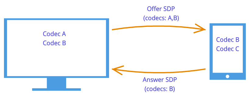
 Figure 7: Codec negotiation
WebRTC technology is trying to confuse us with its new methodology. When establishing a connection, the address of the node to which you want to connect is not specified. Installed first logical connection, not physical, although the opposite was always done. But this will not seem strange if we do not forget that we are using a third-party signaling mechanism.
So, the connection has already been established (logical connection), but there is still no path along which the network nodes can transmit data. It's not all that simple, but let's start simple. Let the nodes be on the same private network. As we already know, they can easily connect to each other using their internal IP addresses (or perhaps some others, if not TCP/IP is used).
Through some callback 'and WebRTC informs us of Ice candidate objects. They also come in text form and, like session descriptors, they simply need to be sent through a signaling mechanism. If the session descriptor contained information about our settings at the camera and microphone level, then the candidates contain information about our location on the network. Pass them on to another node, and it will be able to physically connect to us, and since it already has a session descriptor, it will logically be able to connect and the data will “flow.” If he remembers to send us his candidate object, that is, information about where he himself is on the network, then we will be able to connect with him. Let us note here one more difference from the classic client-server interaction. Communication with the HTTP server occurs according to the request-response scheme, the client sends data to the server, which processes it and sends it via the address specified in the request packet. In WebRTC you need to know two addresses and connect them on both sides.
The difference from session descriptors is that only remote candidates need to be installed. Editing here is prohibited and cannot bring any benefit. In some WebRTC implementations, candidates need to be installed only after session descriptors have been set.
Why was there only one session descriptor, but there could be many candidates? Because the location on the network can be determined not only by its internal IP address, but also by the external address of the router, and not necessarily just one, as well as the addresses of TURN servers. The rest of the paragraph will be devoted to a detailed discussion of the candidates and how to connect nodes from different private networks.
So, two nodes are on the same network (Figure 8). How to identify them? Using IP addresses. No other way. True, you can still use different transports (TCP and UDP) and different ports. This is the information that is contained in the candidate object - IP, PORT, TRANSPORT and some others. Let, for example, use UDP transport and port 531.
Figure 8: Two nodes are on the same network
Then, if we are in node p1, then WebRTC will give us such a candidate object - . This is not an exact format, just a diagram. If we are at node p2, then the candidate is . Through the signaling mechanism, p1 will receive p2's candidate (that is, the location of node p2, namely its IP and PORT). Then p1 can connect to p2 directly. More correctly, p1 will send data to 10.50.150.3:531 in the hope that it will reach p2. It doesn't matter whether this address belongs to node p2 or some intermediary. The only important thing is that data will be sent through this address and can reach p2.
As long as nodes are on the same network, everything is simple and easy - each node has only one candidate object (always meaning its own, that is, its location in the network). But there will be many more candidates when the nodes are in different networks.
Let's move on to a more complex case. One node will be located behind the router (more precisely, behind NAT), and the second node will be located on the same network with this router (for example, on the Internet) (Figure 9).
Figure 9: One node is behind NAT, the other is not
This case has a particular solution to the problem, which we will now consider. A home router usually contains a NAT table. This is a special mechanism designed to allow nodes inside the router’s private network to access, for example, websites.
Let's assume that the web server is connected to the Internet directly, that is, it has a public IP * address. Let this be node p2. Node p1 (web client) sends a request to the address 10.50.200.10. First, the data goes to router r1, or rather to its interior interface 192.168.0.1. After which, the router remembers the source address (address p1) and enters it into a special NAT table, then changes the source address to its own (p1 → r1). Further, in my own way external interface, the router sends data directly to the p2 web server. The web server processes the data, generates a response and sends it back. Sends r1 to the router, since it is in the return address (the router replaced the address with its own). The router receives the data, looks at the NAT table and forwards the data to node p1. The router acts as an intermediary here.
What if several nodes from the internal network simultaneously access the external network? How will the router understand who to send the response back to? This problem is solved using ports. When a router replaces the host address with its own, it also replaces the port. If two nodes access the Internet, then the router replaces their source ports with different. Then, when the packet from the web server comes back to the router, the router will understand by the port who the packet is assigned to. Example below.
Let's return to WebRTC technology, or more precisely, to the part of it that uses the ICE protocol (hence the Ice candidates). Node p2 has one candidate (its location in the network is 10.50.200.10), and node p1, which is located behind the router with NAT, will have two candidates - local (192.168.0.200) and router candidate (10.50.200.5). The first one is not useful, but it is generated nonetheless, since WebRTC does not yet know anything about the remote node - it may or may not be on the same network. The second candidate will come in handy, and as we already know, the port (to get through NAT) will play an important role.
An entry in the NAT table is generated only when data leaves the internal network. Therefore, node p1 must transmit the data first and only after that the data from node p2 can reach node p1.
On practice both nodes will be behind NAT. To create an entry in each router's NAT table, the hosts must send something to the remote host, but this time neither the former can reach the latter nor vice versa. This is due to the fact that nodes do not know their external IP addresses, and sending data to internal addresses is pointless.
However, if the external addresses are known, the connection will be easily established. If the first node sends data to the router of the second node, the router will ignore it, since its NAT table is still empty. However, in the router of the first node, a necessary entry appeared in the NAT table. If now the second node sends data to the router of the first node, then the router will successfully transfer it to the first node. Now the NAT table of the second router also has the necessary data.
The problem is that in order to find out your external IP address, you need a node located on the public network. To solve this problem, additional servers are used that are directly connected to the Internet. With their help, treasured entries are also created in the NAT table.
STUN and TURN serversWhen initializing WebRTC, you need to specify the available STUN and TURN servers, which we will henceforth call ICE servers. If servers are not specified, then only nodes on the same network (connected to it without NAT) will be able to connect. It is immediately worth noting that for 3g networks the use of TURN servers is mandatory.
STUN server is simply a server on the Internet that returns a return address, that is, the address of the sender’s node. The host behind the router contacts the STUN server to traverse NAT. The packet that came to the STUN server contains the source address - the router address, that is, the external address of our node. This is the address STUN the server sends back. Thus, the node receives its external IP address and the port through which it is accessible from the network. Next, WebRTC uses this address to create an additional candidate (external router address and port). Now there is an entry in the router’s NAT table that allows packets sent to the router on the required port to reach our node.
Let's look at this process with an example.
Example (STUN server operation)The STUN server will be denoted by s1. The router, as before, is through r1, and the node is through p1. You will also need to monitor the NAT table - we’ll denote it as r1_nat. Moreover, this table usually contains many records from different nodes of the subnet - they will not be given.
So, at the beginning we have an empty table r1_nat.
Table 2: Packet Header
Node p1 sends this packet to router r1 (it doesn’t matter how, different technologies can be used in different subnets). The router needs to replace the source address Src IP, since the address specified in the packet is obviously not suitable for an external subnet; moreover, addresses from such a range are reserved, and not a single address on the Internet has such an address. The router makes a substitution in the packet and creates a new entry in its r1_nat table. To do this, he needs to come up with a port number. Let us recall that since several nodes within a subnet can access the external network, additional information must be stored in the NAT table so that the router can determine which of these several nodes is destined for the return packet from the server. Let the router come up with port 888.
Changed package header:
Table 4: The NAT table has been updated with a new entry
Here the IP address and port for the subnet are exactly the same as the original packet. In fact, when postbacking, we must have a way to completely restore them. The IP address for the external network is the address of the router, and the port has changed to the one invented by the router.
The real port on which node p1 accepts the connection is, of course, 35777, but the server sends data to fictitious port 888, which will be changed by the router to the real 35777.
So, the router replaced the source address and port in the packet header and added an entry to the NAT table. Now the packet is sent over the network to the server, that is, node s1. At the input, s1 has the following packet:
| 10.50.200.5 | 888 | 12.62.100.200 | 6000 |
Table 5: STUN server received packet
In total, the STUN server knows that it received a packet from the address 10.50.200.5:888. Now the server sends this address back. It's worth stopping here and taking another look at what we just looked at. The tables above are a snippet from header package, not at all from it content. We did not talk about the content, since it is not so important - it is somehow described in the STUN protocol. Now we will consider, in addition to the title, the content. It will be simple and contain the router address - 10.50.200.5:888, although we took it from header package. This is not done often; protocols usually do not care about information about node addresses; it is only important that the packets are delivered to their intended destination. Here we are looking at a protocol that establishes a path between two nodes.
So now we have a second packet that goes in the opposite direction:
Table 7: STUN server sends a packet with this content
Next, the packet travels across the network until it reaches the external interface of router r1. The router understands that the packet is not intended for it. How does he understand this? This can only be determined by the port. He does not use port 888 for his personal purposes, but uses it for the NAT mechanism. Therefore, the router looks at this table. Looks at the External PORT column and looks for a line that matches the Dest PORT from the incoming packet, that is, 888.
| 192.168.0.200 | 35777 | 10.50.200.5 | 888 |
Table 8: NAT Table
We're lucky, such a line exists. If we were unlucky, the packet would simply be discarded. Now you need to understand which node on the subnet should send this packet. No need to rush, let's again remember the importance of ports in this mechanism. At the same time, two nodes on the subnet could send requests to the external network. Then, if the router came up with port 888 for the first node, then for the second it would come up with port 889. Let's assume that this happened, that is, the r1_nat table looks like this:
Table 10: The router replaces the receiver address
| 12.62.100.200 | 6000 | 192.168.0.200 | 35777 |
Table 11: The router changed the receiver address
The packet successfully arrives at node p1 and, by looking at the contents of the packet, the node learns about its external IP address, that is, the address of the router on the external network. He also knows the port that the router passes through NAT.
What's next? What's the use of all this? A benefit is an entry in the r1_nat table. If now anyone sends a packet with port 888 to router r1, then the router will forward this packet to node p1. This created a small narrow passage to the hidden node p1.
From the example above you can get some idea of how NAT works and the essence of a STUN server. In general, the ICE mechanism and STUN/TURN servers are precisely aimed at overcoming NAT restrictions.
Between the node and the server there can be not one router, but several. In this case, the node will receive the address of the router that is the first to access the same network as the server. In other words, we will get the address of the router connected to the STUN server. For p2p communication, this is exactly what we need, if we do not forget the fact that each router will add the line we need to the NAT table. Therefore, the way back will be just as smooth again.
TURN server is an improved STUN server. From here you should immediately take away that any TURN server can also work as a STUN server. However, there are also advantages. If p2p communication is impossible (as, for example, in 3g networks), then the server switches to relay mode, that is, it works as an intermediary. Of course, we are not talking about any p2p then, but outside the ICE mechanism, nodes think that they are communicating directly.
In what cases is a TURN server necessary? Why is there not enough STUN server? The fact is that there are several types of NAT. They replace the IP address and port in the same way, but some of them have additional protection against “falsification” built into them. For example, in symmetrical The NAT table stores 2 more parameters - IP and port of the remote node. A packet from the external network passes through NAT to the internal network only if the source address and port match those recorded in the table. Therefore, the trick with the STUN server fails - the NAT table stores the address and port of the STUN server and, when the router receives a packet from the WebRTC interlocutor, it discards it because it is “falsified”. It did not come from the STUN server.
Thus, a TURN server is needed in the case when both interlocutors are behind symmetrical NAT (each to his own).
Brief summaryHere are some statements about WebRTC entities that you should always keep in mind. They are described in detail above. If any of the statements do not seem completely clear to you, re-read the relevant paragraphs.
- Media stream
- Video and audio data are packaged into media streams
- Media streams synchronize the media tracks that make up
- Different media streams are not synchronized with each other
- Media streams can be local and remote, the local one is usually connected to a camera and microphone, the remote ones receive data from the network in encrypted form
- There are two types of media tracks - for video and for audio.
- Media tracks have the ability to turn on/off
- Media tracks consist of media channels
- Media tracks synchronize the media channels that make up
- Media streams and media tracks have labels by which they can be distinguished
- Session handle
- The session descriptor is used to logically connect two network nodes
- The session descriptor stores information about available methods for encoding video and audio data
- WebRTC uses an external signaling mechanism - the task of forwarding session descriptors (sdp) falls on the application
- The logical connection mechanism consists of two stages - offer (offer) and response (answer)
- Generation of a session descriptor is impossible without using a local media stream in the case of an offer and is impossible without using a remote session descriptor in the case of an answer.
- The resulting descriptor must be given to the WebRTC implementation, and it does not matter whether this descriptor is received remotely or locally from the same WebRTC implementation
- It is possible to slightly edit the session descriptor
- Candidates
- Ice candidate is the address of a node in the network
- The node address can be your own, or it can be the address of a router or TURN server
- There are always many candidates
- The candidate consists of an IP address, port and transport type (TCP or UDP)
- Candidates are used to establish a physical connection between two nodes in a network
- Candidates also need to be sent through a signaling mechanism
- Candidates also need to be passed to WebRTC implementations, but only remote ones
- In some WebRTC implementations, candidates can only be transmitted after a session descriptor has been set
- STUN/TURN/ICE/NAT
- NAT is a mechanism for providing access to an external network
- Home routers support a special NAT table
- The router replaces the addresses in the packets - the source address with its own, if the packet goes to an external network, and the receiver address with the host address on the internal network, if the packet came from an external network
- To provide multi-channel access to an external network, NAT uses ports
- ICE - NAT Traversal Engine
- STUN and TURN servers – assistant servers for NAT traversal
- STUN server allows you to create the necessary entries in the NAT table, and also returns the external address of the host
- The TURN server generalizes the STUN mechanism and makes it always work
- In the worst cases, the TURN server is used as an intermediary (relay), that is, p2p turns into a client-server-client connection.
WebRTC is an API provided by the browser and allows you to organize a P2P connection and transfer data directly between browsers. There are quite a few tutorials on the Internet on how to write your own video chat using WebRTC. For example, here is an article on Habré. However, they are all limited to connecting two clients. In this article I will try to talk about how to organize connection and exchange of messages between three or more users using WebRTC.
The RTCPeerConnection interface is a peer-to-peer connection between two browsers. To connect three or more users, we will have to organize a mesh network (a network in which each node is connected to all other nodes).
We will use the following scheme:
As you know, although WebRTC provides the possibility of P2P connection between browsers, its operation still requires additional transport for exchanging service messages. In this example, the transport used is a WebSocket server written in Node.JS using socket.io:
Var socket_io = require("socket.io"); module.exports = function (server) ( var users = (); var io = socket_io(server); io.on("connection", function(socket) ( // Want a new user to join the room socket.on("room ", function(message) ( var json = JSON.parse(message); // Add the socket to the list of users users = socket; if (socket.room !== undefined) ( // If the socket is already in some room , exit it socket.leave(socket.room); ) // Enter the requested room socket.room = json.room; socket.join(socket.room); socket.user_id = json.id; // Send to other clients in this room a message about the joining of a new participant socket.broadcast.to(socket.room).emit("new", json.id); )); // Message related to WebRTC (SDP offer, SDP answer or ICE candidate) socket.on("webrtc", function(message) ( var json = JSON.parse(message); if (json.to !== undefined && users !== undefined) ( // If the message specifies a recipient and that recipient known to the server, we send the message only to it... users.emit("webrtc", message); ) else ( // ...otherwise we consider the message to be broadcast socket.broadcast.to(socket.room).emit("webrtc", message); ) )); // Someone has disconnected socket.on("disconnect", function() ( // When a client disconnects, notify others about it socket.broadcast.to(socket.room).emit("leave", socket.user_id); delete users; )); )); );
1.index.htmlThe source code for the page itself is quite simple. I deliberately did not pay attention to layout and other beauties, since this article is not about that. If someone wants to make it beautiful, it won’t be difficult.
WebRTC Chat Demo Connected to 0 peers
Send
We still have to use browser prefixes to access WebRTC interfaces.
Var PeerConnection = window.mozRTCPeerConnection || window.webkitRTCPeerConnection; var SessionDescription = window.mozRTCSessionDescription || window.RTCSessionDescription; var IceCandidate = window.mozRTCIceCandidate || window.RTCIceCandidate;
2.1. Determining the room IDHere we need a function to generate a unique room and user identifier. We will use UUID for these purposes.
Function uuid() ( var s4 = function() ( return Math.floor(Math.random() * 0x10000).toString(16); ); return s4() + s4() + "-" + s4() + "-" + s4() + "-" + s4() + "-" + s4() + s4() + s4(); )
Now let's try to extract the room identifier from the address. If one is not specified, we will generate a new one. Let's display a link to the current room on the page, and, at the same time, generate the identifier of the current user.
Var ROOM = location.hash.substr(1); if (!ROOM) ( ROOM = uuid(); ) room_link.innerHTML = "Link to the room"; var ME = uuid();
2.2. WebSocketImmediately when opening the page, we will connect to our signaling server, send a request to enter the room and specify message handlers.
// Specify that when closing a message, you need to send a notification to the server about this var socket = io.connect("", ("sync disconnect on unload": true)); socket.on("webrtc", socketReceived); socket.on("new", socketNewPeer); // Immediately send a request to enter the room socket.emit("room", JSON.stringify((id: ME, room: ROOM))); // Helper function for sending address messages related to WebRTC function sendViaSocket(type, message, to) ( socket.emit("webrtc", JSON.stringify((id: ME, to: to, type: type, data: message ))); )
2.3. PeerConnection settingsMost ISPs provide Internet connections via NAT. Because of this, direct connection becomes not such a trivial matter. When creating a connection, we need to specify a list of STUN and TURN servers that the browser will try to use to bypass NAT. We will also indicate a couple of additional options for connection.
Var server = ( iceServers: [ (url: "stun:23.21.150.121"), (url: "stun:stun.l.google.com:19302"), (url: "turn:numb.viagenie.ca", credential: "your password goes here", username: " [email protected]") ] ); var options = ( optional: [ (DtlsSrtpKeyAgreement: true), // required for connection between Chrome and Firefox (RtpDataChannels: true) // required in Firefox to use the DataChannels API ] )
2.4. Connecting a new userWhen a new peer is added to the room, the server sends us a new message. According to the message handlers above, the socketNewPeer function will be called.
Var peers = (); function socketNewPeer(data) ( peers = (candidateCache: ); // Create a new connection var pc = new PeerConnection(server, options); // Initialize it initConnection(pc, data, "offer"); // Save peers in the list peers peers.connection = pc; // Create a DataChannel through which messages will be exchanged var channel = pc.createDataChannel("mychannel", ()); channel.owner = data; peers.channel = channel; // Install event handlers channel bindEvents(channel); // Create an SDP offer pc.createOffer(function(offer) ( pc.setLocalDescription(offer); )); ) function initConnection(pc, id, sdpType) ( pc.onicecandidate = function (event) ( if (event.candidate) ( // When a new ICE candidate is detected, add it to the list for further sending peers.candidateCache.push(event.candidate); ) else ( // When candidate discovery is complete, the handler will be called again, but without candidate // In this case, we first send the peer an SDP offer or SDP answer (depending on the function parameter)... sendViaSocket(sdpType, pc.localDescription, id); // ...and then all previously found ICE candidates for (var i = 0; i< peers.candidateCache.length; i++) { sendViaSocket("candidate", peers.candidateCache[i], id); } } } pc.oniceconnectionstatechange = function (event) { if (pc.iceConnectionState == "disconnected") { connection_num.innerText = parseInt(connection_num.innerText) - 1; delete peers; } } } function bindEvents (channel) { channel.onopen = function () { connection_num.innerText = parseInt(connection_num.innerText) + 1; }; channel.onmessage = function (e) { chatlog.innerHTML += "Peer says: " + e.data + ""; }; }
2.5. SDP offer, SDP answer, ICE candidateWhen we receive one of these messages, we call the handler for the corresponding message.
Function socketReceived(data) ( var json = JSON.parse(data); switch (json.type) ( case "candidate": remoteCandidateReceived(json.id, json.data); break; case "offer": remoteOfferReceived(json. id, json.data); break; case "answer": remoteAnswerReceived(json.id, json.data); break; ) )
2.5.0 SDP offer function remoteOfferReceived(id, data) ( createConnection(id); var pc = peers.connection; pc.setRemoteDescription(new SessionDescription(data)); pc.createAnswer(function(answer) ( pc.setLocalDescription(answer ); )); ) function createConnection(id) ( if (peers === undefined) ( peers = (candidateCache: ); var pc = new PeerConnection(server, options); initConnection(pc, id, "answer"); peers.connection = pc; pc.ondatachannel = function(e) ( peers.channel = e.channel; peers.channel.owner = id; bindEvents(peers.channel); ) ) ) 2.5.1 SDP answer function remoteAnswerReceived(id , data) ( var pc = peers.connection; pc.setRemoteDescription(new SessionDescription(data)); ) 2.5.2 ICE candidate function remoteCandidateReceived(id, data) ( createConnection(id); var pc = peers.connection; pc. addIceCandidate(new IceCandidate(data)); ) 2.6. Sending a messageWhen the Send button is clicked, the sendMessage function is called. All it does is go through the list of peers and try to send the specified message to everyone.