DIY external wifi antenna. Types of WiFi antennas
Good afternoon, dear readers of the blog site. Quite recently, I talked about the possibility of increasing the coverage area by installing . However, not everyone likes this situation, and many simply do not want to give extra money. That is why I decided to describe what reinforced wifi antenna for a router with your own hands.
The need to increase the coverage area or achieve a more stable signal comes precisely at the moment when the user simply cannot connect to a remote part of his apartment or via wireless network several times. Most affordable way decide this problem postpone wireless router closer to the receiver, but we are not looking for easy ways and will do enhanced wifi do-it-yourself antenna for a router.
Unfortunately, this method Only suitable for models with external antennas.
In my arsenal there are several ways to make an improved antenna for wifi router, but since my article is aimed at inexperienced users, then I will try to talk in detail about three options for homemade Wi-Fi amplifiers.
Amplified wifi antenna from a CD box
No matter how ridiculous it may sound, this option of making an antenna for a router with your own hands really gives quite good result. For production we will need:
- Box for discs for 25 pieces
- Unnecessary CD
- Copper wire, 30 centimeters, cross-section 2 sq/mm (more is possible, but do not overdo it with thickness)
- Coaxial cable for connection
- Tools (soldering iron, pliers, glue and file)
- Additional SMA connector
Open the box and cut off the guide at a distance of about 20 mm
Then, using a file, we make indentations in the form of a cross, for the subsequent installation of a diamond.
Thanks to pliers from pre-prepared copper wire create a double rhombus. The length of each side of a separate rhombus should not exceed three centimeters. The resulting product can be seen in the figure below.
The ends of the wire should meet in the middle.
At the junction of the ends, we solder the wires and the ends themselves, respectively.
The next step is to insert coaxial cable through the hole in the guide in the box and using adhesive, fix the resulting diamond in the grooves of the guide.
For better fixation, I advise you to fix all freely movable parts with glue.
Cover the resulting structure with a lid. amplified antenna wireless router and using the SMA connector we connect it to the router itself.

This completes our wifi antenna for the router. When I personally decided to test the result, I was very pleasantly surprised by the signal strength in remote rooms.
The disc box can always be replaced with sheet metal, and instead of a plastic guide, use a soldered metal tube. There are a lot of opportunities for improvement.
DIY amplified antenna for a router from a tin can
From the name you can already understand that this method is primitive to the point of disgrace and there is no need to spend money on purchasing additional materials.
In the store, you just need to buy a can of soda (or beer) and after it is empty, you can start making a homemade wifi amplifier for your router.
First, you should rinse and dry it to get rid of any remaining contents. Then, using scissors, we pierce the can at the bottom, next to the bend that turns into the bottom, and cut it off. Then we make a cut along the entire length until the bend turns into top part. Then we cut off the cover along the circumference on both sides of the longitudinal section almost to the very end, but at the same time leaving a small area for the stability of our screen. It will be clearer if you look at the figure below.

To make our design more rigid, we can not cut off the bottom of the jar, but do the same as we did with the lid, which will not allow the screen to bend arbitrarily.
The next step is to mount the antenna. We place our structure on the antenna, and for better fixation we take plasticine, which will not allow all this stuff to move in space.
If your router has not one, but two transmitters, then such an amplifier needs to be made for each, which will allow you to send a more powerful signal in several directions at the same time.
At first glance, such a device looks very elementary and unreliable, but the amplification effect makes it clear that even a simple design can produce excellent results.
Unfortunately, the two methods given above are intended for directional signal improvements. This scheme is suitable for those users who have installed a wireless router in the corner of the room and there is no need to “distribute wifi” to neighbors.
Homemade reinforcing attachment for the router
Another fairly simple way to strengthen the Wi-Fi signal with your own hands is to use the so-called attachment. The manufacturing principle is incredibly simple. You should have on hand a wire with a cross section of 1.5 - 2.5 mm, a piece of cardboard, pliers and scissors.
First of all, we cut several pieces of wire of different lengths (starting with the shorter one and gradually increasing by 4 mm). The number of such pieces will depend on what kind of wifi antenna you want to get.
We cut a piece of cardboard of such length and width that it will not bend under the weight of the wire. Next, we attach the wire to the cardboard by piercing it in equal sections.
Using scissors, cut a hole for mounting. The appearance of the resulting structure is very similar to .

Naturally, if your router has several transmitters, then we make such an attachment for each of them.
This design will really help increase the coverage area and enhance signal transmission.
All the described methods for making an antenna for a router with your own hands are quite simple and do not require additional skills. However, if during the work any questions arise or there is a proposal to supplement this article, then do not hesitate to leave them in the comments.
To better consolidate the material you have read, I suggest watching the corresponding video.
Recently a 3G antenna was shown on the site. I would like to present three Wi-Fi antennas not just copied from other sites, but made by myself and tested in real conditions. I needed Internet access in a house next door to my router, at a distance of 150-200 m.
The first antenna http://usd.ucoz.ru/publ/2-1-0-71 is omnidirectional, made from a piece of RG-213 cable. I’ll say right away that this antenna can only be used as a regular whip antenna, and the characteristics declared on one of the sites did not live up to their expectations. The range of this antenna was 30 meters. Therefore, I no longer experimented with it.
Cleaned the cable. The length of the central core is 28 mm.
For structural rigidity, I placed a ring made of copper wire with a cross-section of 2.5 mm² on the internal dielectric.


The length of the counterweight arm was 31 mm, and the diameter of the lower ring was 54 mm.

Second spiral WiFi antenna HELIX made from a piece of plastic sewer pipe with a diameter of 40 mm and a piece of electrical wire with a cross-section of 2.5 mm². http://www.wifiantenna.org.ua/antennas/helix/

I wound 12 turns of wire onto the pipe with a turn pitch of 33 mm and glued it with Moment glue, this will give a very strong winding around the pipe.

To connect the antenna to the reflector, I used a bottle from soap bubbles. I screwed it to the reflector with a screw, and attached the antenna with glue.

Since the RF output of all access points and routers typically has an impedance of 50 ohms, the cable must be wave impedance m 50 ohm. To match the antenna with the cable, I soldered a rectangular triangle made of tin to the end of the wire with dimensions of 71*17 mm along the legs.


To connect the antenna to the cable, I drilled a hole in the reflector and soldered copper tube.


Soldered to the compensator triangle,

And the screen was bonded and soldered.


The cable used RG-58/U with a characteristic impedance of 50 ohms. I soldered an RP-SMA(m) connector to the other end of the cable.
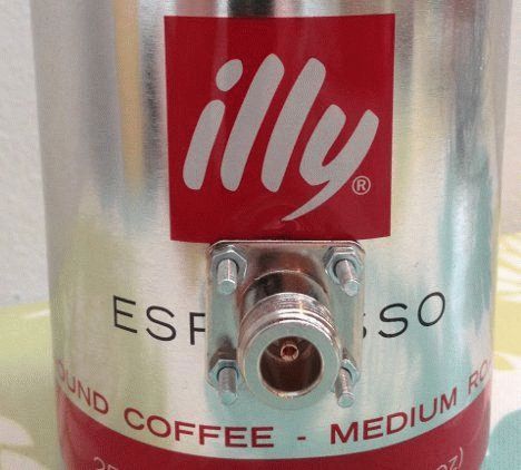
Third antenna from a can
After reading a single article about making antennas from a can, I decided to take a 1-liter can of Zhigulevsky beer.
It has a smooth flat bottom and a suitable diameter.
Http://www.cqham.ru/cantenna.htm - on the link there is a calculator for calculating the antenna based on the diameter of the can and the estimated frequency of the antenna. 
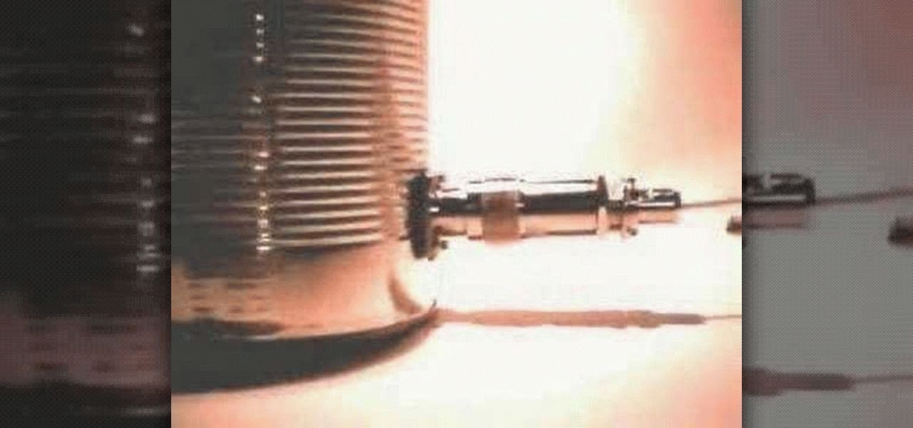
To install the cable and attach the antenna itself, I used an F-connector. 
The central contact of the connector was drilled out. 
I screwed the connector to the mast. 
I stripped the central core of the cable to the required length. 
I drilled a hole in the jar. 
Assembled the antenna


And painted it with nitro enamel from a spray can.

Now about testing antennas in real conditions.
I already wrote about the first antenna. Its radius was about 20-30 meters.
Communication check took place between D-Link router DIR-300 and tablet computer for access to Internet pages
and video communication via Skype from two points. 
The first point was at a distance of 240 m from the antenna,
At a distance of 450 m, access to the Internet was at a speed of 1 Mb/s, but the video connection via Skype was constantly interrupted.
The can antenna performed better than the helical antenna.
At a distance of 450 m, video communication via Skype was satisfactory. I came to the following conclusion: an antenna from a can has a narrower radiation pattern and is good for creating a connection with remote users.
But to do this, it needs to be “targeted” at that same user. U helical antenna The diagram is wider, so the connection is possible without careful “aiming”.
As for the distance, I connected to the Internet via Tablet PC, and they have built-in Wi-Fi antennas with low gain, therefore the distance is short.
Those. I get a good signal from the router, but when I connect I can’t get an IP address and the connection breaks down. I basically achieved the desired results. 450 m is more than enough for me.
But for those who need longer distance for communication, my suggestions will be as follows: put the same external antennas on both sides,
both from the router or access point and from the network adapter, and install a more powerful access point such as SENAO ECB-8610S or EnGenius ECB-3500.
They have six times the output power of conventional routers, but the price is five to six times more expensive.
Settings Wi-Fi networks demonstrates quite a lot of nuances. I came across someone trying to share the Internet with home users. One computer is connected to the provider via cable. An access point mode is created, a security protocol and a password are selected. Home users use the Internet in parallel. The technique does not work, thanks to the provider using a private line. The exit is located. Obstacles standing between people and high-speed Internet, are powerless to prevent a homemade Wi-Fi antenna from improving signal reception and transmission, communication range and speed naturally increase.
Purpose of homemade Wi-Fi antennas
Antennas adorn many devices. Let's list:
- Tablet.
- IPhone.
- Laptops.
- Wi-Fi modems.
- Wi-Fi routers, access points.
- Cell towers.
Homemade antenna for Wi-Fi adapter will expand the capabilities of electronics. The access point is distinguished by its ability to transmit the signal omnidirectionally. The power spreads, filling the azimuths. By supplementing the access point with a special external purchased, homemade antenna, it can impart directional properties to the radiation. Will increase the range of reliable reception in the selected azimuth.
Stop breaking your smartphones by connecting an external antenna and assemble it yourself for an access point. Most antennas sold in stores have a circular radiation pattern, radiating equally, omnidirectionally, dividing the power in azimuths.
Powerful homemade Wi-Fi antennas have a much smaller field of view and, in some cases, will provide more confident reception. Reflector-equipped devices have a radiation pattern with one central lobe. Remove the reflector and you get a figure eight. There will be a dead zone in the plane of the emitter; there will be no signal. Take from direction homemade antenna for a Wi-Fi router is not possible. The access point installation scheme is as follows:
- The device is connected to a computer (electrical network).
- The channel is selected.
- The setting is carried out at full power.
- The protocol type is selected.
- The password and network name are set.
People walk around happy with the new accessible point. Let's take a closer look at the process; let's take a moment to grab a soldering iron and pliers. Like a transmitter, a radio-electronic device, an antenna, or a router have a certain peak of capabilities in the middle of the range. For example, on 2.4 GHz there are often 14 channels. The power of the transmitted signal is higher in the middle, for example, the sixth channel. Although each line occupies 22 MHz of the spectrum, the measurement is carried out at a field level of 0.707 (√2/2) maximum on both sides of the carrier frequency.
For reference. Determined by the modulation type, sometimes only the pilot signal remains, one band. Rectangular pulses, computer signals are just like that, have a pronounced maximum, a bunch of side lobes. As a result, the spectrum width real signal equal to infinity. The cyclic voltage band is limited, to which the process emitted by the Wi-Fi protocol does not come close.
A homemade omnidirectional Wi-Fi antenna does not the best option. Nothing will change. Homemade directional antenna Wifi is better, we will make it from wire, foil PCB, copper tube. They are so sensitive. Transmitted and received powers are concentrated in a narrow sector. It will improve the quality of transmission by carefully positioning users and the access point. You can judge how important the arrangement is by one curious case:
- The office called a technician. They said: between 12.00 and 14.00 the access point collapses. The technician took out a special device for estimating occupied frequencies and began the study. Similar programs provided by Android smartphone OS. Use by selecting a channel before installation. Conduct research throughout the day for several days in a row, avoiding incidents. We bring to light what the master discovered: the neighboring office, separated by a wall, painted lunch. The workers took turns using the microwave (using the 2.4 GHz frequency). Poor insulation household appliances, the lack of grounding allowed the radiation to exhibit narrow-band interference at the frequency of the magnetron. The solution to the problem turned out to be simple: the access point was moved to the opposite end of the office.
If you had a simple homemade Wi-Fi antenna from a beer can with a reflector on hand, the heroes might not know what’s next door powerful source harmful radiation. The reflector gives the access point directionality and will dampen the radiation coming from behind the wall. Another advantage of directional antennas, which we will make with our own hands today. By the way, when buying a microwave, try to determine safety. You need to plug the device into a grounded outlet and place it in the work compartment. cellular telephone, close the door, dial the number. The signal passes - it will come out harmful radiation magnetron. Avoid sitting nearby. Let's discuss how to make a homemade Wi-Fi antenna.
DIY directional Wi-Fi antenna
Tools you will need:
- Soldering iron (solder, rosin, stand).
- Pliers.
- Small flathead screwdriver.
- Vernier caliper, ruler.
- Drill with a drill for a copper pipe.
Materials you will need:
- A piece of foil double-sided PCB as a reflector.
- Copper wire with a diameter of 1.2 mm and a length of 30 cm (only 26 cm of which will be needed).
- The RK-50 cable is not too long so as not to dampen the signal.
- A piece of copper tube 10 cm long for the RK-50 cable to pass inside.
Let's start with a copper tube. We saw through one end by 1.5 mm, removing two-thirds of the wall. The antenna will be soldered to the remaining piece. We create a bi-square contour with a side of 30.5 mm from wire. The size was selected based on the 2.4 GHz band setting condition.
In a similar way, you can make any antenna with a horizontal or vertical polarization signal. Including television. A homemade Wi-Fi antenna is suitable for a tablet, phone, or modem. If you know where to connect.
Please note that the side of the squares is given according to the middle section of the wire. Between the nearest edges there will be 30.5 - 1.2 = 29.3 mm. You can use it. We begin to bend, finding the middle. We use the edge of the ruler as a support and determine the state when the cut begins to balance. We make a bend of 90 degrees, this will be the point where the central core of the RK-50 will connect. We bend the wire, getting a “square eight”, both ends should return strictly symmetrically. We cut it a couple of millimeters short of the initial bend. We tin the ends and put the figure eight aside.
We mark the middle of the PCB and drill a hole so that the copper tube can barely fit in. We cheat both sides. We take a copper tube and tin the outer edge of the thin wall left by the first stage. The figure eight is 1.5 cm away from the reflector. We tin the tube in a circle, with the rim at the specified distance from the edge (without taking into account the thin wall). Solder the tube to the board, preferably at an angle of 90 degrees. We place both ends of the figure eight on a thin wall so that the initial bend does not touch the tube. Orienting the figure eights parallel larger side textolite at a distance of 1.5 cm. Now the reflector is grounded.
The RK-50 cable is pulled inside, the screen is placed on the copper tube, the core is placed on the initial bend of the figure eight. We mount the connector on the opposite end, simply solder the cut to necessary contacts modem, telephone, any other device. Let's start the test. The figure eight must be mounted vertically for horizontal polarization. If it works, we find silicone sealant that is not afraid of frost and precipitation, and fill the place where the cable exits with the antenna with a good layer. After hardening, the antenna will successfully withstand rain.
If you replace the wire with a thick conductor PV1 of a sufficiently large cross-section (2.5 mm 2), we will strip the braid at the point of initial bending and at the ends. A homemade Wi-Fi antenna for a laptop will be protected against bad weather. Today, heat-shrinkable materials are produced. The heated film tightly wraps the product, protecting it from the vagaries of bad weather.
Outside the home, the signal strength is always low. In a cafe or business center, routers are not installed in every room. And the power of the receivers is modern laptops and smartphones is quite small.
Antenna for reception WiFi signal you can do it yourself
You can pay attention to popular solutions - expensive external antennas. Someone uses a 3G modem with a router function, but the Internet speed is thus reduced and the cost increases significantly. We will tell you how to make an antenna for Wi-Fi from available means.
The financial cost of a Wi-Fi antenna should not be more than $35. You will need:
- USB receiver for Wi-Fi networks in dongle form factor. You can find one in large stores electronics or radio markets.
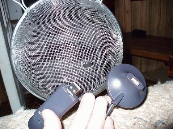
- Any kitchen utensils of a hemispherical shape (made of metal). A colander or sieve will do.
- Passive extender USB type A. If finances allow, then an active one is still better - it will allow you to place the antenna higher. We can connect 2-3 cables when there is no extension cord of the required size.
- Consumables: hot glue, tape, piece of garden hose (required). Foil, rope (optional).
How to choose the right parts?
For our purposes, a Wi-Fi receiver must meet several parameters:

We will need to make the antenna directional. It means that USB cable must be of sufficient length. Calculate it in advance. The cable should not be longer than 5 meters, otherwise signal distortion may occur.

Cookware
The best cookware for these purposes is a pot with a semicircular mesh bottom. Asian dishes, a steamer, a sieve or a lamp cover will do. The hemispherical shape and metal body are the main requirements. If you are planning to make a large antenna, an old television antenna will do just fine. Please note possible problems with installation.

Assembling and connecting the receiver
Connect the Wi-Fi adapter and part of the extension cord to the antenna. To do this, it is better to use hot melt glue or double-sided tape. The adapter should be installed in the center of the antenna, a few centimeters above its surface (ideally). It is important to direct the receiving center of the antenna exactly to the point of signal transmission, since it is highly directional.

Connect the desired end of the USB extension cable to the computer. Install the receiver in the same way as a standard Wi-Fi adapter.
IMPORTANT. It is better to immediately adjust the signal level.
This can be done using programs, for example:
- NetStumbler, Free Wi-Fi Scanner, NetSpot (for Windows);
- NetSpot (for OS X);
- LinSSID, iwScanner (Linux).
We looked at making the most primitive antenna for receiving a Wi-Fi signal. Further more!
Antenna "Bikvadrat"
Another name for Wi-Fi signal receivers of this type is “Kharchenko’s zigzag”. A biquad antenna is relatively easy to make. It refers to optimal options according to the ratio of complexity, production time and result obtained.
Components
For a biquad antenna we will need:
- copper tube or N-connector;
- one-sided textolite;
- copper wiring (diameter 1.5–3 mm);
- cable RG-6U (coaxial).
These components can be found at your local radio market or radio supply store.
Procedure

Helix antenna
Another interesting type of antenna can be used as a signal receiver for the router. This is a spiral design that was invented back in 1947. According to some reports, it is capable of receiving a signal from a distance of about 650 meters.
Components
- A plate made of copper or aluminum - for the reflector. It shouldn't be too thin.
- Copper wiring about 150 cm long and at least 1 mm in diameter.
- Fastenings.
- Round vinyl core.
- Copper foil that will need to be wrapped around the core.
- Connector
Wireless based WiFi technology today it is present everywhere. This is a radio communication standard that provides data transmission at a frequency of 2.4 GHz. It is mainly used to organize an Internet connection between an access point and a subscriber device, but it can also have other applications in industry.
It is most widely used to connect to a wired access point, the so-called. router with the ability to move within range WiFi signal. The quality of the latter’s propagation directly depends on the antenna, built-in or external.
The principle of operation of a WiFi antenna
This device works in the same way as the antennas in conventional radios. The only difference is that in the router the antenna simultaneously transmits and receives signals. Currents are induced in it high frequency, the quality of this process is influenced by the design of the device and the material from which it is made.
Size is of secondary importance, so current antennas for Wi-Fi connection are quite ergonomic and also have an aesthetic design
There are two types of antennas:
- Internal – installed for optimal distribution of Wi-Fi signal inside the building.
- External – used outside buildings to increase coverage area in open areas.
All antenna devices are also divided depending on the direction of the signal into unidirectional and unidirectional. The first ones send pulses only in one direction in the form of a beam and are equipped with a reflector. This design significantly increases the signal power in a given direction while it is absent in the rest, which reduces the risk of unauthorized connection to the network.
Equidirectional antennas are the most common design in consumer electronics. All routers are equipped with them; the signal propagates with equal power in all directions.
Convenient for use in the home or office, but due to the unidirectional action, the coverage area is less than that of unidirectional designs.
When passing through physical obstacles the signal loses some of its power, so reception may be poor at different points in the coverage area various quality. For optimal signal distribution through an unidirectional antenna, the access point should be installed in the center of the room.
Advantages and disadvantages
Modern antennas, including for Wi-Fi standard do not have any disadvantages, which was largely made possible thanks to the use of modern electronic components.
The move away from pin-type telescopic models made of metal, still used today in analog radio reception, has made it possible to significantly reduce dimensions, cost and weight. The main components from which antennas are made are plastic, its derivatives, and polymer materials.
Modern design and miniature size allow you to place it in any setting or even decorate it with interior items. A special connection interface makes the antenna as efficient as possible and minimizes signal loss at the connecting contacts. Big choice models makes it possible to select the product that best suits technical parameters specific coverage area.
Varieties

The main difference, in addition to the installation location and direction of action, is the dimensions, which determine the range and signal amplification factor.
- Pin- can be up to half a meter in height. They create omnidirectional signal propagation and are used to enhance the reception area from an access point located in a building.
- Flat– They are usually a square-shaped plate with a thickness of at least 10 mm and sides of about 300 mm. Designed to transmit a signal to another access point and can cover a distance of several kilometers. Mounted externally on a pole or wall.
- Panel internal– are a desktop device with a directional spectrum of action. A special difference is the flat panel with adjustable angle of inclination relative to the base, which allows you to most accurately direct the beam. Are different small in size and also provides the possibility of wall mounting due to the length of the wire.
Which antenna to choose

All antennas for indoor installation, as a rule, have the same signal amplification rates and differ in design. Therefore, when choosing, the direction of the coverage area, and accordingly its area, is of fundamental importance.
- IN large rooms(offices), located separately - omnidirectional models are used if the coverage radius is sufficient for stable communication throughout the entire room.
- In rooms with a large number of partitions and an entry point, located in the outer room, it is advisable to use unidirectional Wi-Fi transmitters.
- In buildings with a large number of Internet clients If it is necessary to secure the network from hacking, unidirectional models are used.
- At home, an omnidirectional antenna is usually used, however, the location of the insertion point and the thickness of the baffles should be considered. In older buildings with thick brickwork, there may be significant signal attenuation through just one partition. In such cases, it is better to localize the beam using a unidirectional antenna.
What to look for when choosing
The main attention is paid to the signal gain and, of course, the manufacturer's brand. It depends on the coefficient on what area it will be possible to good quality gain access to the network. IN accompanying documents This parameter and the corresponding coverage area are indicated for the device.
The length of the connecting cord also matters, especially if the antenna is placed above the router, which is usually done.
It is advisable that the connecting plug matches the input hole on the router. It should be borne in mind that when using an adapter, some of the signal power will be lost.
Review of the best models
– device for internal use. It is characterized by one-sided action and can be installed on horizontal and vertical surfaces, including being attached to the wall of the system unit using built-in magnets.
The connecting cable is 1 m long, has a resistance of 50 Ohms and is equipped with an SMA connector. The gain is 6 dBi. The radiating element is a metal rectangular plate with sides 28x52mm enclosed inside the emitter housing. The price of the device starts from 1200 rubles.

– antenna for indoor installation with horizontal or vertical mounting. The gain reaches 9 dBi. Connecting cable resistance 50 Ohm, length 1 m. Equipped with an RCA connector. The emitter has a square shape and is located inside a plastic case. The cost of the product is 1600 rubles.

– whip antenna for internal use, omnidirectional action. It is characterized by a high gain - up to 7 dBi, which is significantly higher than that of the standard antennas that come with the router. Mounts to a horizontal surface, wall or system unit PC magnets.
When installed on a wall, it is possible to change the angle of inclination. Equipped with a cable with a resistance of 50 Ohms, 1.5 m long with an SMA connector. Provides direct connection to an access point without cable. The cost of the device will be about 1600 rubles.

– panel antenna for outdoor installation. Provides signal transmission between two access points located at a considerable distance from each other. Capable of providing communication over a distance of up to 8 km at speeds of up to 1 Mb/s. With speeds up to 11 Mb/s at a distance of up to 3 km.
The housing has protective covering from sealant. The gain reaches 18 dBi. The cable is connected via an N type connector; the cable length is selected independently based on the distance to the access point. The cost of the antenna is about 10,500 rubles.

How to make it yourself
You can make such a device yourself; within an apartment it will help strengthen the signal if it is weakened by a large number of partitions. The aluminum beer can design is most popular due to its efficiency and simplicity. You will need:
- Tremple for clothes.
- Two liter aluminum cans.
- Soldering iron, solder.
- Wire 50 Ohm.
- Connection connector.
Instead of a trempel, you can take a metal-plastic flexible pipe. It is used for both external and internal installation, since it has an aesthetic appearance and is not susceptible to exposure to natural factors.
Step-by-step instruction
- Holes are cut in the bottom of the cans after which they must be placed on the lower part of the trempel, having previously cut it, or a pipe must be passed through them.
- The holes in the cans are made of such a size that they fit tightly and did not shift when changing position in space. The pipe must be looped and a hook must be provided for fixing it to the base.
- For cans located on a trempel– it is necessary to remove paint from the cable soldering areas. Then strip the cable, separating the braid and feeder, tin them and solder each to one of the cans. To the other end of the cable, solder a connector corresponding to the one located on the access point.
- For cans on metal-plastic pipes- V in this case both cans are soldered to the feeder wire. You can make a bridge between them from a wire of the same cross-section by soldering the feeder to one of the cans. The antenna screen will be a layer of metal foil laid under the outer coating of the MP pipe. It is necessary to carefully cut and remove protective film and solder the braid to the foil. This place must be insulated and secured with adhesive tape to prevent breakage.
Connection and setup
Before connection, the standard antenna is removed. You should check the settings of the access point to ensure that the maximum signal reception level is set; if this is not the case, then apply individual parameters.