Types of LAN cables. LAN based on balanced twisted pair
Cables used to build infrastructure computer networks, are available in a wide range of varieties. Among the most popular are coaxial, twisted pair, and optical fiber. What are the specifics of each of them? What are the features of installing the most common type - twisted pair?
Cable types: coaxial
Among the historically earliest types of cables used in network connections, - coaxial. Its thickness is approximately the same as that of a computer power supply, designed to work with a 220 V outlet.
The structure of the coaxial structure is as follows: in the very middle there is a metal conductor, it is wrapped in thick, most often plastic, insulation. On top of it is a braid of copper or aluminum. The outer layer is an insulating shell.
The connection of the network cable of the type in question can be done by:
BNC connector;
BNC terminator;
BNC-T connector;
BNC barrel connector.
Let's consider their specifics in more detail.
The BNC connector is supposed to be placed at the ends of the cable and is used to connect to T- or barrel connectors. A BNC terminator is used as an isolating barrier that prevents signal movement along the cable. Correct functioning of the network without this element is in some cases impossible. A coaxial cable requires the use of two terminators, one of which requires grounding. The BNC-T connector is used to connect the PC to the main line. There are three slots in its structure. The first one is connected to the computer connector; the other two are used to connect different ends of the line. Another type of connector for coaxial cable is the BNC barrel. It is used to connect different ends of a highway, or to increase the radius of a computer network.
Among the useful features of coaxial designs is that there are no problems with deciding how to connect two network cables of this type. It is enough to ensure reliable contact of the conductive cores, of course, subject to the technology of pairing the insulation and the screen mesh. However, coaxial cable is quite sensitive to electromagnetic interference. Therefore, in the practice of building computer networks, it is now used quite rarely. However, it is indispensable in terms of organizing the infrastructure for transmitting television signals - from dishes or cable providers.
twisted pair
Probably the most common network cables for computers today are called “twisted pair”. Why this name? The fact is that the structure of this type of cable contains paired conductors. They are made of copper. Standard cable The type in question includes 8 cores (thus, 4 pairs in total), but there are also samples with four conductors. The so-called pinout of a network cable of this type (correlating each core with a particular function) involves the use of insulation of a certain color on each conductor.

The external insulation of the twisted pair is made of PVC, which provides sufficient protection of the conductive elements from electromagnetic interference. There are the types in question - FTP and STP. In the first, the foil performing the corresponding function is located on top of all the cores, in the second - on each of the conductors. There is an unshielded modification of twisted pair - UTP. As a rule, cables with foil are more expensive. But it makes sense to use them only if there is a need for high-quality data transmission over a relatively long distance. For home networks, an unshielded twisted pair version is quite suitable.
There are several classes of the corresponding type of structure, each of them is designated as CAT with a number from 1 to 7. The higher the corresponding indicator, the better the materials that ensure signal transmission. Modern network cables for computers for data exchange via Ethernet in home networks require elements to comply with CAT5 class. In connections that use twisted pair, connectors are used that would be correctly classified as 8P8C, but there is also an unofficial name for them - RJ-45. It can be noted that cables that meet at least the CAT5 and CAT6 classes can transmit data at speeds close to the maximum for the type of structure under consideration - up to 1 Gbit/s.
Optical fiber
Perhaps the most modern and fastest network cables for computers are fiber optic cables. Their structure contains light-conducting glass elements, which are protected by durable plastic insulation. Among key advantages These network cables for a computer have high immunity to interference. Also, data can be transmitted over a distance of about 100 km via optical fiber. The connection of cables of this type to devices can be carried out using various types of connectors. Among the most common are SC, FC, F-3000.
What does this high-tech network cable for a computer look like? Photo of the fiber optic structure below.

The intensity of practical use of optical fiber is limited by the fairly high cost of the equipment necessary to transmit data through it. However, in Lately Many Russian providers actively use this network cable for the Internet. According to IT experts, with the expectation that the corresponding investments will pay off in the future.
Evolution of cable infrastructure
Using the example of the three noted types of cables, we can trace some evolution in the aspect of building computer network infrastructure. Thus, initially, when transmitting data via the Ethernet standard, coaxial structures were used. At the same time, the maximum distance over which a signal could be sent from one device to another did not exceed 500 meters. The maximum over coaxial cable was about 10 Mbit/sec. The use of twisted pair cables has significantly increased the dynamics of file exchange on computer networks - up to 1 Gbit/sec. It is also possible to transfer data to duplex mode(one device could both receive signals and send them). With the advent of optical fiber, the IT industry was able to transfer files at speeds of 30-40 Gbit/sec or more. Thanks largely to this technology, computer networks successfully connect countries and continents.

Of course, when working with a PC, many other types of cables are used that are used in the installation of computer networks. Theoretically, for such purposes, you can use, for example, a USB cable, although this will not be very effective, in particular, due to the fact that within the framework of the standard USB data can be transmitted over a short distance - about 20 m.
How to connect twisted pair
Twisted pair, as we noted above, is today the most common type of cable in the design of computer networks. However, its practical use is characterized by some nuances. In particular, they reflect such an aspect as the pinout of the network cable, which we mentioned above. It is important to know how to correctly position the wires in the area where they come into contact with the RJ-45 connector. The procedure by which a twisted pair is connected to the corresponding element is called crimping, since during its implementation a special tool is used that involves force on the structure.
Nuances of crimping
During this procedure, the connectors are securely fixed to the ends of the twisted pair. The number of contacts in them corresponds to the number of cores - in both cases there are 8 such elements. There are several schemes within which twisted pair cables can be crimped.
Next we will look at the relevant specifics. But first, the person working with the cable needs to properly hold the connectors in their hands. They should be held so that the metal contacts are located on top.

The plastic latch should be directed towards the person doing the crimping. In this case, the 1st contact will be on the left, and the 8th contact will be on the right. Numbering is an extremely important aspect of working with twisted pair cable. So, what crimp schemes are used by network infrastructure specialists?
First, there is a network cable design called EIA/TIA-568A. It assumes the arrangement of the cores in relation to the metal contacts of the connector in the following order:
For 1 contact: white-green;
For the 2nd: green;
For the 3rd: white-orange;
For the 4th: blue;
For the 5th: white and blue;
For the 6th: orange;
For the 7th: white-brown;
For the 8th: brown.

There is another scheme - EIA/TIA-568B. It assumes the arrangement of the cores in the following order:
For 1 contact: white-orange;
For the 2nd: orange;
For the 3rd: white-green;
For the 4th: blue;
For the 5th: white and blue;
For the 6th: green;
For the 7th: white-brown;
For the 8th: brown.

You now know how to connect a network cable to a connector. But it is useful to study the specifics regarding various twisted pair connection schemes to certain devices.
Crimping and connection type
So, when connecting a PC to a router or switch, you should use the direct connection method. If there is a need to organize file exchange between two computers without using a router, then you can use the cross connection method. The difference between the marked schemes is small. With the direct connection method, the cable must be crimped using the same pinout. When crossed, one end is according to circuit 568A, the other is according to 568B.
High-tech savings
Twisted pair is characterized by one interesting feature. With a direct connection scheme, the device can use not 4 pairs of conductors, but 2. That is, using one cable it is permissible to connect 2 computers to the network at the same time. This way you can save on cable costs or make a connection if you really need to do this, but you don’t have extra meters of twisted pair at hand. True, in this case the maximum data exchange speed will not be 1 Gbit/sec, but 10 times less. But for organizing homework, it is acceptable in most situations.
How to distribute the cores in this case? In relation to the contacts on the connection connectors:
1 contact: white-orange core;
2nd: orange;
3rd: white-green;
6th: green.
That is, 4, 5, 7 and 8 cores are not used in this scheme. In turn, on the connectors for connecting a second computer:
1 contact: white-brown core;
2nd: brown;
3rd: white-blue;
6th: blue.
It may be noted that when implementing a crossover connection scheme, you must always use all 8 conductors in a twisted pair. Also, if the user needs to implement data transfer between devices at a speed of 1 Gbit/sec, the pinout will need to be carried out according to a special scheme. Let's consider its features.
Gigabit speed cross-connect
The first cable connector should be crimped according to diagram 568B. The second assumes the following comparison of cores and contacts on the connector:
1 contact: white-green core;
2nd: green;
3rd: white-orange;
4th: white-brown;
5th: brown;
6th: orange;
7th: blue;
8th: white and blue.
The circuit is quite similar to the 568A, but the position of the blue and brown wire pairs has been changed.
Compliance with the marked rules for matching the colors of cores and contacts on the 8P8C connector is the most important factor in ensuring the functionality of the network infrastructure. The person designing it must be careful when installing the relevant elements. It happens that the computer does not see the network cable - this is often due to incorrect crimping of the twisted pair cable.
How to crimp a cable correctly

Let's look at some technical nuances. The main device that is used in this case is a crimper. It is similar to pliers, but at the same time it is adapted to work specifically with computer cables of the appropriate type.
The design of the crimper requires the presence of special knives designed for cutting the structure. Also, sometimes crimpers are equipped with a small device for stripping twisted pair insulation. In the central part of the tool there are special sockets adapted to the thickness of the cable structure.
The optimal algorithm for the actions of a person crimping a twisted pair cable may be as follows.
- First of all, it is necessary to cut a section of the cable of suitable length - thus, precise measurements will be required.
- After this, the outer insulation should be removed - approximately 3 cm at the end of the cable. The main thing is not to accidentally damage the core insulation.
- Then you need to arrange the conductors in relation to the connection diagrams to the connector discussed above. Afterwards, trim the ends of the cores evenly, so that the length of each of them outside the outer layer of insulation is about 12 mm.
- Next, you need to put the connector on the cable so that the wires remain in the order that corresponds to the connection diagram, and each of them fits into the desired channel. You should move the wires until you feel resistance from the plastic wall of the connector.
- After the cores have been properly positioned inside the connector, the PVC sheath should be positioned inside the connector body. If you can't do this, you may need to pull out the wires and shorten them a little.
Once all the structural elements are positioned correctly, you can crimp the cable by inserting the connector into a special socket on the crimper and smoothly pressing the tool handle until it stops.
A cable connection can be useful in two cases: when your TV does not have a built-in (or external) Wi-Fi module, and when you do not have a Wi-Fi router (or there is simply no way to connect to a wireless network).
We will look at two connection methods:
- Direct connection using a LAN cable, which you most likely have at home (cable laid by the provider).
- And connection via a router.
In both cases there is nothing complicated.
I will show using the example of the LG 32LN575U TV.
Connection via router
For example, you have a router, but your TV does not have Wi-Fi. We can simply lay a network cable from the router to the TV.
Our router must be connected to the Internet and configured.
We also need a network cable. A small cable comes with the router or TV. But, if you need a longer cable, you can make it yourself, as written here, or go to some computer store and ask to crimp the cable to the required length.
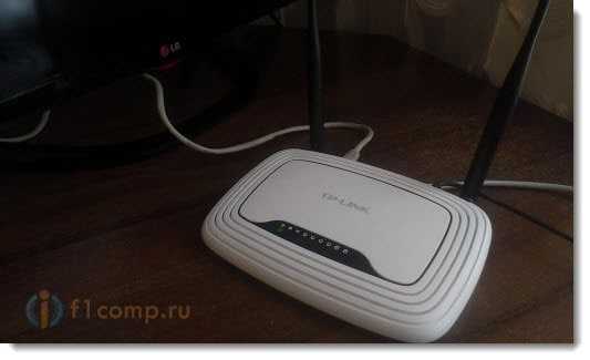
We connect one end of the cable to the router, into the yellow connector (sorry for the photo quality).

On the TV, connect the second end of the cable to the network connector (RJ-45). It would be better if the TV was on.

It should look something like this:
If everything is fine, then immediately after connecting the cable a window should appear on the TV with a message stating that connection to a wired network has been established(it disappears quickly).
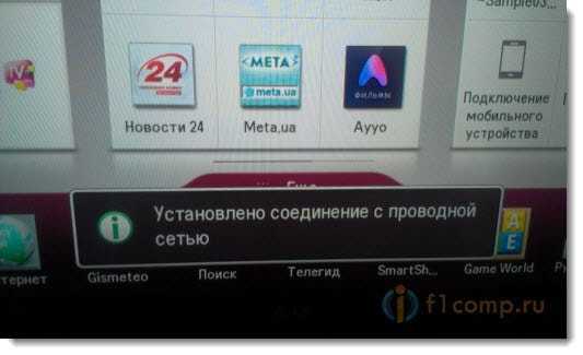
That's it, the Internet on the TV is already working! You can use them all Smart functions TV.
Connect directly using a network cable from your provider
Here almost everything is the same as in the previous method. If your provider uses connection technology “Dynamic IP” (you can check with support), then we just connect the cable to the TV and everything works.
But if technology PPPoE, then this is a little more complicated. For example, on my LG 32LN575U there is no way to configure such a connection. There is only one option, install a router and raise the connection on it. And already connect the TV with a cable or via Wi-Fi.
But, as far as I know, for example, some Samsung TVs can raise PPPoE connection. See the specifications and check with the manufacturer.
Set static IP and DNS on the TV
You may need to set a static IP and DNS when connecting via LAN (the provider can also use this technology), It can be done. I’ll show you how :)
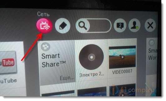
Go to Smart TV and select the network icon (can also be done through settings).
Click the button Set up connection.

Select a button Manual setup.
The cable should already be connected!

Select a button “Wired”.

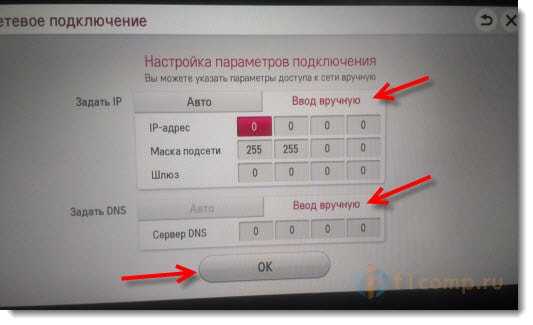
The TV will build a network map and display the result of the Internet connection. Like this (your map may be different, that’s normal):
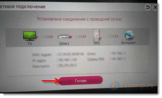
Click Ready. That's it, the wired network with a static IP is configured.
The provider binds by MAC address. Where can I watch MAC on TV?
If your provider links by MAC address y, and the Internet is already connected, for example, to a computer, then connecting it to the TV most likely will not work. It is necessary for the provider to change the binding to the MAC address of the TV.
In this case, we need to find out the MAC address of our TV. This can usually be done in the settings.
In LG 32LN575U tab Support – Inf. about the product/service.

That's all. If you have any questions, ask them in the comments! Best wishes!
Also on the site:
We connect the TV to the Internet via a network cable (LAN) updated: February 7, 2018 by: admin
Any local network consists of several components: computers that you will connect; the cable with which you will connect them and the central device that will control data transfer over the network (switch). This is the minimum set of equipment required to create most local networks. If you want to connect only two computers into a network, you won’t need a switch. But today we will consider the most common option for building a local network: using a “star” topology, when computers are connected to a switch with a twisted pair cable.
Before you begin installing your network, you need to have a clear plan of action. In today's article we will look at the process of designing and installing a small local network. It will not use an enclosure with a patch panel installed; We also don’t need a separate room – a server room, in which, as a rule, an installation cabinet or rack is installed. In our case, connecting active network equipment comes down to easy connection cables to ports on this or other devices. Next, the central node of the network (switch) will need to be located in any suitable location. Now let's talk about everything in order.
1. First, take a look around the room in which the future network will be laid. It wouldn’t hurt to draw the floor plan on a regular piece of paper. Mark on it the places where computers and printers are located, count the number of users on your network. You may want to rearrange your computers.
2. Select the location where the switch will be located. Please note that the distance from the switch to each computer is no more than 90 meters, since at a distance of more than 100 meters the signal in the twisted pair will attenuate (in this case, repeaters are used). The switch should be located near an electrical outlet and away from users. You need to be able to access the switch at all times, so don't place it too far under a desk or behind a cabinet.
3. Now you need to mark the cable route from the switch to each computer. The cable should run along the walls. You can drill holes in the walls using a drill and run the cable through the walls if the computers are located in several rooms. To hide the cable from prying eyes, you can buy special cable boxes. It is not necessary to use such boxes when installing a small local network, but I will still say a few words about them.
The boxes are different and differ mainly only in their sizes. The largest volume of boxes will be required when laying main highways along corridors. Smaller boxes are used for installing cables inside one room. In order to hide the transitions between dissimilar segments of boxes, various decorative adapters and corners of the appropriate size are used. The most optimal option for placing a box with a small amount of cable is the lower part of the wall, approximately 40-60 centimeters from the floor. This allows you to hide the cable line as much as possible, since most of the wall is always filled with some kind of furniture.4. Now calculate the length (in meters) of twisted pair cable required to connect the computers to the switch. It’s better to do it this way: go to the first computer and use a tape measure to measure the length of the cable from of this computer to the location where the switch will be located. Add another 2-3 meters just in case. This is the length of the cable to connect this PC to the switch. Do the same with the second, third, etc. computers. As a result, you will get a list of twisted pair lengths for each computer. Add them together - that's the total length of cable you need to purchase.
By the way, it is more convenient and cheaper to buy twisted pair in a coil of 150-300 meters, of course, if you need that much cable. A coil is a box containing a cable wound on a drum:5. Then inspect each computer to see if it has a network card. Almost any modern computer has a network card integrated into the motherboard. Look at the back wall system unit and find the RJ-45 connector: Laptops also have such a connector: If one of the computers does not have a network card or the built-in one is faulty, then you will need to purchase and install it. The network card is installed in the PCI slot on motherboard system unit: When purchasing a network card, it must come with a driver disk. Write down how many of these cards you will need to purchase.
6. You should also add RJ-45 connectors to your shopping list. For each computer you will have your own piece of cable, at both ends of which RJ-45 connectors will be attached. One of the connectors is inserted into the network card connector, the other into the switch connector.
So, it's time to go to the computer store. What equipment do we need to purchase:
- switch;
- twisted pair cable category 5E;
- RJ-45 connectors – two connectors for each computer;
- network cards (if they are not installed in the computer);
- crimping tool for cutting cables and inserting them into connectors.
After everything necessary has been purchased, we begin installing the equipment and actually laying the network.
First of all, install the purchased network cards in those computers that did not have them. Then don't forget to install drivers for them.
Now let's check the functionality of the network cards on all computers. To do this, turn on each computer - after the system boots, find the “My Computer” icon on the desktop and right-click on it - go to “Properties” - “Hardware” - “Device Manager”. Here, in the “Network Cards” section, the network card installed on the computer should be displayed. It will look the same as in the screenshot (only the name of the board will be different): If in the “Device Manager” there is a yellow question mark on the name of the network card or instead of the name there is the inscription “ Unknown device”, then you need to install (reinstall) the device driver.
If there is no network card in the “Device Manager” at all, then it is either disabled in the BIOS, or incorrectly installed in the connector on the motherboard, or is faulty.
After we have made sure that the network cards on all computers are working, we move on to crimping the cables. You can learn how this is done from my article “How to crimp a twisted pair cable.”
We connect the crimped cables with one end to the connectors of the network cards of all computers, and the other end to the connectors of the switch. We turn on all computers and the switch if they were turned off before.
After this, we need to check the functionality of our network at the physical level (signal level). If everything is in order with this, then we can move on to setting up the computer operating system for working on a local network. Read about this in the article “Instructions for setting up a local network in Windows XP.”
blogsisadmina.ru
What equipment is needed to create a local network
In any organization where there are two or more computers, it is advisable to combine them into a local network. The network allows employees to quickly exchange information and documents with each other, and serves to share shared Internet access, equipment and information storage devices. To connect computers, we need certain network equipment. In today's article we will look at what equipment is used to create a wired local network.
Network equipment – devices that make up a computer network. There are two types of network equipment:
- Active network equipment is equipment that is capable of processing or converting information transmitted over the network. Such equipment includes network cards, routers, and print servers.
- Passive network equipment is equipment used for simple signal transmission at the physical level. These are network cables, connectors and network sockets, repeaters and signal amplifiers.
To install a wired local network, we first need:
- network cable and connectors (called connectors);
- network cards - one in each PC on the network, and two on the computer serving as a server for accessing the Internet;
- a device or devices that ensure the transfer of packets between computers on a network. For networks of three or more computers, you need a special device - a switch that connects all the computers on the network;
- additional network devices. The simplest network can be built without such equipment, but when organizing a shared Internet connection and using shared network printers additional devices can make solving such problems easier.
Now let’s take a closer look at all the equipment listed above:
Network Explorers
This group includes various network cables (twisted pair, coaxial cable, fiber optic).
Coaxial cable is the first cable used to create networks. Its use in building local computer networks has long been abandoned.
Fiber optic cable is the most promising in terms of speed performance, but also more expensive compared to coaxial cable or twisted pair. In addition, the installation of fiber optic networks requires high qualifications, and expensive equipment is needed to terminate the cable. For these reasons, widespread this type I haven't received the cable yet.
Twisted pair is the most common type of cable used today to build local networks. The cable consists of pairs of intertwined copper insulated conductors. A typical cable has 8 conductors (4 pairs), although cables with 4 conductors (2 pairs) are also available. The colors of the internal insulation of conductors are strictly standard. The distance between devices connected by twisted pair cable should not exceed 100 meters. There are several categories of twisted pair cables, which are labeled CAT1 to CAT7. Local Ethernet networks use CAT5 twisted pair cables.
To work with twisted pair cable, RJ-45 connectors are used.

Network cards
Network cards are responsible for transferring information between computers on the network. A network card consists of a connector for a network conductor (usually a twisted pair cable) and a microprocessor that encodes/decodes network packets. A typical network card is a card that plugs into a slot PCI buses. In almost all modern computers, the electronics of the network adapter are soldered directly to the motherboard. Instead of an internal network card, you can use an external USB network adapter: It is a USB-LAN adapter and has similar functions to its PCI counterparts. The main advantage of network USB cards is its versatility: without opening the system unit case, such an adapter can be connected to any PC that has a free USB port. Also, a USB adapter will be indispensable for a laptop in which the only built-in network connector has failed, or there is a need for two network ports.
Network switches
Not so long ago, network concentrators (or, in common parlance, hubs) were used to build local networks. When a network card sends a data packet from a computer to the network, the hub simply amplifies the signal and transmits it to all network participants. Only the network card to which it is addressed receives and processes the packet; the others ignore it. Essentially, a hub is a signal amplifier.
Currently, local networks use switches (or, as they are called, switches). These are more “intelligent” devices, which have their own processor, internal bus and buffer memory. If the hub simply forwards packets from one port to all others, then the switch analyzes the addresses of network cards connected to its ports and forwards the packet only to desired port. As a result, unnecessary traffic on the network is sharply reduced. This allows you to significantly increase network performance and provides higher data transfer speeds in networks with a large number of users. The switch can operate at speeds of 10, 100 or 1000 Mbps. This, as well as the network cards installed on computers, determines the speed of the network segment. Another characteristic of a switch is the number of ports. This determines the number of network devices that can be connected to the switch. In addition to computers, they include print servers, modems, network disk drives and other devices with a LAN interface.
When designing a network and choosing a switch, you need to take into account the possibility of expanding the network in the future - it is better to purchase a switch with a slightly larger number of ports than the number of computers in your network on this moment. In addition, one port must be kept free in case it is combined with another switch. Currently, switches are connected by ordinary twisted pair cable of the fifth category, exactly the same one that is used to connect each computer on the network to the switch.
There are two types of switches - managed and unmanaged. Managed ones have additional functionality. Thus, it becomes possible to manage the switch using the web interface, combine several switches into one virtual one with its own packet switching rules, etc. The cost of managed switches is much higher than the cost of unmanaged switches, which is why unmanaged switches are used in small and medium-sized networks.
Additional network equipment
On a local network you can use various optional equipment, for example, to connect two networks or to protect the network from external attacks. Let's briefly look at the network equipment that is used to build computer networks.
A print server, or print server, is a device that allows you to connect a printer that does not have its own network port to the network. Simply put: a print server is a box to which a printer is connected on one side, and a network cable on the other side. In this case, the printer becomes available at any time, since it is not tied to any computer on the network. There are print servers with different ports: USB and LPT; There are also combined options. The repeater is designed to increase the distance network connection by amplifying the electrical signal. If you use a twisted pair cable more than 100 meters long in your local network, repeaters should be installed in the cable break every 100 meters. Repeaters are usually powered via the same cable. Using repeaters, you can connect several separate buildings with a network cable.  A router (or router) is a network device that, based on information about the network structure, uses a certain algorithm to select a route for sending packets between different network segments.
Routers are used to connect networks of different types, often incompatible in architecture and protocols (for example, to connect Ethernet to a WAN network). The router is also used to provide access from a local network to the global Internet, while performing the functions of a firewall. A router can be presented not only in hardware, but also in software. Any computer on the network that has the appropriate software, can serve as a router.
blogsisadmina.ru
Local wired network (LAN) is the basis of the home information space and multimedia.. Criteria for constructing a LAN.. Wireless connection- pros and cons.. Fast Ethernet technology.. Structural scheme LAN networks.. Star network topology.. Selecting LAN network equipment.. Router (router).. Setting up a router.. Built-in ADSL modem.. WI-FI access point.. Switch or hub?.. Characteristics D -Link DSL-6740U.. Characteristics of D-Link DIR-615/K1A.. UTP Cat 5e cable (dual twisted pair).. Technical specifications.. Example of a local network project.. Equipment layout diagram.. LAN network wiring diagram. Today it is impossible to imagine a house, apartment or office without numerous complex instruments and devices, communication with which is already becoming a problem in our time.
A person voluntarily becomes dependent on computers, the Internet, audio and video systems, remote controls, security systems and other electronic devices that give us new opportunities and conveniences, but take up all our free time. To cope with this problem and make life as convenient and comfortable as possible, you need to set yourself new tasks that can be implemented using smart home technologies.
The most popular systems in a modern home are:
Wired local network Multimedia Lighting control Heating and climate control Security and fire alarms Video surveillance Intercom and access control. The implementation of smart home systems can be comprehensive (in the case of major renovations or construction of a new house) or partial. It all depends on the priorities for choosing certain systems and the possibilities of their implementation. Today we will look at a wired local network.
Wired local area network (LAN)
 A wired local area network (Local Area Network) serves for a centralized connection to the Internet and communication of computers and various peripheral devices in the house with each other. In fact, the local network is the basis of the home information space and multimedia. By designing and building a computer, telephone and television network in your home, you will provide all multimedia and computer equipment in the house. It always makes sense to consider and design these networks together.
 Why wired?
The choice is always yours. I'm just emphasizing that when possible, you need to choose wired technologies. At every opportunity I try to justify this choice.
Wired vs Wireless Connection: Pros and Cons
On the plus side wireless equipment You can note a large number of connections, which is limited only by the transmission speed per user. Also – connectivity mobile devices(smartphones, communicators, tablets), as well as freedom of movement indoors. Perhaps that's all.
Disadvantages: wireless technologies are usually more complex in design and, accordingly, less reliable than wired ones. For an unskilled user, this can result in difficulties during operation, in particular, in diagnosing and troubleshooting problems. This is especially true as the number of devices increases.
The wireless connection will also be slower. No one will argue that the technical indicators of the cable signal level are higher than the radio signal. Speed wireless communication inferior to wired ones by almost half, both for objective reasons (wireless data transfer protocol is slower) and due to external interference (metal wall fittings, interference from home electronics, etc.). There is always equipment in the house that requires speed and quality connections - for example, the same multimedia HD media players, information from which can be requested from several devices (computers, TVs, etc.) If you want to watch a BluRay quality movie on a projector high resolution, Then Wi-Fi speed using even modern equipment may not be enough.
In terms of cost, wireless equipment will cost one and a half times more than its wired counterparts.
Electromagnetic “pollution” and mutual interference of wireless equipment have also not yet been canceled.
Therefore, before using a network connection via wireless technology Wi-Fi, you need to weigh the pros and cons and make sure that you can’t do without wireless equipment. Whenever possible, it is best to minimize harmful emissions in the workspace where you spend a significant portion of your time. In practice, a home local network is most often combined. For example, desktop computers can be connected to the network using wires using Ethernet technology, and various mobile devices (laptops, tablets, smartphones) can be connected via wireless Wi-Fi standard.
LAN construction criteria
When choosing a network standard and network topology, the decisive factor is the data transfer speed and the possibility of further expansion of the system. These conditions are fully met by wired Ethernet technology. This standard provides parallel data transfer. This means that in Ethernet, data is not transmitted to all devices one by one (as in RS-485), but directly to the desired device. This significantly increases the speed of information transfer. Besides, this protocol Provides compatibility with existing network devices and future developments. Using the Ethernet protocol, you can be sure that the local network being built will be able to develop in the future. There are currently three specifications differing in transmission speed:
Classic Ethernet (10 Mbit/s); Fast Ethernet (100 Mbit/s); Gigabit Ethernet(1 Gbit/s).
For a home information network, the most optimal in terms of price/quality/complexity ratio is the “star” topology and the 802.3 100Base-TX network standard. This is 100 Mbit Ethernet on dual twisted pair, which in terms of price/performance ratio is still unrivaled. The basis of the network is a switch, to which network devices are connected by cables with a maximum length of 100 m.
The big advantage of the star topology is its scalability, that is, further expansion, and this is what is very important in home networks. This is achieved by connecting each computer (or other device) to a dedicated Ethernet port of a hub or switch. That is, one switch port – one computer. Typically, the number of Ethernet ports on a switch is selected with a reserve, so it is always possible to connect a new device to a spare port. Accordingly, each computer must be equipped with a network adapter with an RJ-45 connector.
The task is made easier by the fact that all modern computers and laptops already have a built-in Ethernet port.
Equipment selection criteria
All home local networks are designed according to the same principle: user computers equipped with network adapters are connected to each other through special switching devices. Routers (routers), concentrators (hubs), switches (switches), access points and modems can act in this capacity.
The main component of a home local network is a router or router, which is a multifunctional device with a built-in operating system that has at least two network interfaces: 1. LAN (Local Area Network) - used to create an internal (local) network, which consists of your computers devices. 2. WAN (Wide Area Network) – used to connect a local network (LAN) to the worldwide global network- Internet.
Routers are divided into two classes based on the type of external connection: Ethernet or ADSL. Accordingly, they have a WAN port or ADSL port for connecting the provider’s cable and up to four LAN ports for connecting network devices using Ethernet technology.
The router for connecting to an ADSL line has a built-in ADSL modem.
Wireless routers, among other things, have a built-in Wi-Fi access point for connecting wireless devices. The number of equipment that can simultaneously access the network using Wi-Fi technology can, in principle, number in the dozens. Considering that the channel's frequency band is divided among all connected clients, throughput communication channel decreases with increasing their number.
When the number of connected computers does not exceed four, the router is the only component that is needed to build a local network, since there is simply no need for the rest.
When choosing a router for your home network, it is preferable to choose a router using IEEE 802.11n technology, which provides better performance and signal coverage. In addition, these routers support VPN user and have a built-in USB port that can be used to connect a flash drive, printer or external hard drive (NAS).
Before purchasing a router, you need to check with your provider in advance what type of connection you will use and what additional equipment you will need for this. The delivery package of routers should include an external power adapter and an RJ-45 cable, and for models with an ADSL port, an additional RJ-11 cable and a splitter.
It is useful to consult with the technical support of the provider regarding technical requirements to the client’s equipment, in terms of its compatibility with the provider’s servers. Having received professional information, you can more intelligently make your choice from the router models available for sale.
About the amount of equipment. If you are designing a local network for a 2- or 3-story cottage, then you won’t be able to get by with just one Wi-Fi router. To ensure a sufficient level wireless signal you will have to build a distributed Wi-Fi network consisting of several routers or access points. To reduce the load on your wireless network and increase data transfer speeds, you can Wi-Fi access leave it only for mobile devices, and organize computers (possibly laptops) using wired access.
One more point: today buying a router without Wi-Fi support is simply pointless. The difference in the cost of good wired router and its wireless counterpart is quite small. Even if you do not plan to use the Wi-Fi module in the router in the near future, you can disable it. When such a need arises (for example, a device with Wi-Fi connection), you can always enable it in your router Wi-Fi module and start using wireless Internet.
There are quite a lot of recommendations on the Internet for setting up routers, including detailed instructions for specific models. Here I would like to note the following: Taking into account the interests of users, developers have long made it easier to configure router settings using built-in software for step-by-step configuration, making it accessible even to beginners.
In most cases, when you first enter the router menu, a wizard is launched that offers quick step-by-step setup its main parameters. This saves novice users from searching required options among the many sections of the menu.
If necessary, the installation wizard can be launched manually using the menu item in different options: Quick Setup, Setup Wizard, etc.
You just need to take into account that in certain situations, connecting to the Internet may require special settings, the ability to enter which is simply not possible in the wizard mode. In these cases, you will have to contact manual mode setting parameters.
Switches
If you need to build a more extensive wired network, then four LAN ports of the router will not be enough. In this case, an additional switching device is connected to one of the router ports - a hub or switch.
Unlike a router, switches and hubs have only one network interface - LAN and are used only for scaling (expanding) local networks.
To create a wired Ethernet network, it is better to use a switch (switch) rather than a concentrator (hub). The switch analyzes traffic outgoing from computers and forwards it only to those to whom it is intended. The hub simply repeats any traffic to all ports. As a result, the performance of an Ethernet network on hubs is highly dependent on the overall load. The network on the switch is free from this drawback.
Previously, you had to choose: either price or performance, since hubs were significantly cheaper than switches. Now both types of devices are almost equal in price, so the choice in favor of the switch is beyond doubt.
Which switch should you choose?
There are many models and types of network switches available these days, and their prices and features vary greatly. When choosing, you must proceed from the minimum cost of a device that will meet your requirements for data transfer speed and number of ports. The dimensions of the switch may also have a certain significance.
Speed of operation For a home local network, in terms of price/performance ratio, Fast Ethernet (100 Mbit/s) remains optimal.
Number of ports
This indicator characterizes the number of network devices that can be connected to this switch. In many ways this parameter determines the price of the device.
The choice depends on the number of users of your future network. You need to add 1-2 ports in reserve to the number of users.
In models aimed at home use, the number of Ethernet ports is usually 5 or 8. If at some point the number of switch ports is no longer enough to connect all devices, you can connect another switch to it. So you can expand home network as much as you like.
The 100Base-TX (Fast Ethernet) transmission medium uses unshielded UTP Cat 5e cable (dual twisted pair), with one pair used to transmit data and the other to receive it. Cat 5e cable type 100BASE-T4 (quad twisted pair) can be used: two redundant pairs can be used in the future to upgrade the network to 1000 Mbps (Gigabit Ethernet).
Shielded cables (FTP, STP, SFTP) are used when laying trunk lines and in industrial premises with large electromagnetic fields. Home local networks typically use unshielded UTP cable.
For the telephone network, UTP Cat 3 cable (dual twisted pair) is used.
Is it possible to use one of the pairs of four-pair cables used for computer networks to wire a telephone in order to save money?
It's possible, but it's unlikely to be necessary. Why create additional installation problems for yourself? It is best to use separate unshielded twisted pair wiring, as this significantly increases noise immunity telephone communication. In addition, the redundant twisted pair of the Cat 3 cable may be useful in the future for repairing a damaged pair or for connecting additional equipment.
Twisted pair cores in cables come in two types: single conductor and multi-core. The diameter of the cores in single-core twisted pairs is 0.51 mm. Cables with single-core conductors are used for installing networks in boxes, cable ducts and on walls. With stranded conductors, the cable is used only where it can be subject to frequent bending, for example, to connect a computer to an RJ45 socket (patch cord).
In a star topology, all cables from network devices converge to the switch, and sockets with RJ45 sockets are installed at opposite ends of the cables. Both cables and sockets must be Category 5e or 6.
All cable sections should be no more than 100 meters - only in this case is the stable operation of the network guaranteed. Please note that the maximum cable segment length requirement of 100 m includes the entire length of the cable connecting the computer to the switch. If the cabling ends on the computer side with a wall socket, and on the switch side with a cross-panel, then the length of the segment must include patch cables connecting the computer to the socket and the cross-panel to the switch. It is recommended that the maximum length for the internal wiring cable segment be 90 m, leaving 10 m for patch cables. Of course, all cables must be solid, no “twists” are allowed. Example of a local network project The basis for creating any project is the technical specification (TOR). Ideally, a detailed technical specification for the design should be provided by the customer. In practice, especially for private households, the designer actually has to participate in the collection of initial data and development of technical specifications, since without a full understanding of the features of the object and consultation with the customer, it is impossible to complete the project.
An approximate sequence of designer actions when drawing up terms of reference on designing a “smart” home was discussed in detail in the article “From classical electrics to a smart home.”
Let's consider the actions of the designer on the basis of the technical specifications agreed with the customer for the design of a local network for a two-story country house with an area of 200 m2. As noted, computer, telephone and television networks are combined in one project. Initial data 1. There is a floor plan of the house. 2. High-speed Internet access – via dedicated ADSL3 line. The mode of access to the city PBX is pulse4. Number of Ethernet sockets – 6 5. Quantity telephone sockets– 1 6. The following must also be provided: WI-FI points access to connect wireless devices. Spare port for additional wired connection 1 computer.7. Television: terrestrial + satellite TV
8. Number of television sockets TV+SAT – 6
Equipment placement
Although we're talking about about a relatively small local network, but taking into account the equipment of telephone and television networks and two levels (floors), it makes sense to use low-current mounting cabinets, and to connect network devices - appropriate sockets. It is convenient to use a power outlet because when you change the location of the computer (or TV), you do not need to extend the entire cable segment - you just need to create a new patch cord connecting the device to the outlet. The house plan determines the locations of the proposed placement of mounting cabinets, computers, telephones and television receivers. The placement of equipment on the 1st floor plan is shown in Fig. 1.  Equipment selection
Internet connection will be provided via a dedicated ADSL channel in telephone line, leading from the telephone exchange to the house. This means that when choosing equipment, we need to provide for the presence of an ADSL modem.
Wireless devices require at least two WI-FI access points (2 floors). The task is made easier by the fact that the number of Net outlets on each floor does not exceed three. This allows you to minimize the amount of equipment required to build a local network. A home LAN network for a two-story house with an area of 200 m2 can be made using an ADSL router and an Ethernet switch. The block diagram of the network is shown in Fig. 2.  Main characteristics of the devices used: D-Link DSL-6740U Device type: DSL modem, router, Wi-Fi access point Support: VDSL2, ADSL2 Wireless standard: 802.11b/g/n, frequency 2.4 GHz Max. speed wireless connection: up to 300 Mbit/s (802.11n) Encryption technology WPA/WPA2 Switch: 4xLAN Port speed: 100 Mbit/s Dimensions (WxDxH): 228x175x40 mm Weight: 460 g Contents: Router, power adapter, RJ-45 cable, RJ-11 cable, splitter, disk with software.
D-Link DIR-615/K1A
Device type: Wi-Fi access point, Switch Max. wireless connection speed, Mbit/s - 300 Wireless standard: 802.11n, frequency 2.4 GHz Data encryption: WPA, WPA2 Number of Ethernet ports - 4 Port speed: 100 Mbit/s Dimensions (DxWxH): 117x193x31 mm Weight: 940 g Contents: Router, network adapter, RJ-45 cable, 2 external antennas, disk with software.
Network diagram
It is best to place the installation (low-current) cabinet in a place where it is most convenient to route cables from all rooms and ensure reliable coverage of the WI-FI access point. In this project - in the hall of the first floor. You will also need to run a cable from the provider there.
The second mounting cabinet is installed in the second floor hall. The wiring cabinets also provide electrical outlets for powering the routers.
Separate cables for the Ethernet network, telephone and television diverge from the low-current cabinet in a star-shaped manner. At the ends of these cables, separate sockets are installed for each system: telephone and computer (symmetrical) and television (coaxial). The living room has a double socket (telephone + computer).
Thus, three cable systems and three types of sockets are formed in the building. This scheme is more reliable and convenient for installation - each cable system can be installed almost independently.
The wiring diagram for telephone, television and Ethernet networks is shown in Fig. 3. Fig.3 Equipment installation
Installing and connecting routers does not cause any difficulties. The main thing is to determine the place in the installation cabinet where it will be located and secure it well. For mounting in a vertical position, there are special shaped grooves in the bottom of the router, by which it is suspended and fixed in a closet or on the wall. Some models are equipped with special stands or panels for vertical placement.
If you liked the article and you appreciate the efforts put into this project, you have the opportunity to make a contribution to the development of the site on the “Project Support” page.
Continued in the articles “ Telephone network in the house - a solution option" and "Example of a television SAT/TV network."
vgs-design-el.blogspot.ru
What cables are used in local networks
Today, a wired connection is one of the fastest and most reliable. Data transfer speeds reach 100 Mbps, although the theoretically available speed is 200 Mbps. Most often, twisted pair cable is used in local networks. But if the distance is more than 100 meters, if electromagnetic pollution is increased, then it is better to use other types of cable. There are three types: coaxial, twisted pair and fiber optic.
Coaxial

This cable consists of two insulated conductors, where one is a copper core and the second is a sheath. It is almost never used for local networks, although it is found in low-speed connections. It can be seen as antenna wires.
twisted pair

This is one or more pairs of insulated conductors twisted together. This design reduces external and internal effects from inducing currents.
Divided by degree of protection:
- UTP (unprotected);
- F/UTP (foil);
- STP (protected);
- S/FTP (foil shielded);
- SF/UTP (unprotected shielded).
Also, the twisted pair is marked from CAT1 to CAT7. More high category means a higher quality product with better performance. The most used is twisted pair cable UTP 5e, that is, improved CAT 5e with a frequency of 125 MHz.
Fiber optic

The most modern, fast and reliable way to transfer data. High speed, theoretically up to 200 Mbit/s. In addition, it is indifferent to electromagnetic interference. It has two varieties - single-mode and multi-mode, differing in the modes of photon transmission. The price of components and the complexity of installation significantly reduce the desire to use fiber optics as a cable for local networks, but its popularity is growing.
We will build modern LANs (LAN, WLAN) based on Gigabit Ethernet local network network technology, providing a transfer speed of 1 Gb/s.
Network installation, basic principle.
Cabling.| These measures can reduce signal attenuation in the cable: | |
| as few bends as possible with a small radius of curvature; fewer connections; |
|
| The basic rules for laying cables are determined by the requirements of ISO/IEC 11801 and ANSI/TIA/EIA-568A standards.
Twisted pair wiring has a number of features. For example: twisted cable UTP pair, has a maximum permissible bending radius of eight outer cable diameters. Stronger bending leads to damage to the cable insulation and an increase in the intensity of external noise. |
|
When buying a cable (twisted pair), it is important to know!
Why is copper important? Examples.
* Categories UTP, FTP, STP twisted pair cables used in networks »
* Local network topologies »
* Types of passive fiber optic equipment »
Ethernet technologies in networks.
| Levels | Ethernet 10BASE-T | Fast Ethernet | Gigabit Ethernet |
| 1. End user (between the end user device and the device working group) | Provides connection: ▪ between end-user devices and user-level switches |
Provide high-performance (PC) server access at 100 Mbps | |
| 2. Workgroup level (connection of a workgroup device to the backbone) | At this level, as a rule, they are not used | Provides connection: ▪ between the end user and the working group; ▪ a block of servers and a backbone |
Provide high-speed links between: ▪ working group and highway; ▪ high-speed channels to a block of servers |
| 3. Trunk level | At this level, as a rule, they are not used | Connections with applications that require low to medium volume bandwidth | Provide connections between high-speed highways and network devices |
| In today's networks, although it is possible to provide Gigabit Ethernet connections from the backbone all the way to the end user, the cost of cables and switch ports can make such a solution impractical. Before making a decision in such a situation, it is necessary to correctly determine the needs of the network. For example, a network operating at traditional Ethernet speeds can easily become congested if new generation software products are running on it: multimedia, graphic applications and database management systems. In general, Ethernet technologies can be used in territorial LAN networks in several ways below. |
At the user level, fairly high performance can be achieved using Fast Ethernet connections. Fast Ethernet and Gigabit Ethernet technologies can be used for clients or servers that require high bandwidth. |
Use the repeater as a signal amplifier!
| Amplified by the switch, data packets gradually fade and become distorted. Therefore, the signal can pass through no more than four switches. The maximum distance over which a twisted pair cable can be laid using network switches, is 900 meters. | |
 |
if the distance over which the network needs to be extended exceeds the capabilities of four switches, it is necessary to use a repeater. The repeater recalculates the data packets, which allows you to connect four more switches. using repeaters and network switches, you can lay twisted pair cable over an almost unlimited distance; in the diagram below, switch/hab are used, since they can also be used as a repeater. |
Scheme - we lay a LAN over 300 meters.

Scheme of a local area network for an office.

Checking (continuity) of the network cable.
If possible, lay the network cable in a metal or plastic pipe. This will protect it from accidental damage and rodents.
How to find the same cable, wire or core in a pile of wires?
 |
Analog tone generator for sending tones and wire tracking on inactive networks, and in particular for identifying pairs using SmartTone® technology. Clamps with angled piercing pins make wires easier to access, and the RJ-11 connector is ideal for use in telephone jacks. The powerful speaker on the network sensor allows you to hear sound through drywall, wood and other obstacles, making locating wires quicker and easier. You can send a powerful tone signal over a distance of up to 16 kilometers, - practically anyone cable! |
| A tone generator is convenient when a huge network is being laid, where there are a lot of different cables and wires, which, in addition, also need to be labeled. This is where this “magic” device comes to our aid! | |
Twisted pair crimping.
 |
 |
 |
 |
| rj-45 cat.5 | crimper | stripper | twisted couple |
  |
 |
||
| rj-45 cat.6 (23AWG) | rj-45 cat.6, 6a, 7 (22/23AWG) | ||
Compressed straight patch cord (Internet over two twisted pairs)
 |
 |
 |
 |
 |
 |
 |
 |
Crossover in computer networks (crossover)- a crimped patch cord according to the EIA/TIA-568A - EIA/TIA-568B scheme for direct connection of network cards (network card, network adapter or Ethernet adapter) of two computers, i.e. is a patch cable or patch cord that connects two computers on a local network directly to each other without the use of network concentrators (hubs).
During the development of local networks, quite a lot of types of cables have appeared, and all of them are the result of increasingly complex standards requirements. Some of them are already a thing of the past, and some are just beginning to be used, and thanks to them, it has become possible to achieve the high data transfer speed that we need so much.
In today's article I will talk about the main types of cables and connectors that have become widespread in the construction of wired local networks.
1)Coaxial cable is one of the first conductors used to create networks. Coaxial cable consists of a central conductor encased in thick insulation, a copper or aluminum braid, and an outer insulating sheath.
To work with coaxial cable, several connectors of different types are used:
- -BNC connector. Installed at the ends of the cable and used to connect to the T-connector and barrel connector.
- -BNC T-connector. It is a kind of tee that is used to connect a computer to the main line. Its design contains three connectors at once, one of which is connected to the connector on the network card, and the other two are used to connect the two ends of the trunk.
- -BNC barrel connector. With its help, you can connect the broken ends of the highway or sharpen part of the cable to increase the radius of the network and connection additional computers and other network devices.
- -BNC terminator. It is a kind of stub that blocks further propagation of the signal. Without it, the functioning of a network based on coaxial cable is impossible. A total of two terminators are required, one of which must be grounded.
Coaxial cable is quite susceptible to electromagnetic interference. Its use in local computer networks has long been abandoned.
Coaxial cable has become mainly used to transmit signals from satellite dishes and other antennas. The coaxial cable received a second life as a backbone conductor of high-speed networks that combine the transmission of digital and analog signals, for example, cable television networks.
2) Twisted pair is currently the most common cable for building local networks. The cable consists of pairs of intertwined copper insulated conductors. A typical cable has 8 conductors (4 pairs), although cables with 4 conductors (2 pairs) are also available. The colors of the internal insulation of conductors are strictly standard. The distance between devices connected by twisted pair cable should not exceed 100 meters.
Depending on the presence of protection - an electrically grounded copper braid or aluminum foil around the twisted pairs, there are types of twisted pair:
- -Unshielded twisted pair (UTP, unprotected twisted pair). Apart from conductors with their own plastic protection, no additional braids or grounding wires are used:
- -Foiled twisted pair (F/UTP, foil twisted pair). All pairs of conductors of this cable have a common foil shield:
- -Shielded twisted pair (STP, protected twisted pair). In a cable of this type, each pair has its own braided shielding, and there is also a common mesh screen for all:
- -Screened Foiled twisted pair (S/FTP, foil shielded twisted pair). Each pair of this cable is in its own foil braid, and all pairs are placed in a copper shield:
- -Screened Foiled Unshielded twisted pair (SF/UTP, unprotected shielded twisted pair). Characterized by a double shield of copper braid and foil braid:
There are several categories of twisted pair cables, which are labeled CAT1 to CAT7. The higher the category, the higher quality the cable and the better performance it has. Local computer networks of the Ethernet standard use twisted pair cable of the fifth category (CAT5) with a frequency band of 100 MHz. When laying new networks, it is advisable to use an improved CAT5e cable with a frequency band of 125 MHz, which better transmits high-frequency signals.
To work with a twisted pair cable, an 8P8C (8 Position 8 Contact) connector, called RJ-45, is used.
3) Fiber optic cable is the most modern data transmission medium. It contains several flexible glass light guides protected by heavy plastic insulation. The data transfer speed over optical fiber is extremely high, and the cable is absolutely free from interference. The distance between systems connected by optical fiber can reach 100 kilometers.
There are two main types of fiber optic cable - single-mode and multi-mode. The main differences between these types relate to different modes passage of light rays in the cable. To crimp a fiber optic cable, many connectors and connectors of different designs and reliability are used, among which the most popular are SC, ST, FC, LC, MU, F-3000, E-2000, FJ, etc.: The use of fiber optics in local networks is limited by two factors. Although the optical cable itself is relatively inexpensive, prices for adapters and other equipment for fiber optic networks are quite high. Installation and repair of fiber optic networks requires high qualifications, and cable termination requires expensive equipment. Therefore, fiber optic cable is mainly used to connect segments of large networks, high speed access to the Internet (for providers and large companies) and data transmission over long distances.
In wired local networks, a special cable called “twisted pair” is used to transmit signals. It is called that because it consists of four pairs of copper strands twisted together, which reduces interference from various sources.
Figure 2 - Twisted pair
In addition, the twisted pair has a common external dense insulation made of polyvinyl chloride, which is also very little susceptible to electromagnetic interference. Moreover, on sale you can find both an unshielded version of the UTP (Unshielded Twisted Pair) cable and shielded varieties that have additional screen from foil - either common for all pairs (FTP - Foiled Twisted Pair), or for each pair separately (STP - Shielded Twisted Pair).
Using a modified twisted pair cable with a screen (FTP or STP) at home only makes sense when there is high interference or to achieve maximum speeds with a very long cable length, which should preferably not exceed 100 m. In other cases, a cheaper unshielded UTP cable, which can be found, will do at any computer store.
Twisted pair cable is divided into several categories, which are marked from CAT1 to CAT7. But you shouldn’t be immediately afraid of such diversity, since for building home and office computer networks, mostly unscreened cables of the CAT5 category or its slightly improved version CAT5e are used. In some cases, for example, when the network is laid in rooms with large electromagnetic interference, you can use a sixth category cable (CAT6), which has a common foil screen. All of the categories described above are capable of providing data transmission at speeds of 100 Mbit/s when using two pairs of cores, and 1000 Mbit/s when using all four pairs.
Crimping schemes and types of network cable (twisted pair)
Twisted pair crimping is a crimping procedure. special connectors at the ends of the cable, which use 8-pin 8P8C connectors, which are usually called RJ-45 (although this is somewhat misleading). In this case, the connectors can be either unshielded for UTP cables or shielded for FTP or STP cables.

Figure 3 - Connectors
Avoid purchasing so-called plug-in connectors. They are designed for use with soft stranded cables and require some skill to install.
To lay the wires, 8 small grooves are cut inside the connector (one for each core), above which metal contacts are located at the end. If you hold the connector with the contacts up and the latch towards you, then the first contact will be on the left, and the eighth on the right. Pin numbering is important in the crimping procedure, so remember this.
There are two main schemes for distributing wires inside connectors: EIA/TIA-568A and EIA/TIA-568B.

Figure 4 - Network cable
When using the EIA/TIA-568A circuit, wires from pins one to eight are laid out in the following order: White-Green, Green, White-Orange, Blue, White-Blue, Orange, White-Brown, and Brown. In the EIA/TIA-568B circuit, the wires go like this: White-Orange, Orange, White-Green, Blue, White-Blue, Green, White-Brown and Brown.
For the manufacture of network cables used for connecting computer devices and network equipment among themselves in various combinations, there are two main cable crimping options: straight and crossover (crossover). Using the first, most common option, cables are made that are used to connect the network interface of a computer and other client devices to switches or routers, as well as connect modern network equipment to each other. The second, less common option is used to make a crossover cable, which allows you to directly connect two computers through network cards, without the use of switching equipment. You may also need a crossover cable to connect old switches into a network via up-link ports. computer software network
To make a straight network cable, you need to crimp both ends in the same way. In this case, you can use either option 568A or 568B (used much more often).

Figure 5 - Crimping procedure for straight cable (1 Gbit/s)
It is worth noting that to make a straight network cable it is not at all necessary to use all four pairs - two will be enough. In this case, using one twisted pair cable, you can connect two computers to the network at once. Thus, if high local traffic is not planned, the wire consumption for building a network can be halved. However, keep in mind that at the same time, maximum speed Data exchange on such a cable will drop 10 times - from 1 Gbit/s to 100 Mbit/s.

Figure 6 - Procedure for crimping a straight cable (100 Mbit/s).
As can be seen from the figure, in this example the Orange and Green pairs are used. To crimp the second connector, the place of the Orange pair is taken by Brown, and the place of Green by Blue. In this case, the connection diagram to the contacts is preserved.
To make a crossover cable, one end must be crimped according to scheme 568A, and the other - according to scheme 568B.

Figure 7 - Procedure for crimping a crossover cable (100 Mbit/s)
Unlike a straight cable, all 8 cores must always be used to make a crossover. At the same time, a crossover cable for data exchange between computers at speeds of up to 1000 Mbit/s is manufactured in a special way.

Figure 8 - Crimping procedure for crossover cable (1 Gbit/s)
One end of it is crimped according to the EIA/TIA-568B scheme, and the other has the following sequence: White-green, Green, White-orange, White-brown, Brown, Orange, Blue, White-blue. Thus, we see that in circuit 568A the Blue and Brown pairs have swapped places while maintaining the sequence.
Finishing the conversation about circuits, let's summarize: by crimping both ends of the cable according to the 568V circuit (2 or 4 pairs), we get a direct cable for connecting the computer to a switch or router. By crimping one end according to circuit 568A and the other according to circuit 568B, we get a crossover cable for connecting two computers without switching equipment. A special feature is the production of gigabit crossover cable, where a special circuit is required.
Crimping a network cable (twisted pair)
For the cable crimping procedure itself, we will need a special crimping tool called a crimper. The crimper is a pliers with several working areas.

Figure 9 - Crimping scissors
In most cases, knives for cutting twisted pair wires are placed closer to the tool handles. Here, in some modifications, you can find a special recess for stripping the outer insulation of the cable. Further, in the center of the working area, there are one or two sockets for crimping network (marking 8P) and telephone (marking 6P) cables.
Before crimping the connectors, cut a piece of cable to the required length at a right angle. Then, on each side, remove the common outer insulating sheath by 25-30 mm. At the same time, do not damage the own insulation of the conductors located inside the twisted pair.
Next, we begin the process of sorting the cores by color, according to the selected crimping pattern. To do this, unravel and straighten the wires, then arrange them in a row in in the right order, pressing tightly together, and then trim the ends with a crimper knife, leaving approximately 12-13 mm from the edge of the insulation.

Figure 10 - Cable
Now we carefully place the connector on the cable, making sure that the wires do not get mixed up and that each of them fits into its own channel. Push the wires all the way until they rest against the front wall of the connector. With the correct length of the ends of the conductors, they should all fit into the connector all the way, and the insulating sheath must be inside the housing. If this is not the case, then remove the wires and shorten them somewhat.

Figure 11 - Correct and incorrect crimping.
After you have placed the connector on the cable, all that remains is to fix it there. To do this, insert the connector into the corresponding socket located on the crimping tool and smoothly squeeze the handles until they stop.
Of course, it’s good when you have a crimper at home, but what if you don’t have one, but you really need to crimp the cable? It is clear that you can remove the outer insulation with a knife, and use ordinary wire cutters to trim the cores, but what about the crimping itself? In exceptional cases, you can use a narrow screwdriver or the same knife for this.
Place a screwdriver on top of the contact and press it so that the teeth of the contact cut into the conductor. It is clear that this procedure must be done with all eight contacts. Finally, push the central cross section to secure it in the cable insulation connector.
And finally, I’ll give you a little advice: Before crimping the cable and connectors for the first time, buy with a reserve, since not everyone can perform this procedure well the first time.