Breadboard circuits for beginners. Development boards
Let's look at the design and purpose of solderless breadboards. What is their advantage over other types of assembly, and how to work with them, as well as what circuits a beginner can quickly assemble with them.
Background
The first problem that a radio amateur faces is not even a lack of theoretical knowledge, but a lack of funds and knowledge about installation methods electronic devices. If you don’t know how this or that part works, this will not prevent you from connecting it according to the electrical circuit diagram, but in order to clearly and efficiently assemble the circuit, you need a printed circuit board. Most often they are made using the LUT method, but laser printer Not everyone has it. Our fathers and grandfathers painted the boards by hand with nail polish or paint, and then etched them.

Here the beginner is faced with the second problem - the lack of etching reagents. Yes, of course, ferric chloride is sold in every radio store electronic components, but at first there is so much to acquire and study that it is simply difficult to pay attention to the technology of etching boards made of foil PCB or getinax. And not only for beginners, but also for experienced radio amateurs, sometimes it makes no sense to etch a board and spend money on an unfinished product at the stages of its adjustment.

To avoid problems with finding ferric chloride, PCB, a printer and not to get punished by your wife (mother) for unauthorized use of an iron, you can practice installing electronic devices on solderless breadboards.
What is a solderless breadboard?
As the name suggests, this is a board on which you can assemble a device prototype without using a soldering iron. The layout - as it is popularly called - is present in stores different sizes and the models are slightly different in layout, but the principle of operation and their internal structure are the same.
The development board consists of a housing made of ABS plastic, in which there are detachable connections that resemble double metal bars between which the conductor is clamped. On the front part of the case there are holes, numbered and marked, into which you can insert wires, microcircuit legs, transistors and other radio components in cases with leads. Take a look at the picture below, where I depicted all this.

On the considered printed circuit board, the outer two columns of holes on each side are combined vertically with common buses, from which the positive bus of the power supply and the minus (common bus) are usually formed. Usually indicated by a red and blue stripe along the edge of the board, plus and minus, respectively.
The middle part of the board is divided into two parts, each part is connected in a row of five holes in a row on this particular board. The figure shows a schematic connection of the holes (black solid lines).

The internal structure of the board is shown in the figure below. Double busbars clamp the conductors, as illustrated. Bold lines indicate internal connections.

In the English-speaking environment, such boards are called Breadboard, which is the name by which you can find it on aliexpress and similar online stores.
How to work with it?
Simply insert the legs of electronic components into the holes, connecting the parts together according to horizontal lines, and from the extreme vertical ones you supply power. If you need a jumper, they often use special ones with thin plugs at the ends; in stores they can be found under the name “dupont jumpers” or jumpers for Arduino; by the way, you can also insert it into such a breadboard and assemble your projects.

If the size of one breadboard is not enough for you, you can combine several, they are like puzzles inserted into each other, pay attention to the first picture in the article, the circuit is assembled on two connected boards. There is a spike on one of them, and a recess on the other, beveled from the outer part to the board body so that the structure does not fall apart.

Assembly simple circuits on a breadboard
It is important for a novice radio amateur to quickly assemble the circuit to make sure it works and understand how it works. Let's look at what different circuits look like on a breadboard.

Scheme symmetrical multivibrator It is recommended as a first step for many beginners; it allows you to learn how to connect parts in series and parallel, as well as determine the pinout of transistors. It can be assembled by surface mounting or by wiring a printed circuit board, but this requires soldering, and surface mounting, despite its simplicity, is actually very difficult for beginners and is fraught with short circuits or poor contact.
Look how simple it looks on a solderless breadboard.

By the way, please note that Dupont jumpers were not used here. In general, they cannot always be found in radio stores, and especially in stores in small towns. Instead, you can use cores from an Internet cable ( twisted pair) they are insulated, and the core is not varnished, which allows you to quickly expose the end of the cable by removing a small layer of insulation and inserting it into the connector on the board.
You can connect the parts in any way you like, as long as you provide the required circuit; here is the same diagram, but assembled slightly differently.

By the way, to describe the connections, you can use the board markings; columns are designated by letters, and rows by numbers.

For your designs, there are such power supplies, they have plugs that are mounted in a solderless board connecting to the “+” and “-” buses. It is convenient, it has a switch and a linear low-noise voltage regulator. In general, it will not be difficult for you to wire such a board yourself and assemble it.

Like this, for example, to check it. The picture shows a more “advanced” version of the printed circuit board with clamp terminals for connecting a power source. The anode of the LED is connected to the power plus (red bus) and the cathode to the horizontal bus of the work area, where it is connected to a current-limiting resistor.
Power supply on a linear stabilizer type L7805, or any other L78xx series microcircuit, where xx is the voltage you need.

Assembled tweeter circuit based on logic. Correct name such a circuit - Pulse generator on logical elements type 2i-not. First, familiarize yourself with the electrical circuit diagram.

A domestic K155LA3 or a foreign type 74HC00 is suitable as a logic chip. The elements R and C define operating frequency. Here is its implementation on a board without soldering.

On the right, covered with white paper, is a buzzer. It can be replaced with an LED if you reduce the frequency.
The greater the resistance OR capacitance, the lower the frequency.
And this is what a typical Arduino project looks like at the testing and development stage (and sometimes in its final form, depending on how lazy he is).

Actually in Lately The popularity of “bradboards” has increased significantly. They allow you to quickly assemble circuits and check their functionality, and also use them as a connector when flashing microcircuits in a DIP package, and in other packages if there is an adapter.
Limitations of solderless breadboard
Despite its simplicity and obvious advantages Before soldering, solderless breadboards also have a number of disadvantages. The fact is that not all circuits work normally in such a design, let's take a closer look.
It is not recommended to assemble powerful converters, especially pulse circuits, on solderless breadboards. The first ones will not work normally due to current bandwidth contact tracks. You should not go beyond currents of more than 1-2 Amperes, although there are also reports on the Internet that they include 5 Amperes, draw your own conclusions and experiment.
electrical safety
Do not forget that high voltage is life-threatening. Prototyping of devices operating, for example, from 220 V is strictly PROHIBITED. Even though the conclusions are closed plastic panel, but a bunch of wires and jumpers can lead to accidental shorting or electric shock!
Conclusion

Solderless breadboard is suitable for simple circuits, analog circuits who do not place high demands on electrical connections and precision, automation and digital circuits that don't work for high speeds(GigaHertz and tens of MegaHertz are too much). At the same time, high voltage and currents are dangerous and for such purposes it is better to use wall-mounted installations and printed circuit boards, while a beginner should not carry out wall-mounted installation of such circuits. The element of solderless breadboards - the simplest circuits of up to a dozen elements and amateur projects on Arduino and other microcontrollers.
Why do they do this? This allows you to identify shortcomings, modify the circuit, and then, when the device is debugged, transfer it to a printed circuit board made of foil PCB. Because debugging and making changes to a device soldered on an etched board is always much more difficult. Of course, in this case, you can change the circuit by cutting some of the tracks, soldering the parts by surface mounting from the printing side, and so on, but this is an extreme case.
There are a lot of great collet-type breadboards on the market now, at low prices, especially if you buy them without connecting wires. An example of a device assembled on such a board can be seen below:

Let's look at how collet prototyping boards are designed. They use spring-loaded contacts, connected 5 pieces in a row by tin contacts, they are usually located vertically:

The board also has rows of holes for power supply (usually located horizontally), plus and minus, marked respectively (+) and (-) on the board. When a wire is inserted into a hole on the board, it is fixed, and if a second wire is inserted into the same group of holes connected inside the board, there will be contact between them. Development boards are divided into collet or solderless ones, which we discussed above, and boards that need to be soldered. On factory breadboards designed for soldering, insert a wire into the hole and solder it to a contact on the board. An example of such a board is in the following photo:

All connections on such boards are made with a flexible mounting wire, soldering it to the contacts used. Such a wire can be bare, and then in order to avoid short circuits, it is soldered along the entire length to the contacts on the board, as we can see in the photo below:

Also, the wire connecting the contacts can be insulated, and then it is soldered only to those contacts that need to be connected. For example, as in the following figure:

Breadboard for soldering connection with insulated wire
This is what the device looks like from the parts side, assembled on a breadboard:

The pitch of the holes on a board designed for soldering (as well as on a collet prototyping board) is approximately 2.5 mm, and corresponds to the pitch of the legs on microcircuits made in a Dip package. Some skilled radio amateurs, apparently out of principle, make something similar to factory boards themselves, with their own hands:

When making such a board, a pattern protecting against etching is applied to the places of future contacts using a marker or, and etched in the usual way, and then drilled. You can make development boards for debugging the device yourself and more in a simple way, dividing a piece of foil PCB into sections with a cutter:

In Soviet times, when there were no factory-made breadboards for sale, and even foil PCB was not available to everyone, radio amateurs also made the following breadboards:

They made such a breadboard from tin petals pressed into non-foil PCB or a piece of plywood - contacts, subsequently tinned, and radio components and connecting wires were already soldered to these petals. Material prepared by AKV.
Hello everyone. Today we will talk about a breadboard. Radio amateurs will understand without any questions, since almost everyone went through crafts on breadboards at the beginning of their development. For the rest, a little more detail. A development board is needed for temporary installation of radio components during debugging electronic circuits and solving problems that arise during the manufacturing stage of the device.
In the days of my youth and total shortages, breadboards were made independently from a piece of foil getinax or fiberglass, drawing out the copper coating into a square with a cutter, so that there would be many pads to which contacts of radio components could be soldered according to the diagram. This was justified, since making the board yourself was quite labor-intensive. It even happened that homemade products remained in their original form on the breadboard, since no one inside the case could see how clumsily everything was made, but the circuit worked and the original goal was achieved. Saving time and resources is obvious.
A homemade breadboard often looked like this: 
But time passed, progress did not stand still. As skills grew, the circuits became more complex, the number of pins and soldering points increased proportionally, and homemade breadboards (breadboards) no longer completely solved the problem. This is where industrial breadboards began to appear, or rather they existed before, but were not available to everyone. And if for the guys from the radio club at first making a radio receiver or color music was an achievement, then later circuits with digital logic became even more difficult to implement. After all, we had to drill a lot of small holes and paint the conductors with nail polish, and finally etch them in copper sulfate. And if errors were made during manufacturing, then appearance the boards were rapidly descending into something terrible.
This is also a development board, but industrially manufactured: 
In the abundance of wires one can guess some kind of Spectrum clone.
On this moment electronics engineers have access to a variety of modern technologies production of circuit boards, including orders of small series at factories for relatively low price. But breadboards in any case occupy their niche and sooner or later they have to be used.
Order and delivery
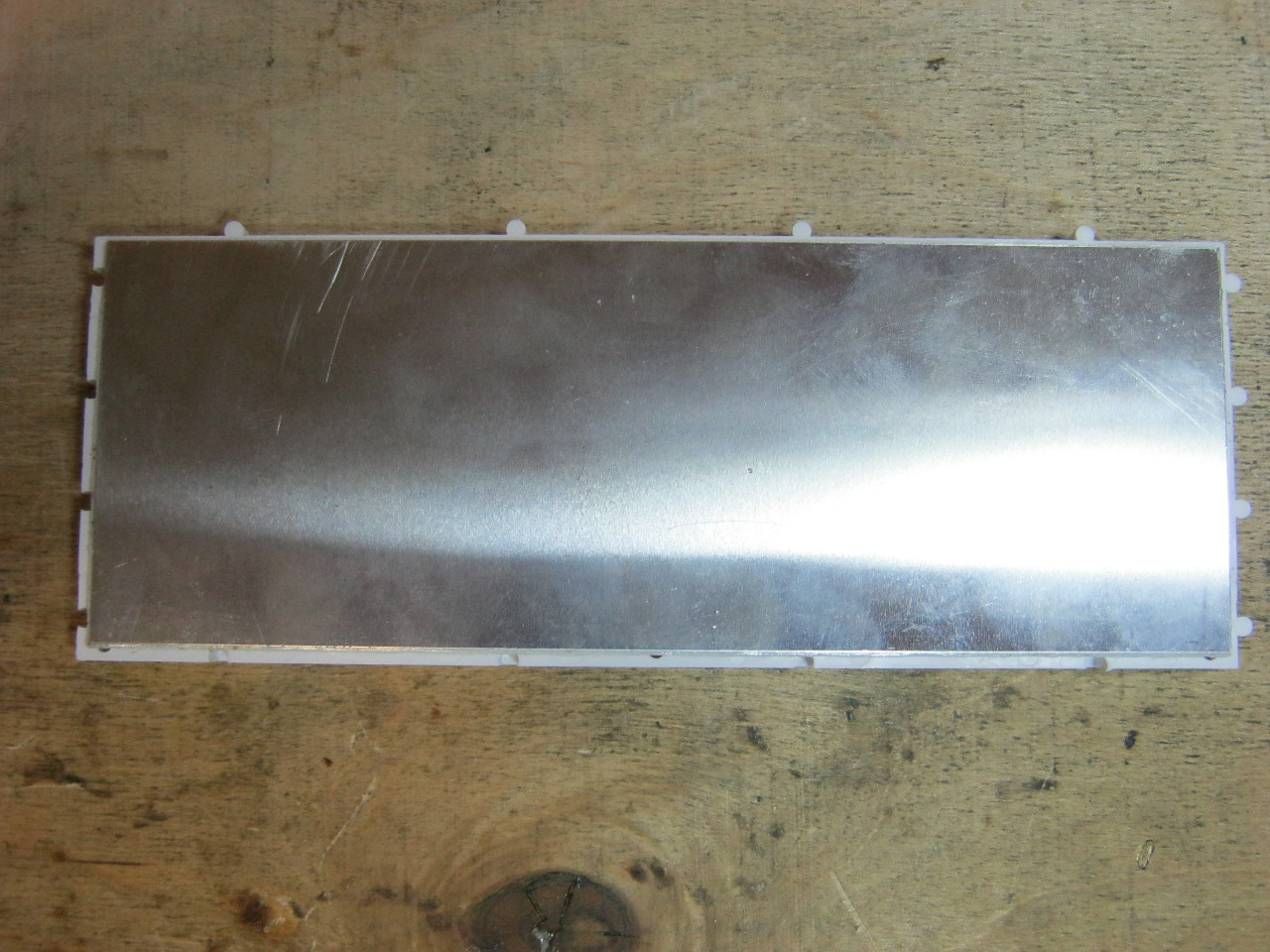
In general, I didn’t really need a breadboard (hereinafter referred to as a breadboard), since I do not manufacture electronics professionally and exclusively for myself. But when I saw it on sale by chance, I decided to order it. The board was ordered in November last year, it arrived in a simple package without bubbles, in about a month. There was nothing inside except the board itself. There was no damage given the fragility of the getinax.
It looks like this: 

The color of copper foil is pleasant, almost natural. The breadboard tracks are coated with a protective compound resembling a weak solution of rosin in alcohol. By at least When soldering, the amount of smoke is minimal and no traces of burnt rosin are observed.
The dimensions are stated to be 9x15 cm, in fact they are, the thickness is 1 mm, which in my opinion is not enough considering the properties of the material. The foil layer has a thickness of approximately 20 microns. 
last date of verification =)

My micrometer has not been checked for 31 years, so the readings are conditional. In production, the minimum foil thickness is 18 microns, which corresponds to the cheapest option.
There are 30 rows of 48 holes on the board, which ultimately gives 1440. The latter are squeezed out during the formation of the board. Drilling such a number of holes is not economically feasible. Hole diameter 1 mm. Unfortunately, parts with pins of 0.7 and 0.8 mm have to be fixed during soldering, otherwise they tend to fall out.

Octagon-shaped contact pads size 2 mm. There is no metallization in the holes. Since the life of the board is minimal and the price with metallization will be unreasonably high.

Getinax breadboard base
Getinax is an electrically insulating layered pressed material having a paper base impregnated with phenolic or epoxy resin.
Mainly used as a base for blanks printed circuit boards. The material has low mechanical strength, is easy to process and has a relatively low cost. Widely used for low-voltage circuit board manufacturing household equipment, since in a heated state it can be stamped, resulting in a board of any shape along with all the holes.
I immediately remember boards from TVs. Due to their low resistance to mechanical and thermal loads, boards based on getinax are less maintainable and in some cases have even been sources of fire...
Trial application:
These are the ingredients I use
For soldering 
Solder with rosin inside, natural rosin, soldering iron 25 W, tip temperature approximately 330-350 degrees without adjustment.
And for cutting, a defort engraver + a set of Chinese cutters 

The cutters are of course terrible in terms of quality, I bought them at New Year at JD, couldn't resist.
There was a reason to assemble a power supply for a +5V +12V-12V signal generator. At first I wanted to remake the mobile phone charger by home-winding the windings, but I couldn’t find one with a normal gap for the wires. Therefore, the choice fell on the breadboard.
A transformer of an unknown type played a cruel joke on me - since the pitch of the holes on the board is 2.54 mm - inch, I had to re-drill the holes in place. The board is drilled easily, and even a blunt drill does not particularly slow down the drilling process, although it knocks out pieces of the board from the back side.
Several photos of the finished power supply. This is exactly the case when I decided not to make the board.


The 7912 stabilizer played a cruel joke on me - the pinout does not match the 7812. Because of this, I burned diode bridge kts407. Having realized my mistake, I re-soldered. One fell off when resoldering. contact pad. So the quality of the board is to mock it up a couple of times and switch to a new one.
The contact pads were tinned with virtually no rosin, just the amount that was in the solder.

No matter how much I tried, I couldn’t make a drop on the contact; the solder always trails behind the soldering iron. Perhaps the temperature is not enough.
I'm trying to cut it off


It seems that the speed is high, but the getinax crumbles. However, the dust is not as harmful as that of fiberglass.
Why did I buy this particular breadboard and not more advanced ones - for rare use and I wouldn’t mind throwing it away. I practically don’t use metallization. A solderless breadboard was also purchased, but is currently unused. Compared to the one under review, it has a disadvantage - it requires leads of the required length and molded ones. And since I have huge stocks of old and used parts (I scold myself to constantly throw everything away), soldering is the only correct option.
Conclusions: budget layout. If you don't have a couple in stock, you can have them.
Where is the cat?
I'm planning to buy +13 Add to favorites I liked the review +24 +39To design and debug prototypes of the most various devices Arduino uses breadboards (another name is solderless circuit boards and breadboards). They come in several varieties and differ in size and some other design features. Breadboard breadboard boards can help both novice engineers in creating simple circuits and in prototyping complex devices. This article will tell you what a development board is and how to use this device.
Rarely is it real Arduino project contains less than 5-10 elements connected to each other. Even in a simple, well-known beacon circuit, 2 elements are used, an LED and a resistor, which must somehow be connected to each other. And this is where the question arises of how to do this.
At the moment, there are the following main installation methods that are used in electronics and robotics at the prototyping stage:
- Soldering. To do this, use special boards with holes into which parts are inserted and connected to each other by soldering (using a soldering iron) and jumpers.
- Cheat. Using this technology, the contact connections of devices are combined with development board by winding a clean wire to the pin contact.
The most modern option for creating prototypes is a solderless breadboard, which has undoubted advantages:
- Ability to carry out debugging work a large number of once changing the modification of circuits and methods of connecting devices;
- The ability to connect several boards into one large one, which allows you to work with more complex and large projects;
- Simplicity and speed of prototyping;
- Durability and reliability.
The English version of the name of a solderless breadboard is breadboard.
Development board diagram
To know how to use a development board, you need to understand the principle of its design.
The solderless development board has a plastic base with many holes (the standard distance between them is 2.54 mm). Inside the structure are rows of metal plates. Each plate has clips that are hidden in the plastic part of the unit.

The wires are inserted into these clips. When a conductor is connected to one of the individual holes, the contact is simultaneously connected to all other contacts of the separate row.
It is worth noting that one rail contains 5 clips. This is the general standard for all solderless boards. That is, up to five elements can be connected to each rail, and they will be interconnected.
It should be noted that although there are ten holes in each row, they are still divided into two isolated parts, five in each. Between them there is a rail without pins. This design is necessary to isolate the plates from each other, and allows you to simply connect chips made in DIP packages.

Some development boards also include two power lines on each side. Typically, the “red line” is used to supply “+” voltage, the “blue” line for “-”. Due to the presence of two power rails, two different voltage levels can be supplied to the board.
To make it easier to navigate, the breadboard also contains numerical and alphabetic symbols that can be used as a guide when creating, for example, wiring instructions.
Main types of development boards
Development boards differ in the number of pins located on the panel, the number of buses and configuration. There are also breadboards in which contact connections are made by soldering, but working with them is more difficult than with solderless devices.
Depending on the characteristics, the most common types are:
- For assembling large chips, solderless boards with 830 or 400 holes are mainly used. For connecting several components and supplying wires to the necessary points - 8, 10, 16 holes;
- With the presence of grooves for adhesion of boards, which allow the implementation of fairly large projects;
- With self-adhesive on the base for secure fastening to the device;
- With symbols printed on the board for connecting devices.
Depending on the cost and manufacturer, the package may include additional accessories– jumper wires, various connectors. But the main quality criterion always remains the number of contact connectors and their technical characteristics.
How to use a development board
Using the breadboard is quite simple. When creating a circuit, insert into the holes on the plastic case necessary elements– capacitors, resistors, various indicators, LEDs, etc. The width of the connectors allows you to connect conductors with a cross-section from 0.4 to 0.7 mm to the contacts.
The simplest example of creating a circuit prototype using a breadboard would be the following implementation:

To assemble it you need to take:
- Breadboard;
- wires for connection;
- 1 LED;
- tact button;
- resistor with a nominal resistance of 330 Ohms;
- 9V Krona battery.
The plus of the battery is connected to the positive bus, and the minus to the negative. If the circuit is assembled correctly, then when you press the button the LED will light up.
Attention! Solderless breadboards are absolutely unacceptable to use with a voltage of 220V!
Breadboard breadboards are optimal for creating almost any digital circuits and are not intended for assembling analog circuits, with high sensitivity to the resistance value. In their practice, they are often used by both beginners who understand the basics of circuitry and experienced professionals due to the ease of installation and High Quality connections of working contacts.
All people in the world, young and old, know that before you create anything, you must first create a model of this “something,” be it a model of a building, a stadium, or even a small rural toilet. In electrical engineering this is called a prototype. A prototype is a working model of a device. Therefore, experienced electronics engineers, before assembling a device according to a circuit on the Internet, posted by no one knows who and no one understands why, must make sure that this circuit will actually work. Therefore, the circuit needs to be quickly assembled and made sure it works, that is, assembled layout. Well, in order to assemble it, that’s exactly what we need bread board.
Types of development boards
Thick cardboard
A long time ago, when you were not even in the plans, our grandfathers, and maybe grandmothers, you never know :-), used thick cardboard. This is the fastest and cheap way checking circuits. Holes were cut in the cardboard for the terminals of the radio elements and on the other side they were connected using wires and other elements if they did not fit on the front side. It looked something like this:
A is the front side, B is the back side.
Everything would be fine, but I had to solder the leads, make sure that nothing short-circuited anywhere, and while you are “sculpting” this circuit, you can even inadvertently get confused :-). Yes, and somehow it’s not beautiful.
Homemade breadboards
I still found these times at the radio circle. Back then we made breadboards ourselves. We took a sharp cutter and cut squares on foil PCB. Next, they were coated with solder.

If we needed to connect tracks somewhere, we simply made jumpers between the squares with a drop of solder. It turned out high quality and beautiful. If you were too lazy to solder the radio elements onto a normally wired board with tracks, you simply left it as is and used the device.
Disposable development boards
Manufacturers have finally given up on this matter, or as they say in economics, demand creates supply. Ready-made mock-up scarves, single-sided and even double-sided, began to appear for every size and taste.


By the way, you can find them on Ali right away a whole set .
The holes are very conveniently matched to the sizes of the pins of the microcircuits, as well as other radio elements. Therefore, it is very convenient to assemble and test electronic devices on such breadboards. Yes, and they are inexpensive.

back side Such development boards with ready-made devices will look something like this:

What are the disadvantages of these development boards? It is still better to use them once, since with repeated use their spots may fly off, which will lead to its unsuitability.
Solderless breadboards
Progress is moving with its confident steps across our world, and now they have appeared on the market solderless breadboards.

They cost a little more than simple disposable breadboards, but honestly, it's worth it.
They are very convenient in terms of installing parts, as well as their connection with each other. Wires no larger than 0.7 mm and no less than 0.4 mm in diameter can be inserted into such breadboards. To find out which holes and tracks communicate with each other, we check the whole thing. To design large circuits (suddenly you will develop some kind of control unit for a hadron collider), you can add the same breadboards end-to-end. There are special ears for this. One move, and the breadboard will become a little larger.

Well, what kind of breadboard can there be without connecting wires? Connecting wires or jumpers ( from English- jump), are needed to connect radio components on the breadboard itself.

A little later I bought these jumpers from Aliexpress. They are much more convenient than wire ones:
.JPG)
Everything is simple here, take the jumper and insert it with a slight movement of the hand


Let's put together a simple circuit for turning on an LED via a button on a breadboard

This is what she will look like

Set the Power Supply to 5 Volts and press the button. The LED lights up bright green. This means that the scheme is workable, and we can use it at our discretion.

Conclusion
Solderless breadboards are taking the world by storm. Any circuit on them can be assembled and disassembled in a matter of minutes. After assembling and checking the circuit on the breadboard, you can safely begin assembling it in its pure form. I think every self-respecting electronics engineer should have such a breadboard. But keep in mind, schemes with high current in a circuit, it’s better not to check it, since the contacts of the breadboards can simply burn out - Joule-Lenz law. Good luck in the development and construction of radio-electronic devices!
Where to buy a development board
A development board with flexible jumpers and even ready-made block 5 Volt power supply can be immediately purchased as a set on Aliexpress. Choose to your taste and color!

If you don’t want to, then the easiest way would be to buy a disposable breadboard and assemble a finished device on it: