Motherboard repair. Replacing capacitors
In this article, friends, we will try to answer the question of how to replace capacitors on a computer and in what cases should this be done?
In general, resoldering capacitors on a board is not a difficult process. You just need to have a minimum set to ensure high-quality soldering and subsequent cleaning printed circuit board from her tracks. We will definitely talk about this too!
I recently set my personal record for replacing large number capacitors on the board at a time. I re-soldered 10 (ten) at once and the motherboard is now working stably in one of the departments of our organization.
Here it is (those capacitors that were replaced with serviceable ones are highlighted in red). The photo below is clickable:
It's a pity that I didn't take a photo of this motherboard BEFORE I replaced the capacitors on it. To be honest, I didn’t initially intend to write an article on this topic, but then I received several letters in a row from our readers with a proposal to cover this topic in more detail.
By that time, I had already soldered all the capacitors from the board and it was lying on my desk, waiting for the appropriate number of elements needed to be replaced.
Note: we talked about how to correctly select capacitors to replace faulty ones (swollen and leaking) in one of our websites.
So, after replacing ten capacitors of different ratings and capacities, our motherboard successfully passed testing (multiple switching on and off and subsequent stable operation throughout the entire working day):

As you can see, I also use the photo above for testing, which shows all the stages of passing the initial self-test of the system after turning it on.
Note: with some experience (and developed intuition) :) using the codes issued by the board, you can find your bearings as to whether the re-soldering of the capacitors was successful and whether everything was done well?
What I mean? Let me explain using the example of one of the first boards on which I replaced swollen electrolytic capacitors. Then I did not have the necessary soldering supplies and I decided this: I will solder without everything that is required, but - carefully! If it works, great, if not, no big loss :)
At that time, I only had a soldering iron with a thin 40-watt tip and a coil of thick solder. I didn’t even have rosin on hand!
This is the kind of soldering iron I used back then:

Note: in order to replace capacitors on the board, choose a soldering iron with a power of 40 to 80 watts. No more is needed, otherwise there is a risk of overheating (melting) and damaging elements located close to the soldering area on the system board. Also, the thinner the tip of the tool, the easier it will be for you to work with it.
Let's continue, before the procedure I placed in one of the free PCI connectors your computer POST card(PC Analyzer), turned on the motherboard, closing the corresponding contacts on it, and recorded the code number after which the system stopped booting. Those. The fans are spinning, but nothing else is happening. BUT - we remember the error code that the download is stuck on, and this is very important!
After this, I free the board from all the “extra” (that will interfere with me when soldering), remove it from and replace the capacitors (we will discuss the process itself in more detail below). I re-soldered several capacitors near , placed the board on a wooden surface, placed it in it, brought it to VGA cable from the monitor, connected it, returned the POST card and launched it.
After that, I began to look at the boot codes, waiting for the one at which the computer boot stopped. So it appeared on the seven-segment display, lingered a little and... disappeared, replaced by the next one (I mentally immediately congratulated myself on the first successful replacement of capacitors), BUT!... Unexpectedly new code was replaced by one I had already seen before (faulty) and the motherboard began to issue sound signals about the error. Repeated reboots just secured this algorithm: the faulty code stays on the display a little longer than usual, is replaced by the next one and immediately returns.
In connection with these observations, I made the first conclusion: replacing capacitors on the board should be done not only carefully, but also with all the necessary tools. What I've done? I went to the nearest radio equipment store, bought everything I needed there and again thoroughly soldered (warmed up) everything contact pads(legs) of the capacitors I soldered, after which I thoroughly cleaned the soldering areas with a special liquid. As a result of the manipulations performed, motherboard successfully “started up” and, I hope, still works to this day :)
Now I use an improved version of a soldering iron with a manual tip heating temperature controller (photo - clickable):

It says on the box that this is without a hot air gun (a hair dryer that can use hot air to desolder entire microcircuits from printed circuit boards).
This “pleasure” is inexpensive, and working with it is much more convenient than with a regular soldering iron. I set the desired temperature using the regulator and the soldering iron constantly maintains it (without burning out or overheating the tracks and other elements on the printed circuit board). In addition, the tip is covered with a special protective material, which significantly extends its service life under heating conditions. Also included is a removable holder for a soldering iron - very convenient :)
Now let's move on to related accessories for soldering capacitors (and not only them) and consider them in more detail. I have placed all the “bells and whistles” that I myself use in the photo below:

Let's look at each element separately:
- braid for removing excess solder from the soldering area (it comes in different thicknesses, pay attention to this when choosing!)
- tubular solder with liquid flux inside
- soft solder in coil
- Cleaning liquid for washing joints from residual dirt and flux
- regular rosin
If you do not plan to install components once a month, then such a thing as a stand for a soldering iron will be very useful. It looks like this:

Advice: pay attention to the fact that the base of the stand is massive (heavy). Otherwise, there is a chance that it will simply tip over under the weight of the soldering iron and electrical cable!
To remove excess solder, I sometimes use a manual desoldering pump:

A good alternative to this suction could be its improved version, equipped with a heater.

Note: It can be called differently by people: thermal pump, soldering iron with desoldering pump, piston desoldering pump with heater, etc. Therefore, when purchasing, keep this in mind (you can puzzle the seller out of the blue) :)
Sometimes it is an irreplaceable thing when you need to unsolder a microcircuit with a large number of pins located on the back side of the board or solder some kind of connector from it. With some practice, quite handy tool, expanding our capabilities and making the work of the “soldering man” easier.
Perhaps the main nuance in the work is that the tip of the tool may be thicker than necessary for some types of work: the same capacitor leads or other “small things” on the board. Since we need to ensure tight contact of the tin pump tip with the surface being processed, it would be logical to tilt it at an angle (for good contact with the solder), as shown in the photo below:

When we feel (see) that the tin has “floated,” we press the button, the piston will straighten and draw in the molten solder.
Periodically, the tool must be cleaned of alloy accumulated inside. As a rule, a heat pump has a removable tip (tip), which can be unscrewed, and a collapsible handle (immediately above the heating element). It also curls counterclockwise.
Remove all remnants of solder, check the working barrel of the tool for clearance. If there are any comments, clean it with a thin knitting needle or wire of the appropriate diameter. When disassembled it looks like this:

I’ll say right away that the most expensive of all the above is a desoldering pump with a heater - $6, the rest costs even less. Naturally, the soldering iron itself costs 7-8 dollars, and the soldering station shown in this article costs 20. As you can see, such a soldering kit is available to everyone!
So, as usual, let's look at each of the points listed above separately.
The desoldering braid perfectly absorbs heated tin, acting like a sponge. We simply press it to the place of soldering with a heated soldering iron and when the solder is absorbed, remove it, and cut off its used end with scissors.

The braid is sold in a small reel of 1.5 meters, it costs a penny, and the benefits from it are “a whole car!” :)
I like to use tubular solder to replace capacitors (compared to ordinary rosin) for the reason that it already contains flux inside, which, when heated, immediately spreads over the soldering site.
Note: The term “flux” refers to a substance designed to remove oxidation and carbon deposits from a soldering surface. With it, the surfaces to be soldered better “grab” each other. Also, its use helps to improve the spreading of molten solder and its subsequent protection from the effects of the environment. There are many types of fluxes: in the form of liquid, gel, paste or powder, again - the familiar rosin. There are also solder pastes that contain small particles of solder along with flux. There are also no-clean (do not require subsequent cleaning or rinsing) and regular ones.
I use this liquid variety - “LTI-120”. This is one of the varieties of alcohol-rosin fluxes (SKF-flux - liquid rosin + alcohol). It has a brush inside the cap, so applying it to the soldering area is very convenient:

In short, soldering flux is like butter for porridge: you can eat it without it, but somehow you don’t want to :)
But I use the thicker solder in the coil for everything else, except for resoldering capacitors on motherboards. When soldering wires, it lays down in an even thick layer, which gives the connection additional strength and reliability.
I recommend using a cleaner (or its equivalent) to remove traces of work from the board. How do I do it? I drip it onto the soldering areas and thoroughly wipe them with a stiff toothbrush specially designed for this purpose. We brush with a brush without hesitation, it won’t do anything to the board or capacitors :) You can also moisten a cloth with acetone or medical alcohol and wipe the board (this is a matter of habit).
Separately, to be honest, I don’t use rosin very often. Rather, I need it to clean the hot tip of the soldering iron, which can “pick up” various unnecessary particles while working. I dip it thoroughly in rosin, then carefully wipe it on a cotton cloth folded in several layers. Also in use by “soldering people” there are special tip cleaners. This is, as a rule, brass or copper shavings into which a hot tip is inserted to remove carbon deposits and solder particles from it.

In principle, nothing prevents us from buying an ordinary steel sponge for washing dishes (you know, the kind with a spiral) and, with the same success, using it to clean the tip :)
Now let's take a closer look at how to properly use a manual desoldering pump when replacing capacitors on the motherboard? The principle of its operation is simple (like a syringe), only the latter’s task is to push out liquid, and the destin pump draws it into itself. We simply squeeze its spring until it locks in the lower position, bring it close to the soldering site and, by pressing the spring release button, force the semi-liquid solder to be drawn into the hole.
So, we warm up the tin well near one of the “legs” of the capacitor and (until the solder hardens again) cover it on top with a suction and press the button:

After completing the work of replacing capacitors, it is imperative to disassemble the tool (it unwinds like ball pen) and remove any remaining solder that has been sucked inside.
Here's what, in my case, the solder joints looked like after treating them with braid and a desoldering pump and washing them with a cleaner:

And here is an example of sloppy soldering on a board:

Here's a close-up:

Such soldering may, over time, lead to a short circuit on the board or to the formation of various oxides on it, which will also most likely lead to its damage.
Resoldering and replacing capacitors on the board
I don’t see any point in describing in detail how to solder capacitors (I mean the process itself). Because here you need to gain a little experience, and you can only do this by trying it yourself. Here are a few useful tips give it - with pleasure! :)
Start with the procedure desoldering capacitors from a non-working board. The more you solder, the better. On at this stage Our task is to get a feel for working with a soldering iron, to understand when and how solder melts, and how quickly it hardens back? To fill your hand, in one word.
When removing the capacitor from the board (when you heat the tin near its leg), shake it from side to side and sooner or later you will see that the “leg” “falls” through the molten solder into the hole. Do the same with the other one. If necessary, reheat the board from above and remove the element completely.
After you have it in your hands, align its contacts with tweezers (if they are bent), remove any remaining solder from them with a soldering iron (if there is any there) and use a regular office knife to clean them well (scrape them), thereby ensuring a good future electrical contact. All! The capacitor is soldered and ready to be transplanted! :)
Advice: Previously, boards using lead-containing solder were in use, but now more and more people are switching to lead-free. And the melting point of lead-free solder is 20-30 degrees higher (220 degrees Celsius versus 190). Thus, the soldering area needs to be heated longer or stronger, which can lead to additional problems. Therefore, there is such a method: before soldering, we apply tin (apply on top using a heated soldering iron) to the terminals of the capacitor fusible solder (tubular with flux inside). You can also use low-melting alloys “Wood” or “Rose” specially developed for this purpose. Thus, we, as it were, mix both types of solder. As a result, we obtain a lower final melting temperature at the soldering site.
Before replacing the capacitors on the motherboard that you want to revive, we will also need to remove failed (swollen or leaking) elements from it. Here, be very careful (especially for the first time) and do not damage the conductive paths with which the surface of the board is densely dotted with a hot soldering iron. Some of the capacitors may be located very close to them.
Note: before soldering (especially used capacitors) into the board, use a multimeter or ESR tester. Who knows?
After you prepare the board in this way, I recommend that you do one more thing: take a needle from a disposable syringe, cut it in half using side cutters (if necessary, remove the resulting edges with a file) and, having warmed up the place of future soldering from above, insert it into it from below needle point:

We have just cleaned the mounting hole so that the capacitor leg can be placed in it smoothly and comfortably. Do the same procedure for the second pin, insert the legs of the capacitor into them on the other side, press it firmly to the board and start soldering.
Advice: to remove excess solder from the "nickels" it is better and safer for the printed circuit board to use copper braiding of a suitable thickness (2-3 mm). We apply flux, press the braid with a heated soldering iron and begin to carefully move it along the surface to be treated. A sufficient amount of flux should ensure this slip. The same procedure can be done on the opposite side of the board. After this, the mounting holes should be clean. Personally, I find it very convenient to use Chinese flux gel " Amtech RMA-223».
Let me remind you that after finishing soldering, do not forget to clean the board with a special liquid (ideally isopropyl alcohol). You can also use ethyl medical grade (95 percent), but it leaves a nasty white coating that visually spoils the final picture! Droplets of splashed solder may remain on the board, invisible to the eye, which can easily short-circuit tracks located close to each other. A - an unpleasant thing! And the active flux (if it was used) may, over time, enter into some complex reaction with the surrounding components, but do you need it? :) Therefore, rinsing off is a must!

The photo above shows a wash based on isopropyl alcohol (left) mixed with “Galosha” gasoline (sometimes called “galosha”) purified from oil impurities and regular ethyl (pharmacy grade). True, the jar says 70%, but it’s better to find 95%. We need to be more assertive! :)
Towards the end, I wanted to show you a couple more accessories that make soldering easier. They are essentially similar, but there are some differences. So, this, of course, is the so-called “third hand” of the soldering machine. Don't be afraid, we are not talking about any natural mutations here, it's just a device that holds a board or tubular solder at the moment when we work :)

In the "alligator clips" we place small fee(or what we need to hold during soldering), to make the work easier, we position the whole thing under magnifying glass and we work calmly. The design is convenient in that it has many degrees of freedom (it bends in all possible directions and at any angles). This is its cheapest option (costs 4-5 dollars), more “sophisticated” ones can be equipped with a holder for a soldering iron, LED backlight and a double magnifying lens.
You can also use something like a binocular magnifier (for example MG81007) with LED backlight. Gorgeous thing! Your hands are completely free while working, there is no need for additional illumination, three magnifying lenses that can be used individually or all together. In short, I highly recommend it :)

Another “device”, which is also intended for fixing objects during operation, is a clamp (mounting table or PCB holder). Their special modifications (for small printed circuit boards) are produced by various companies involved in equipment, accessories and consumables for soldering. For example, this is what a clamp from the Baku company looks like.

There is a guide, there is a spring on it. We simply move the latch in the direction indicated by the arrow, it compresses the spring, we install our board into the resulting gap, release the latch and it fixes (springs) it. Very comfortably!
There are ordinary (metal) clamps that are sold in any hardware store. You can use them too. They are usually attached directly to the table:

That’s basically all I wanted to tell you about replacing capacitors on the board and other accessories for the soldering process. At the end of the article, I would like to give a few more photographs that I took at our work, and remind you that if the capacitors have lost their capacity, any device can begin to behave “inappropriately”. (only the fans work) or reboots spontaneously, unstable operation of other devices is also possible.
For example, in the photo below we see, on which there are also electrolytic capacitors and one of them is swollen:

Here's a close-up photo:

As you understand, guarantee stable work no one can use devices in such a situation. On the other hand, there are times when a motherboard works without failures even with five or six swollen capacitors. Question: for how long and will something else fail because of this?
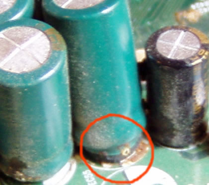
And here is one that was disassembled in our department with the same problem:

Here - close-up problem area:

As you can see, faulty capacitors can be located anywhere. Keep this point in mind when diagnosing any problem. are also quite often caused by this problem and the replacement of capacitors here occurs according to the same principle described above.
The motherboard is a very complex electronic device that combines and coordinates the operation of all computer components. Over time, the motherboard may fail for various reasons: overheating, aging components, etc.
Very often on old motherboards you can find swollen electrolytic capacitors. They look like barrels with a swollen top or bottom. In this case, there may be traces of leaked electrolyte near the capacitor. Such a motherboard, in principle, can work successfully, but most often a computer with such motherboard won't start.
To bring the motherboard back to (feelings), you should replace the swollen capacitors with new ones. You can do such repairs yourself without the help of a service center. However, if you have never held a soldering iron in your hands and do not have the slightest idea how to work with it, then it is better to contact them in order to avoid aggravating the situation and completely (killing) the system motherboard.

To replace capacitors, you will need a low-power soldering iron (up to 40W) with a narrow tip or a soldering station (ideally), rosin or soldering acid (preferred), tin solder, alcohol or purified gasoline.

Before you begin to solder the capacitor, carefully inspect the motherboard, find any capacitors that are swollen or have traces of leaked electrolyte. Electrolytic capacitors are soldered with respect to polarity. Their housing is usually marked with a negative (-) terminal designation. On the motherboard itself, when you remove the capacitor, there is also a polarity marking. In order not to confuse the polarity, you can photograph the location of the capacitors.

And a few more words about preparatory work. The motherboard is sensitive to static voltage, so it would be advisable to ground the soldering iron and the motherboard. For the same reason, you cannot work in synthetic clothing without observing additional measures protection. Use antistatic gloves and wrist straps.
Desoldering the capacitor requires special care, since the printed circuit board has a multi-layer assembly. This means that the tracks not only go on both sides of the board, but also inside it! If you use a soldering iron, heat the legs of the capacitor one at a time and carefully remove it from the printed circuit board. After this, the holes in the board should be cleaned of any remaining solder. You can use a toothpick, which should be inserted into each hole one by one and heat the board on the other side with a soldering iron. This way, any remaining tin will be removed. If you use a soldering iron with tin suction, then cleaning the board from solder residues will not be necessary.

When the capacitors are soldered, you need to check their rating and operating voltage in order to purchase new ones to replace them. The capacitance of the capacitor is indicated in microfarads (µF, uF), and the voltage in volts (V, V). If a soldered capacitor, for example, is marked 6.3V 2000uF, then its operating voltage is 6.3 V and the capacitance is 2000uF. When purchasing a new capacitor, you may not find exactly the same capacity and operating voltage. It is allowed to install capacitors with a higher operating voltage (12V instead of 6.3V) and a larger capacity (2200 µF instead of 2000 µF). It is highly not recommended to use capacitors with lower voltages, since such a capacitor will fail very quickly.
Also, when choosing a capacitor, you should Special attention Pay attention to its size, since the motherboard has a tight installation, and the components are often installed almost end-to-end, then installing a larger diameter capacitor may not be possible. With capacitors that are large in height, there are usually no installation problems.
Now all that remains is to carefully solder the new capacitor and check the functionality of the motherboard. Install the capacitor into the motherboard, being sure to observe the polarity, and solder its legs to the back of the printed circuit board. Do not use a large amount of solder to prevent it from spreading and shorting adjacent contacts. When soldering, avoid excessive heating of the board, as this can lead to desoldering of adjacent elements. Once everything is soldered, remove any remaining soldering acid or rosin from the PCB using alcohol or refined gasoline.
A capacitor is a charge storage device, one of the most common parts in modern electronic devices. Their other name is containers. Mostly on the motherboard, these radio components are used in the supply voltage filter circuits of various computer components. Capacities are one of the most important components of power supply circuits, since the stability of supply voltages is the key to long and trouble-free operation of the entire PC as a whole.
Attention! Failure of capacitors poses a great danger to everything electronic device in general, it doesn’t matter whether it’s a computer or a simple iron. Any breakdown of the power supply circuit is fraught with breakdown of almost all the electronic “stuffing” of a particular device.
A capacitor has two main characteristics - capacitance, measured in farads, and voltage, measured in volts.
There is only one reason for swelling (deformation) of the capacitor shell - overheating. But there may be several reasons for overheating. Moreover, they can be both internal (manufacturing quality of the element itself, quality of the rectified voltage, load size, etc.) and external, for example, heat in the space around the element.
Let's look at the main reasons why capacitors on the motherboard swell:
- various types of external overheating;
- aging of the element itself;
- exceeding the rated current and voltage values (the main reason);
- voltage polarity change;
- mechanical damage;
- manufacturing defect.
Just 30 years ago, containers did not swell due to the above reasons, but actually exploded. But, modern designs make it possible to avoid this unpleasant phenomenon, thanks to the special design of the lid, which can be slightly deformed and create an external “bloating” effect. It is the appearance of such a cover that indicates that the functionality of the element is impaired and it requires replacement.
Direct signs of a malfunction - a decrease in its capacity and a change in impedance - can only be detected by measuring its parameters, which in most cases to the average user impossible to do. We can say with confidence that the above performance characteristics swollen capacitor significantly different from what they should be.
However, to visually check the functionality of all capacitors, do not constantly open the cover system unit and look inside. There are many indirect reasons to tell if something bad has happened to the elements.
The main indirect sign of the presence of inoperative elements is the complete inoperability of the PC, or the instability of its operation. Typically, this appears in critical modes, when in one PC node (or in several) there is a significant increase in performance, and as a result, an increase in power consumption. In this case, the computer freezes, slows down, and in some cases reboots.

How to replace a swollen capacitor
Let's look at what needs to be done if the capacitor on the motherboard is swollen. Actually, there are only two ways to solve the problem: take the PC to service center or try to fix the problem yourself.
Important! The problem will have to be solved in any case. Even if the system is working stably, bloating is just the beginning. Very soon the capacitor may fail completely. And, if it is involved in the power supply circuit important device(for example, a microprocessor), this may lead to failure of the latter.
If you decide to make the replacement yourself, then for this purpose you will need the following tools:
- low power soldering iron (up to 30 W);
- vacuum solder suction;
- wire cutters;
- solder (preferably lead-free);
- any soldering flux (in the form of paste, gel, alcohol solution of rosin, etc.);
- cotton wool and alcohol to remove flux residues.
Naturally, new replacement parts will also be needed.
Attention! The capacity rating of the elements must fully correspond to the value written on the parts being replaced! It is allowed to use elements with higher voltage, but the capacity must be exactly the same.
The sequence of actions is as follows:
- the legs of the element are coated with flux and heated one by one with a soldering iron;
- as soon as the solder on the motherboard on both legs melts, you should carefully remove the part from it;
- the holes should be cleaned using solder suction;
- Next you need to, observing the polarity, insert it into the motherboard new element, and cut off the legs with pliers so that they protrude no more than 1-2 mm;
- coat the legs and landing pads with flux and seal the new element;
- Wash the area around the soldering area using cotton wool and alcohol.
How to avoid capacitor swelling
The main thing is to prevent these elements from overheating. Why you should follow simple but effective rules:
- There must be sufficient ventilation in the case in which the PC is located. It is not recommended to exceed the temperature inside the housing above +45°C.
- The power supply must have a power reserve of at least 10-15% of that consumed by the PC at its peak performance. This will help avoid large current loads and significantly reduce the heating of all elements in the power circuits.
- When assembling a PC and connecting its components to each other, you should carefully monitor the correct connection and polarity of certain elements.
- To not allow mechanical damage capacitors.
- Do not operate the PC 24/7. For this purpose, there are completely different devices - servers. Server components have much better performance characteristics and are designed for round-the-clock operation.
You can also look at articles on topics and.
Now we have come to the problems of the computer motherboard. IMPORTANT! Unlike all other component failures, in in this case We don’t have a single program in our arsenal that could clearly “tell” that we have a motherboard problem.
Among the tools at our disposal are: common sense, observation, the ability to reason logically and - experience that comes with time :) Therefore, before throwing it into a landfill, completely working device, make sure to at least do everything that will be described in subsequent articles covering motherboard problems.
So, let's get started :) Very often the cause of these problems is capacitors that have lost capacity or are "swollen".
Symptoms of various “glitches” associated with failed capacitors on the board can be different. In the worst case, the computer simply will not turn on. More precisely, except for the rotation of all available fans, it will not show any signs of “life”. Also, the PC may not turn on the first time or after a certain number attempts (when the capacitors are warm enough).
If the problems on the motherboard are serious enough, the computer may spontaneously reboot (due to various components receiving low voltage as a result of capacitors that have lost their capacity). All sorts of “freezes” of the operating system are possible.
To be fair, it is worth noting that sometimes there are instances of motherboards on which there is a whole series of swollen elements and these boards continue to work stably. In this case, perhaps you need to follow the golden rule of a real administrator: " Works? - Do not touch!" :)
If you still encounter the symptoms described above, then read on.
Swollen capacitors on the motherboard look like this:
Motherboard problems may be caused by them. For greater clarity, let's look at another photo below.

On the left we see a normal capacitor, and on the right a “swollen” one. It is these unstable elements that often cause problems with the motherboard. They can be easily detected by carefully inspecting the board. When palpated (to the touch):) such a capacitor will have a slight swelling on top, while the worker will feel a small depression in the same place.
Capacitors serve to smooth out electrical voltage in the computer power buses. They charge and, if necessary, discharge, releasing part of the accumulated charge. The task of capacitors located in power supply circuits (or among other phase elements) is to absorb excessive voltage surges and replenish it during a “drawdown” from the previously accumulated charge.
They are filled with liquid electrolyte. At unstable work element, the electrolyte may simply “boil” and leak out of the capacitor shell.

In the most “clinical” cases, the protective shell simply “explodes”, splashing out the electrolyte.

In case of such problems with the motherboard, you must carefully carry out visual inspection for the presence of swollen “leaking” capacitors not only on top, but also in places of contact directly with the board. There are cases when electrolyte leaks from the bottom of the cell, which can also lead to problems with the motherboard.
In such cases, as a rule, it is carried out using known good ones of similar (or larger) capacity. Replacement implies a banal resoldering of them :)
Note: The capacitance of capacitors is measured in farads. Upon careful examination, you will find its numerical designation on its body and the abbreviation - (Mkf) or (Mk).
What is the cause of all the computer motherboard problems we listed above? As a rule, this is often associated with prolonged overheating (improperly organized or completely absent outflow of hot air inside).
The average time between failures of a traditional electrolytic capacitor is 2000-5000 hours. Moreover, with an increase in ambient temperature, this time decreases sharply. Draw your own conclusions, as they say :)
Recommendations: Carry out preventative maintenance and inspect your computer more often to remove accumulated dust inside the system unit. Make sure that all fans installed inside the case are working properly? If necessary, install additional
Also, the cause of such problems on the motherboard may be poor-quality electrical power. Poor quality can eventually cause the problems described above. Remember the rule: should be in a good computer good block nutrition!
Well, of course, if you buy a motherboard from an unknown manufacturer for $30, then there is no guarantee that this is the same Chinese manufacturer I didn’t save on components (in particular, on capacitors) and didn’t solder low-quality ones with low capacity, which will fail after a few months of operation.
It would also be a good idea to know how to test capacitors using a multimeter.
Now on the market in large quantities There are motherboards on which solid capacitors are installed.

They do not have “petals” on top, characteristic of liquid ones. Their body consists of a solid homogeneous material.
Instead of a liquid electrolyte, they use a special conductive organic polymer. Average term their service life is about 50,000 hours. At the same time, they can dramatically reduce the rate of typical motherboard problems, since they themselves are much more reliable in operation and more resistant to environmental conditions.
Hardware failures can manifest themselves in different ways: computer crashes, artifacts on the screen, input/output errors when accessing the hard drive. Usually you try to solve the problem by installing new drivers, adjusting hardware parameters in the operating system, adjusting BIOS options, or, if all else fails, replacing components such as memory. But what to do if all this does not lead to the desired result?
Unfortunately, not only can it fail operating system or device drivers. And even purchasing the latest components, such as quad-core processors and terabyte hard disks, cannot prevent hardware failures. Hardware manufacturers usually determine the lifespan of each component of a computer or laptop. For hard drives This is typically five years, but other components may last longer. Key components such as processors, memory, motherboard or video card usually last significantly longer. If, of course, the operating and cooling conditions are normal. But it is impossible to predict how long this or that component will actually last.
One of the reasons for the strange behavior of a computer may be failed electrolytic capacitors, which are found on many semiconductor components, on the same motherboard or on a video card. So what should you do if a malfunctioning capacitor on the motherboard leads to a computer failure? If the warranty has not expired, you can go to the store and replace the old motherboard with a new one. You may need to buy new memory and processor. But there is a less expensive solution. If you are not afraid of soldering, you can replace the electrolytic capacitor yourself. In our article we will show how you can inexpensively revive your motherboard or video card, if you have one at hand necessary tools.
Capacitors and resistors are the most commonly used components in electrical circuits. Capacitors are in diplexers, oscillatory circuits, interference suppressors or filters. Electrolytic capacitors differ from other capacitors in that the aluminum housing contains a liquid that conducts current when voltage is applied. The liquid is called an electrolyte.
Almost all electrical diagrams Capacitors are used in power supply filters. They cope with voltage peaks that transformers or transistors cannot respond quickly to. Without going into too much detail, a capacitor works like a battery: it charges when voltage is applied. The charge in the capacitor is retained when the capacitor is disconnected from the voltage source. Such properties allow you to equalize the voltage, say, in a power supply.
Transformers allow you to reduce the voltage in the power supply to the required level. Rectifiers create D.C. from the supplied alternating current. But the current after the rectifier is not ideal; ripples are still noticeable. But short voltage drops caused by ripples can be compensated by a capacitor, which acts as a source of additional voltage, stabilizing the supplied voltage. For stabilization circuits, capacitors with lower equivalent series resistance (ESR) are used, which can effectively cope with ripple.

Leaking capacitors near the AGP slot.
Internal resistance (ESR) is usually determined by the conductivity of the electrolyte. Therefore, the electrolytes used in low-voltage capacitors internal resistance, must have very good conductivity. To increase the conductivity of the electrolyte (it consists mostly of dispersants), it is necessary to use additives. And one of these additives is water. Due to the dissociation of water, free ions are released, and therefore electrical conductivity increases.
However, insufficiently purified water interacts with the aluminum casing of the capacitor, causing corrosion. This creates gases that increase internal pressure, and the condenser begins to swell. There are special notches on the top plane of the condenser that open when the pressure is too high, allowing gas to escape. Sometimes the notches do not help, and the capacitor explodes “beautifully”. The same thing happens when too high a voltage is applied. The electrolyte that was in the capacitor may leak onto the motherboard and cause short circuit. And even a fire. In general, motherboard reliability caused some problems for manufacturers between 1999 and 2005. They often used capacitors with low-quality electrolyte, which led to numerous failures and a significant decrease in the reliability of motherboards.
But it’s not just low-quality electrolyte that can cause a capacitor to fail. Like any other liquid, an electrolyte can change its physical state and simply evaporate. And this can happen not only in a running system, but also when the system is turned off or the motherboard is generally stored separately. From good cooling computer case It's not just components like memory or processors that benefit. Good cooling It also increases the lifetime of capacitors, since the probability of evaporation depends on the ambient temperature. Lowering the temperature by 10°C doubles the life of the capacitor.

The capacitor has a total capacity of 1000 µF.
Usually a capacitor can be recognized by the effects of an explosion. Swelling or even loss of integrity indicates that the capacitor will soon fail (if it is still working). Sometimes the rubber gasket covering the capacitor from the bottom is pushed out by the gas. Capacitors whose electrolyte has evaporated and left no traces on the aluminum case are very difficult to detect. If the capacitor dries out, its capacity decreases. To measure the capacitance of a capacitor, you must use a multimeter (see illustration above). In our case, we used the Digitek DS-568F, which is quite suitable for our purposes, and it costs less than $40.

We tried to find a motherboard with failed capacitors - and found it. An old motherboard from MSI was gathering dust in our warehouse for a long time. However, defective capacitors are a problem for almost any manufacturer. That's why this product chosen as an example.
The K7Master board has two processor socket, so she is quite worthy of resuscitation. If you have to change this motherboard, you will have to change both the processors and the memory (in this case, registered DDR is used). And this is not very pleasant.
We didn't know if all the capacitors had failed. But since the capacitors are the same, we assumed that they all needed to be replaced. Thus, we need to replace 26 capacitors with newer analogues with the same capacity.

A simple cylindrical electrolytic capacitor.
In general, buying low resistance capacitors turned out to be more difficult than we thought, especially since we wanted to stay within certain price limits. We initially believed that replacing capacitors would be cheap. But remember that if something goes wrong, you will have to buy a new motherboard, processor and memory.
For the K7D Master motherboard we needed to buy 26 cylindrical capacitors with a capacity of 1000 uF, a voltage of 6.3 V and a temperature threshold of 105 ° C. Actually, everything specifications applied to the capacitor body. The diameter of the capacitor is about 8 mm, the height is about 16 mm, and the distance between the “legs” is 3.5 mm.

The capacitors we ordered.
After a short search, we ordered capacitors from a small company that sells them inexpensively. We couldn't find capacitors with a voltage of 6.3 V, so we had to make do with 10 V models. The distance between the legs and their diameter are the same, although the height is 20 mm. Depending on your motherboard design, the extra 4mm may cause problems. Before you order capacitors, see how much free space from capacitors to expansion cards, for example, to a video card. We didn't have any problems with the 4mm difference in height. Having purchased 30 capacitors, we paid about 50 cents for each, excluding shipping.
We are starting to replace

Soldering station controlled by a processor.
Before we begin the entire soldering process, we would like to remind you that if you follow our recommendations, you should do so entirely at your own risk. Restoring the motherboard should only be done by users who are familiar with soldering techniques. We are not responsible for possible damage to the equipment.
Our task requires professional soldering irons. Neither hand-held soldering irons nor hand-held solder pumps will work here, since heating and removing the solder must be done at the same time. Otherwise, the solder will harden immediately. The layers of the motherboard can absorb a lot of heat, so manually sucking out the solder helps little.
As for pumping out solder, the tip should be 0.8-1.0 mm in diameter so that solder can be easily pumped out from the soldering area. In our laboratory we used a rather old PLE-9001 CPU-controlled soldering station. On this moment We can recommend another manufacturer - ERSA, which produces a full range of products.

We pump out the solder using an electric pump.
In addition, we will need solder and special wire cutters. Another useful thing is a plastic clamp that holds the motherboard in a vertical position during soldering.
Having secured the motherboard in the clamp, we began to solder the capacitors from the back of the board using a soldering iron.


Sometimes the solder never comes out of the solder joint, no matter how much we heat it and pump it out. Since we needed a hole, we took a small metal rod (diameter 0.8 mm), which we used to clean the hole, holding the rod in small pliers and gently heating it. If everything goes as it should, the hole can be cleaned. But be careful: applying too much force can damage the layers surrounding the holes.

Clean the holes using a metal rod.
If this method does not help, then all that remains is to drill a hole. But we do not recommend this procedure! You should resort to it unless you were unable to pump out the solder and the metal rod did not help.

We drill a hole in the motherboard - only as a last resort.
Now we have removed all the bad capacitors from the motherboard and can solder in new ones. When soldering, ensure that polarity is observed. If you confuse plus with minus, you will end up with an exploding capacitor and extra work. New capacitors have a longer leg with a plus. But it doesn’t hurt to make sure once again by taking a closer look at the capacitor: there are markings on the body. Both poles are marked on the motherboard.


Watch the polarity!

We install the capacitor.

We slightly bend the legs of the anode and cathode to the side so that the capacitor does not fall out.

Then we solder the capacitor.

And remove the extra legs.

All is ready! Motherboard works again!
Conclusion
As our article demonstrates, the motherboard can in many cases be repaired at home. Moreover, it will cost pennies, since new capacitors cost little.
Today, motherboard manufacturers are increasingly using solid-state capacitors, but leaking electrolytic capacitors are still one of the leading causes of motherboard failure. In this case, you need to carefully weigh everything: even if the motherboard has a warranty, in some cases it is better not to resort to replacement. Perhaps the seller does not have the exact same model of motherboard, so he will offer in exchange new board which may require purchase new memory and processor.
But don't despair. If you know that the failure is caused by capacitors, it is quite possible to replace them yourself. All this will cost no more than $15. If you know how to work with a soldering iron, and have all the necessary tools at hand, you can save on replacing the motherboard, processor and memory. In addition, all of the above applies not only to motherboards: capacitors on video cards also fail.
If you are good with a soldering iron, then the capacitors can be replaced in less than an hour, since the work is not very difficult. Of course, if you have the necessary tools. If there are no tools, then why not turn to a friend who was “born” with a soldering iron? The motherboard still "died". So why not give it a new life?