A real coil in an AC circuit. Application in technology
Thus, the voltage across the inductance changes according to a periodic law with amplitude , but the voltage fluctuations across the inductance are ahead of the current fluctuations in phase by . The time dependences of the current and voltage across the inductance are shown in Fig. 7.5.
Physical reason The occurrence of a phase difference between the current and voltage across the inductance is as follows. As the current increases in the inductor, an induced current appears, which in this case will be directed, according to Lenz's rule, towards the main current. Therefore, the change in current will be out of phase with the change in voltage. Comparing the expression for c Ohm's law, you can see that the quantity plays the role of resistance. It is commonly called inductive reactance. Inductive reactance depends on frequency, so at high frequencies even small inductances can present large resistances to alternating currents. For direct current, inductance is not resistance.
 |
In the vector diagram (Fig. 7.6), the vector corresponding to voltage fluctuations across the inductance is rotated relative to the current axis, its length is equal to the amplitude.
Inductive reactance is used to construct chokes, which are wire coils inserted into a circuit alternating current. The introduction of chokes makes it possible to regulate the current strength, without additional energy losses associated with the release of heat according to the Joule-Lenz law.
Explanation
If using elements of higher mathematics when studying this section causes difficulties, you can use the concept of small increments variables
In the case under consideration, a. The applied voltage is exactly balanced by the electromotive force of self-induction. If current strength in the circuit, then the voltage drop across the inductance is equal to . The change in current strength over a short time interval is equal to
Since time is short, ![]() , hence,
, hence, ![]() . From here we get that
. From here we get that ![]() . The voltage across the inductance will be equal to
. The voltage across the inductance will be equal to
Thus, we arrive at the same result: the voltage across the inductance changes according to a periodic law with amplitude , but the voltage fluctuations across the inductance are ahead of the current fluctuations by .
Chain with capacity
 |
Let's consider an alternating current circuit in which there is a section containing a capacitor with a capacitance (Fig. 7.7); inductance and resistance can be neglected. The presence of a capacitor in the circuit prevents direct current from flowing through it. In this case, the potential difference across the capacitor plates completely compensates for the electromotive force. However, alternating current can exist in such a circuit, since the charge on the plates changes over time. Voltage drop across the capacitor. If , then the charge on the capacitor plates will be equal to ![]() . In this formula, it means a constant charge of the capacitor, not associated with current fluctuations. We will consider it equal to zero. Thus, the voltage on the capacitor plates will be equal to:
. In this formula, it means a constant charge of the capacitor, not associated with current fluctuations. We will consider it equal to zero. Thus, the voltage on the capacitor plates will be equal to:
![]() ,
,
where is the amplitude of voltage fluctuations.
From a comparison with Ohm's law it is clear that the quantity plays the role of resistance; it is usually called reactive capacitance. Like ohmic resistance, capacitance in SI units is expressed in ohms. Please note that the formula establishes a relationship between the maximum values of current and voltage. However, it cannot be considered as a relationship between the instantaneous values of current and voltage, as in the case of Ohm's law for direct current, since there is a phase difference between voltage and current, and their maximum values are not achieved simultaneously.
The formula is easy to test experimentally. If you make a circuit containing a variable capacitor, an incandescent light bulb and an alternating current source, you can see that the greater the capacitance of the capacitor, the brighter the light bulb, that is, the greater the current in the circuit. Capacitance also depends on frequency. Therefore, at very high frequencies even small capacitances can present very little resistance to alternating current. For direct current, capacitance represents an infinitely large resistance, so D.C. in such a chain exists only in the first quarter of the period, when charging in progress capacitor. Then the current stops, the circuit is open to direct current. Alternating current exists in such a circuit, and at high frequencies small capacitances represent small resistances.
  |
The graph of changes in current and voltage across the capacitor is shown in Fig. 7.8. The voltage on the capacitor, like the current, changes according to a harmonic law, but the voltage fluctuations lag behind the current fluctuations in phase by . Physical meaning This effect is explained simply. When the voltage starts to rise, the charge on the plates of the capacitor is zero, so the charge flows unhindered to the plates and the current is high. When the voltage approaches maximum value, the charge already accumulated on the capacitor plates prevents further charge inflow, and the current in the circuit drops to zero. Further, when the voltage drops, the charge accumulated on the plates begins to leave the plates, and the current increases, but the current flows in the opposite direction. That is, the voltage on the capacitor at some point in time is determined by the amount of charge on the plates of the capacitor, which is introduced by the current flowing in an earlier stage of oscillation. Therefore, current fluctuations are ahead of the voltage that occurs across the capacitor.
In the vector diagram (Fig. 7.9), the vector of voltage oscillations is rotated relative to the current axis by an angle in the negative direction.
2.6. AC circuit,
containing active resistance,
inductance and capacitance
Consider a circuit consisting of a series-connected active resistance, inductor, capacitor and source AC voltage U(Fig. 7.10). Let's find the current strength that will be established in the circuit when the voltage varies according to the law.
 |
In case of direct current impedance at serial connection equal to the sum of the resistances of all circuit elements. This is due to the fact that the total potential difference when connecting circuit elements in series is equal to the sum of the voltage drops across individual elements. In the case of alternating current, the situation is more complicated. The current in all elements of the circuit has the same value at the same time and the same phase. The voltage on the capacitor leads the current in phase by and, therefore, leads by the voltage on the resistance connected in series with the capacitor. At the same time, the voltage across the inductor is out of phase with the current on and, therefore, out of phase with the voltage across the capacitor. Therefore, the total voltage across the inductor and capacitor is equal to the voltage difference across them and leads the voltage across the resistance in phase by . The total potential difference in the entire circuit is equal to the sum of these two sinusoidally varying voltages: the resulting voltage across the inductor and capacitor and the voltage across the active resistance. This voltage also changes according to the sine law, and its amplitude is equal to the modulus of the vector sum of the voltage amplitudes on all elements of the circuit. equal to the phase shift between current and voltage in the circuit. From a triangle. The phase of the voltage across the inductance is always ahead of the phase external voltage by an angle from 0 to , and on a container it always lags by an angle from 0 to - . The vector diagram in Fig. 7.11 is constructed for the case when . In this case the voltage external source advances in phase the current flowing in the circuit by an angle .
If the inductor is connected to the alternating current circuit, then in such a circuit, the current phase always lags behind the voltage phase. Let us analyze the reasons for this lag using the simplest example, when the circuit has only inductive resistance, and there is no ohmic resistance at all, or rather, the ohmic resistance of the self-induction coil wire can be neglected, since it is small.
For the convenience of considering the phenomena, we will assume that we connect the inductor to an alternating current source at the moment when the voltage U at its terminals has a maximum amplitude value (Fig. 1a.). We will consider this moment the beginning of the period.
Picture 1. Self-induction-inertia.a) the relationship between the phases of current, voltage and self-induction emf when the inductor is connected to the alternating current circuit; b) the relationship between the phases of movement speed, external force and inertial force
The moment the coil is turned on, an electric current will immediately arise in it. But the current cannot immediately reach its goal amplitude value because when it occurs, a magnetic field will begin to appear around the coil, which will induce a self-inductive emf in the coil, directed against the external voltage, i.e., the voltage of the alternating current source. Electromotive force self-induction will prevent the rapid increase in current strength in the coil. Therefore, the current rise will last a full quarter of the period.
As we approach the end of the first quarter of the period, the rate of current rise in the coil gradually decreases.
But at the same time, the self-induction emf also weakens, since its value depends on the rate of change in the current strength.
So, at the end of the first quarter of the period, the external voltage applied to the coil will be equal to zero, the self-induction emf will also be equal to zero, and the current in the coil and the magnetic flux around it will have maximum amplitude values. A certain amount of energy received from the current source will be stored in the magnetic field of the coil.
With the beginning of the second quarter of the period, the external voltage, having changed its direction, will increase, as a result of which the current in the coil, still flowing in the same direction, will begin to decrease. But now a self-induction emf will again arise in the coil, due to a decrease in the magnetic flux, which will maintain the current in the same direction.
During the entire second quarter of the period, the external voltage will increase and the current will decrease. The rate of decrease in current strength, remaining small at the beginning of the second quarter, will gradually increase and at the end of this quarter will reach its greatest value.
So, by the end of the second quarter of the period, the external voltage approaches the amplitude value, and the current strength and magnetic note approach zero, decreasing all with higher speed, as a result of which the self-induction EMF reaches its amplitude value. The direction of the self-induction EMF, as always, remains opposite to the direction of the external voltage. The energy stored in the magnetic field during the first quarter of the period is now returned back to the circuit.
During the second half (third and fourth quarters) of the period, all phenomena will occur in the same order, with the only difference being that the directions of the current, external voltage and self-induction emf change to the opposite (Fig. 1a.).
Thus, the phase of the current always lags behind the phase of the voltage, and it is easy to notice that the phase shift of the current and voltage is 90°.
Let's imagine that we are pushing a loaded trolley along the rails. At the first moment, when the trolley just begins to move, we apply maximum effort to it, which we will gradually reduce as the speed of the trolley increases. At the same time, we will feel that the trolley, having inertia, seems to resist our efforts. This opposition (reaction) of the trolley will be especially strong at the beginning, but as our efforts weaken, the resistance of the trolley will weaken, it will gradually cease to be “stubborn” and obediently roll along the rails.
Then we will stop pushing the trolley altogether and even, on the contrary, will begin to gradually pull it in the opposite direction. At the same time, we will feel that the trolley is again resisting our efforts. If we pull the trolley back harder and harder, then its resistance will correspondingly increase more and more. Finally, we will be able to stop the trolley and even change the direction of its movement. When the trolley rolls back, we will gradually weaken our efforts, that is, we will pull it weaker and weaker, however, despite this, the speed of the trolley will still increase (with weak friction in the bearings).
When the trolley travels halfway in the opposite direction, we will completely stop pulling it and again change the direction of our efforts, i.e., we will begin to delay it again, gradually increasing the braking force until the trolley stops, taking its original (starting) position. After this we can continue all our actions from the beginning.
In this example, our effort applied to the trolley corresponds to external EMF, the resistance of the trolley due to its inertia - Self-induced emf, and the speed of the trolley is electric current . If we graphically depict the change in our efforts, as well as the change in the resistance of the trolley and its speed over time, we will obtain graphs (Fig. 1b) that exactly correspond to the graphs in Fig. 1a.
From this example, the essence of reactive (wattless) resistance becomes clearer. In fact, during the first quarter of the period we pushed the trolley, and it resisted our efforts; during the second quarter of the period she rolled on her own, and we “rested”; during the third quarter of the period, we again pulled it, and the trolley again resisted our efforts, and, finally, during the fourth quarter of the period, it again rolled on its own, and we slowed it down.
In short, during the first and third quarters of the period we worked “for the trolley,” and during the second and fourth quarters it worked “for us,” returning back the energy we received. As a result, our work turned out to be “wattless”.
Thus inductor in an alternating current circuit can work as a wattless resistor.
How does an inductor behave in a DC and AC circuit?
Inductor in a DC circuit
So, for this experiment we need a power supply that produces a constant voltage, an incandescent light bulb and the inductor itself.
To make an inductor with good inductance, we need to take a ferrite core:
Wind varnished copper wire around it and strip the terminals:

We measure the inductance of our coil using an LC meter:

132 microhenry.
Now we put it all together according to this scheme: 
Where
L - inductor
La - 12 Volt incandescent light bulb
Bat - power supply, with the voltage set to 12 Volts
The light bulb lit up!

As you remember from, our capacitor did not pass direct electric current:

We conclude: a direct electric current flows almost unhindered through the inductor. The only resistance is the wire itself from which the coil is wound.
Inductor in an AC circuit
In order to find out how an inductor behaves in an alternating current circuit, we need a frequency generator, the inductor itself and a 100 Ohm resistor. The higher the resistance, the less voltage will drop from my frequency generator, so I took a 100 Ohm resistor. I will have it as a shunt. The voltage drop across this resistor will depend on the current flowing through it
Let's put this whole thing together according to this scheme:

It turned out something like this:

Let’s immediately agree that our first channel will be red, and the second channel will be yellow. Therefore, the red sine wave is the frequency that the frequency generator gives us, and the yellow sine wave is the signal that is taken from the resistor.
We learned that at zero frequency (direct current), the coil passes electric current through itself almost unhindered. In our experiment, we will supply a sinusoidal signal from the frequency generator with different frequencies and see if the voltage across the resistor changes.
Experience N1
To begin with, we apply a signal with a frequency of 1 Kilohertz.
.jpg)
Let's figure out what is what. In the green frame I have displayed the automatic measurements taken by the oscilloscope

The red circle with the number “1” is the measurements of the “red” channel. As we see, F(frequency) =1 kilohertz, and Ma(amplitude) = 1.96 Volts. Well, roughly let's say 2 Volts. We look at the circle with the number “2”. F=1 Kilohertz, a Ma=1.96 Volts. That is, we can say that the output signal is exactly the same as the input.
We increase the frequency to 10 Kilohertz
.jpg)
The amplitude did not decrease. The signal remains as it is.
Increase to 100 Kilohertz
.jpg)
Notice the difference? Amplitude yellow signal has become smaller, and even the yellow signal graph shifts to the right, that is, it is delayed, or scientific language, appears. The red signal does not move anywhere, it is the yellow one that is delayed. Keep this in mind.
Phase shift- This difference between the initial phases of two measured quantities. IN in this case voltage. In order to measure the phase shift, there must be a condition that these signals same frequency. The amplitude can be any. The figure below shows this very phase shift or, as it is also called, phase difference:

We increase the frequency to 200 Kilohertz
.jpg)
At a frequency of 200 Kilohertz, the amplitude dropped by half, and the phase difference became larger.
We increase the frequency to 300 Kilohertz.
.jpg)
The amplitude of the yellow signal has already dropped to 720 millivolts. The phase difference became even greater.
We increase the frequency to 500 Kilohertz
.jpg)
The amplitude decreased to 480 millivolts.
Add another frequency up to 1 Megahertz
.jpg)
Amplitude yellow channel became 280 millivolts.
Well, we add the frequency to the limit that the frequency generator allows us to output: 2 Megahertz
.jpg)
The amplitude of the “yellow” signal became so small that I even had to increase it 5 times.
And we can say that the phase shift has become almost 90 degrees or π/2.
But will the phase shift become greater than 90 degrees if a very, very high frequency is applied? Experiments say no. To put it simply, at an infinite frequency the phase shift will be 90 degrees. If we combine our graphs at infinite frequency, we can see something like this:

So what conclusion can we draw?
As the frequency increases, the coil resistance increases and the phase shift also increases. And the higher the frequency, the greater the phase shift will be, but no more than 90 degrees.
Experience N2
Let's reduce the inductance of the coil. Let's run it again at the same frequencies. I removed half the turns and made turns on the edge of the ferrite, thereby reducing the inductance to 33 microhenry.

So, let’s run everything using the same frequency values
.jpg)
At a frequency of 1 Kilohertz, our value has hardly changed.
10 Kilohertz
.jpg)
Nothing has changed here either.
100 Kilohertz
.jpg)
Almost nothing has changed either, except that the yellow signal began to quietly move.
200 Kilohertz
.jpg)
Here we can already see that the amplitude on the yellow signal begins to subside and the phase shift increases in speed.
300 Kilohertz
.jpg)
The phase shift became larger and the amplitude dropped even more
500 Kilohertz
.jpg)
The shift became even greater and the amplitude of the yellow signal also decreased.
1 Megahertz
.jpg)
The amplitude of the yellow signal decreases, the phase shift increases. ;-)
2 Megahertz, the limit of my frequency generator
.jpg)
The phase shift became almost 90 degrees, and the amplitude became even less than half a Volt.
Note the amplitude in Volts at the same frequencies. In the first case, our inductance was greater than in the second case, but the amplitude of the yellow signal in the second case was greater than in the first.
From here the conclusion suggests itself:
As the inductance decreases, the resistance of the inductor also decreases.
Inductor reactance
Using simple conclusions, physicists derived the formula:

Where
X L - coils, Ohm
P is constant and equal to approximately 3.14
F—frequency, Hz
L - inductance, H
In this experiment, we received (low-pass filter). As you have seen yourself, at low frequencies the inductor has almost no resistance to voltage, therefore the amplitude and power at the output of such a filter will be almost the same as at the input. But as the frequency increases, the amplitude decreases. By applying such a filter to a speaker, we can say with confidence that only the bass will be amplified, that is low frequency sound.
Conclusion
Direct current flows through the inductor without any problem. The only resistance is the wire itself from which the coil is wound.
The resistance of the coil depends on the frequency of the current flowing through it and is expressed by the formula:
Inductor in an AC circuit
An inductor in an AC circuit behaves differently than a resistor. If resistors simply resist the flow of electrons (the voltage across them is directly proportional to the current), then inductors resist the change in current passing through them (the voltage across them is directly proportional to the rate of change of current). According to Lenz's Law, the induced voltage always has a polarity that attempts to maintain the current value of the current. That is, if the current increases, the induced voltage will “slow down” the flow of electrons; if the current decreases, the voltage polarity will reverse and will “help” the electron flow remain at the same level. This resistance to a change in current is called reactance.
The mathematical relationship between the voltage across an inductor and the rate of change of current through it is as follows:
The ratio di/dt is the rate of change of instantaneous current (i) over time, and is measured in amperes per second. Inductance (L) is measured in Henry, and instantaneous voltage (u) is measured in volts. To show what happens with alternating current, let's analyze a simple inductive circuit:

A simple inductive circuit: the coil current lags the voltage by 90 o.
If we plot current and voltage for this simple circuit, then he will look like that:

As you remember, a change in voltage across an inductor is a response to a change in the current passing through it. From this we can conclude that the instantaneous voltage is zero whenever the instantaneous value of the current is at its peak (zero change, or zero slope of the current sine wave), and the instantaneous voltage is equal to its peak value whenever the instantaneous current is at the points of maximum change (points of steepest slope of the current wave at which it crosses the zero line). All this leads to the fact that the voltage wave is 90 o out of phase with the current wave. The graph shows how the voltage wave gives a “head start” to the current wave: voltage “leads” the current, and the current “lags” behind the voltage.

If we plot the power values of our circuit on this graph, then everything will become even more interesting:

Since instantaneous power is the product of instantaneous voltage and instantaneous current (p = iu), it will be zero if the instantaneous voltage or current is zero. Whenever the instantaneous current and voltage values are positive (above the zero line), the power will also be positive. Similar to the example with a resistive circuit, the power will take a positive value even if the instantaneous current and voltage have negative values (below the zero line). However, due to the fact that the voltage and current waves are 90 o out of phase, there are cases when the current is positive and the voltage is negative (or vice versa), resulting in negative instantaneous power values.
But what is negative power? Negative power means that the inductor is releasing energy back into the circuit. Positive power means that the inductor absorbs energy from the circuit. Since positive and negative power cycles are equal in magnitude and duration, over the course of a complete cycle, the inductor puts back into the circuit as much power as it draws from it. In practical terms, this means that the reactance of a coil does not dissipate any energy, which is different from the reactance of a resistor, which dissipates energy as heat. However, all of the above is true only for ideal inductors, the wires of which have no resistance.
The resistance of the inductor, which changes the strength of the current, is interpreted as the resistance to the alternating current as a whole, which, by definition, constantly changes instantaneous magnitude and direction. This AC resistance is similar to normal resistance, but differs from it in that it always results in a phase shift between current and voltage, and also dissipates zero power. Because of these differences, this resistance has a slightly different name - reactance. Reactance, like regular reactance, is measured in Ohms, only it is denoted by the symbol X, not R. To be more specific, the reactance of an inductor is usually denoted capital letter X with the letter L as an index: X L .
Since the voltage across an inductor is proportional to the rate of change of current, it will be greater for rapidly changing currents and less for slower changing currents. This means that the reactance of any inductor (in Ohms) is directly proportional to the frequency of the alternating current. Exact calculation formula reactance as follows:
If a coil with an inductance of 10 mH is exposed to frequencies of 60, 120 and 2500 Hz, then its reactance will take the following values:
In the reactance equation, the expression “2πf” is important. It means the number in radians per second that characterizes the "rotation" of alternating current (one full cycle alternating current represents one complete circular rotation). A radian is a unit of measurement for angles: there are 2π radians in one full circle, just as there are 360 o in it. If the alternator is two-pole, then it will produce one complete cycle for each complete revolution of the shaft, which will mean 2π radians or 360 o. If the constant 2π is multiplied by the frequency in hertz (cycles per second), the result is a number in radians per second known as the angular (cyclic) frequency of the alternating current.
In addition to the expression 2πf, the angular frequency of alternating current can be denoted by the lowercase Greek letter ω (Omega). In this case, the formula X L = 2πfL can be written as X L = ωL.
It is important to understand that the angular frequency is an expression of how quickly the wave completes its cycle, which is equal to 2π radians. It does not necessarily represent the actual shaft speed of the generator producing the alternating current. If the generator has more than two poles, its angular frequency will be a multiple of the shaft speed. For this reason, ω is sometimes expressed in units of electrical radians per second to distinguish it from mechanical motion.
With any method of expressing the angular frequency, it is obvious that it is directly proportional to the reactance of the inductor. As the frequency of the alternating current (or the rotation speed of the generator shaft) increases, the inductor will provide greater resistance to the passage of current and vice versa. The alternating current in a simple inductive circuit is equal to the voltage (in Volts) divided by the reactance of the inductor (in Ohms). As you can see, this is similar to the fact that AC or DC current in a simple resistive circuit is equal to the voltage (in Volts) divided by the resistance (in Ohms). As an example, let's consider the following diagram:


However, we must keep in mind that voltage and current have different phases. As mentioned earlier, voltage has a phase shift of +90 o with respect to current (figure below). If we represent the phase angles of voltage and current mathematically (in the form of complex numbers), we will see that the inductor's resistance to alternating current has the following phase angle:


The current across the inductor lags the voltage by 90 o.
Mathematically, we can say that the phase angle of the inductor's resistance to alternating current is 90 o. The phase angle of current reactance is very important in circuit analysis. This importance is especially evident when analyzing complex circuits alternating current, where reactive and simple resistances interact with each other. It will also prove useful for representing the resistance of any component to electrical current in terms of complex numbers (rather than scalar quantities of resistance and reactance).
Inductance characterizes the magnetic properties of a current circuit. It is directly proportional to the magnetic flux and inversely proportional to the current strength in the circuit.
Electric current flows through the circuit and forms a magnetic field. Inductance is the ability to receive energy from a current source and create a magnetic field from it.
When the current in the winding increases, the magnetic field increases, and when it decreases, it decreases. A coil is a helical coil in the form of a spiral made of insulated wire, with inductance, with low capacitance and resistance, which has a unit of measurement Gn (Henry) and is determined by the formula:
L = Φ/I, Where L– coil inductance, I– current strength, Φ – magnetic flux.
The reel has some special features. When applying for it DC voltage, a voltage is formed in it that is opposite in sign and lasts a very short period of time. This phenomenon was called self-induced emf. EMF is electromotive force.
When the circuit opens, the voltage and EMF are summed up; therefore, at first the current will be double the value and then drop to zero. The time the current drops depends on the magnitude of the inductance of the coil.
Types of coils
Coils can be divided into types:
With magnetic core. Its material can be steel, ferrite core. They are designed to increase the amount of inductance.
Without core. The coils are wound in a spiral on a paper tube. Used to create low inductance (up to 5 mH).
Most often, cores made of plates made of electrical steel are used to reduce eddy currents, as well as cores in the form of ferrite rings various sizes(toroidal), providing the creation of significant inductance, in contrast to conventional cylindrical cores.

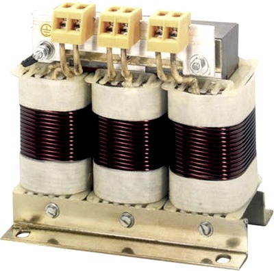
Coils with a significant amount of inductance are made in the form of a transformer with a metal core. They differ from a conventional transformer in the number of windings. In such a coil there is one primary winding, but no secondary.
Peculiarities
- When connecting several coils in a parallel circuit, it is necessary to ensure that they are located on the board from each other as far as possible, in order to avoid the mutual influence of the coils on each other by magnetic fields.
- The distance between turns on a toroidal core does not affect the properties of the inductive coil.
- To create the greatest inductance, the turns on the coil must be wound closely together.
- When using a ferrite cylinder as a core, the center will have the highest inductance.
- The lower the number of turns on the coils, the lower their inductance.
- At sequential circuit connection of coils, the total inductance of the circuit is the sum of the inductances of each coil.
Coil capacity
The turns of the coil winding are separated from each other by a dielectric layer, so they form a kind of capacitor, which is characterized by its capacitance. In coils having several layers of winding, capacitance is formed between the layers. As a result, the coil has the property of not only inductance, but also capacitance.
Most often, the coil capacitance has a negative effect on the elements electrical diagram. Therefore, the coil capacity is disposed of different ways. For example, the coil frame is made of a special shape, and the turns are wound using a special technology. When the coil is wound turn to turn, its capacity also increases.
Oscillatory circuit

If you connect a capacitor and a coil according to the diagram shown in the figure, you get an oscillation circuit that is widely used in radio engineering devices.
If you induce an EMF in a coil or charge a capacitor, then some oscillatory processes will occur in the circuit. When discharged, the capacitor excites a magnetic field in the inductor. When the capacitor's charge is depleted, the coil returns energy back to the capacitor, but with the opposite sign, using self-induction emf. This process is repeated in the form of electromagnetic sinusoidal oscillations.
The frequency of such oscillations is the resonant frequency, depending on the inductance of the coil and the capacitance of the capacitor. Oscillatory circuit, connected in parallel, has significant resistance at the resonance frequency. This makes it possible to use it for frequency selectivity in input circuits in radio equipment, as well as in frequency amplifiers and frequency generator circuits.
With a parallel circuit connecting the oscillation circuit, there are two reactive elements that have different reactivity strengths. The use of this type of circuit allows us to conclude that when parallel connection elements need to be summed only by their conductivity, not their resistance. At the resonance frequency, the sum of the conductivities of the circuit elements is zero, which allows us to talk about the resistance to alternating current tending to infinity.
During 1 period of oscillation of the circuit, energy is exchanged between the coil and the capacitor. In this case, a loop current is formed that significantly exceeds the current in the external circuit.
Inductance and capacitor
Live parts various devices may form inductances. Such parts are fuses, busbars, connecting terminals and other similar parts. If you additionally connect busbars to the capacitor, an inductance is formed, which affects the operation electrical circuit. Also, the performance of the circuit is affected by capacitance and resistance.
The inductance formed at the resonance frequency is calculated by the formula:
C e = C / (1 – 4 Π 2f 2L C), Where C e is the capacitance of the capacitor (effective), f- current frequency, L– coil inductance, WITH– actual capacity, P- Pi".
The amount of inductance must always be taken into account in circuits with power capacitors large capacity. In circuits with pulse capacitors important factor is the value of its own inductance. The discharge of such capacitors occurs into inductive circuits, divided into types:
- Oscillatory.
- Aperiodic.

In a capacitor, the inductance depends on the type of connection of the elements in the circuit. In a parallel circuit, this value is the sum of the inductances of the circuit elements. To reduce inductance electrical device, it is necessary to arrange the current-carrying parts of the capacitor in such a way that the magnetic fluxes are compensated, that is, conductors with one direction of current are located as far as possible from each other, and with opposite direction- next to each other.
By bringing the current-carrying parts closer together and reducing the dielectric layer, it is possible to reduce the inductance of the capacitor section. This is achieved by dividing one section into several small containers.