Connecting LED strip to arduino. Connecting RGB strip via Arduino for control from your phone
In this lesson we will use digital and analog outputs with "pulse width modulation" on the Arduino board to turn on the RGB LED with different shades. Using RGB LED strip allows you to create interior lighting with any shade of color. Let's talk about the device and pinout of a full-color (RGB) LED and consider the directive #define in C++ language.
Design and purpose of an RGB LED
To display the entire palette of shades, three colors are sufficient, using RGB synthesis (Red - red, Green - green, Blue - blue). RGB palette used not only in graphic editors, but also in website building. By mixing colors in different proportions you can get almost any color. The advantages of RGB LEDs are simplicity of design, small dimensions and high efficiency light output
RGB LEDs combine three crystals different colors in one building. RGB LED has 4 pins - one common (the anode or cathode has the longest pin) and three color pins. A resistor must be connected to each color output. In addition, the RGB LED Arduino module can be directly mounted on the board and have built-in resistors - this option is more convenient for classroom activities.
Photo. RGB pinout LED and module with RGB LED for Arduino
The RGB LED pinout is shown in the photo above. Note also that many full-color LEDs require diffusers, otherwise the color components will be visible. Next, we’ll connect an RGB LED to the Arduino and make it glow with all the colors of the rainbow using “pulse width modulation.”
Controlling an RGB LED on Arduino
The analog outputs on the Arduino use "pulse width modulation" to produce different current levels. We can supply all three color inputs on the LED with different PWM signal values in the range from 0 to 255, which will allow us to get almost any shade of light on the RGB LED Arduino.
For this lesson we will need the following details:
- Arduino Uno / Arduino Nano / Arduino Mega board;
- bread board;
- RGB LED;
- 3 resistors 220 Ohm;
- male-female wires.
 Photo. Connection diagram of RGB LED to Arduino on a breadboard
 The RGB LED module can be connected directly to the board, without wires and breadboard. Connect the module with full-color RGB LED to the following pins: Minus- GND B- Pin13, G- Pin12, R— Pin11 (see first photo). If you are using RGB LED (Light Emitting Diode), then connect it according to the diagram in the photo. After connecting the module and assembling the circuit on Arduino, upload the sketch.
Sketch for blinking RGB LED
#define RED 11 // Assign the name RED to pin 11#define GREEN 12 // Assign the name GREEN to pin 12#define BLUE 13 // Assign the name BLUE to pin 13 void setup () ( pinMode(RED, OUTPUT); pinMode(GREEN, OUTPUT); // Use Pin12 for output pinMode(BLUE, OUTPUT); // Use Pin13 for output) void loop () ( digitalWrite (RED, HIGH ); // Turn on the red light digitalWrite(GREEN, LOW); digitalWrite(BLUE, LOW); delay(1000); digitalWrite(RED, LOW); digitalWrite(GREEN, HIGH); // Turn on the green light digitalWrite(BLUE, LOW); delay(1000); // Set a pause for the effect digitalWrite(RED, LOW); digitalWrite(GREEN, LOW); digitalWrite(BLUE, HIGH); // Turn on the blue light delay(1000); // Set a pause for the effect }Explanations for the code:
- Using the #define directive, we replaced the pin numbers 11, 12 and 13 with the corresponding names RED, GREEN and BLUE. This is done for convenience, so as not to get confused in the sketch and understand what color we include;
- in the void setup() procedure we assigned pins 11, 12 and 13 as outputs;
- in the void loop() procedure we turn on all three colors on the RGB LED one by one.
- Using the #define directive, we replaced the pin numbers 9, 10 and 11 with the corresponding names RED, GREEN and BLUE. This is done for convenience, so as not to get confused in the sketch and understand what color we include;
- We used pins 11, 12 and 13 as analogWrite outputs.
Smooth RGB LED control
Controlling an rgb LED on an Arduino can be made smooth using analog outputs with “pulse width modulation”. To do this, the color inputs on the LED must be connected to analog outputs, for example, to pins 11, 10 and 9. And feed them different meanings PWM (PWM) for various shades. After connecting the module using male-female wires, upload the sketch.
Sketch for smooth blinking of an RGB LED
#define RED 9 // Assign the name RED to pin 9#define GREEN 10 // Assign the name GREEN to pin 10#define BLUE 11 // Assign the name BLUE to pin 11 void setup() (pinMode(RED, OUTPUT); // Use Pin9 for output pinMode(GREEN, OUTPUT); // Use Pin10 for output pinMode(BLUE, OUTPUT); // Use Pin11 for output) void loop () ( analogWrite (RED, 50); // Turn on the red light analogWrite(GREEN, 250); // Turn on the green light analogWrite(BLUE, 150); // Turn on the blue light }Explanations for the code:
LED RGB tape It is a flexible tape with conductors and RGB LEDs (full color) printed on it. IN Lately LED strips are widely used in architecture, auto and motorcycle tuning, costumes, decorations, etc. There are also waterproof tapes that can be used, for example, in swimming pools.
LED strips come in two types: analog and digital.
In analog strips, all LEDs are connected in parallel. Therefore, you can set the color of the entire LED strip, but you cannot set a specific color for a specific LED. These tapes are easy to connect and not expensive.
Digital LED strips are a little more complicated. An additional microcircuit is installed for each LED, which makes it possible to control any LED. Such tapes are much more expensive than regular ones.
In this article we will consider working only with analog LED strips.
Analog RGB LED strips
Data sheet:
- 10.5mm width, 3mm thickness, 100mm length of one segment
- waterproof
- 3M tape on the bottom
- max. current consumption (12V, White color) - 60mA per segment
- glow color (wavelength, nm): 630nm/530nm/475nm
RGB LED strip circuit diagram
The tape is supplied in rolls and consists of sections 10 cm long. Each section houses 3 RGB LEDs, size 5050. Each section turns out to contain 9 LEDs: 3 red, 3 green and 3 blue. Section boundaries are marked and contain copper pads. Therefore, if necessary, the tape can be cut and easily soldered. LED strip diagram:

Energy consumption
In each section of the tape, 3 LEDs are connected in series, so 5V power is not suitable. The power supply should be 12V, but you can also supply 9V, but then the LEDs will not burn so brightly.
One segment LED line consumes approximately 20mA when supplied at 12V. That. if you turn on the white color (i.e. red 100%, green 100% and blue 100%), then the power consumption of the section will be about 60mA.
Now, you can easily calculate the current consumption of the entire tape. So, the length of the tape is 1 meter. The tape has 10 sections (10 cm each). The tape consumption with white color will be 60mA*10=600mA or 0.6A. If you use a PWM fade effect between colors, the power consumption can be halved.
Connecting the tape
In order to connect the tape, you need to solder the wires to 4 contact pads. We used a white wire for +12V, and the rest of the colors according to the colors of the LEDs.

Cut off protective film at the end of the tape. From which side the connection will be made is not important, because... symmetrical tape.

Strip the insulation layer to expose the contact pads.

Tin them.

Solder four wires. It is better to use multi-core wire (for example PV3 or PVS cable), it is more flexible.


For protection against water and external influences You can use heat shrink tubing. If the LED strip will be used in a humid environment, then additionally, the contacts can be coated with silicone.


Working with LED strip
The tape can easily be used with any microcontroller. To control LEDs, it is recommended to use pulse width modulation (PWM). Do not connect the tape pins directly to the MK pins, because This is a large current load and the controller may burn out. It's better to use transistors.
You can use NPN transistors or better yet N-channel mosfets. When selecting a transistor, do not forget that the maximum switching current of the transistor must be taken with a reserve.
Connecting LED strip to Arduino controller
Let's look at an example of connecting an LED strip to a popular one. To connect, you can use inexpensive and popular mosfets. You can also use conventional bipolar transistors, for example TIP120. But compared to the mosfet, it has more voltage loss, so it is still recommended to use the former.
The diagram below shows the connection RGB LED tapes when using N-channel mosfets. The mosfet gate is connected to pin1 of the controller, the drain to pin2 and the source to pin3.

Below is a connection diagram when using conventional bipolar transistors(for example TIP120). The base of the transistor is connected to pin1 of the controller, the collector to pin2 and the emitter to pin3. A resistor with a resistance of 100-220 Ohms must be placed between the base and the controller output.

TO Arduino controller connect a power source with a voltage of 9-12 Volts, and +12V from the LED strip must be connected to the Vin pin of the controller. You can use 2 separate power supplies, just do not forget to connect the grounds of the source and the controller.
Example program
To control the tape, the PWM output of the controller will be used, for this you can use the analogWrite() function for pins 3, 5, 6, 9, 10 or 11. With analogWrite(pin, 0) the LED will not light up, with analogWrite(pin, 127 ) the LED will burn at full intensity, and with analogWrite(pin, 255) the LED will burn at maximum brightness. Below is an example sketch for Arduino:
#define REDPIN 5 #define GREENPIN 6 #define BLUEPIN 3 #define FADESPEED 5 // the higher the number, the slower the fade effect will be void setup() ( pinMode(REDPIN, OUTPUT); pinMode(GREENPIN, OUTPUT); pinMode(BLUEPIN , OUTPUT); ) void loop() ( int r, g, b; // fade from blue to purple for (r = 0; r 0; b--) ( analogWrite(BLUEPIN, b); delay(FADESPEED); ) // fade from red to yellow for (g = 0; g 0; r--) ( analogWrite(REDPIN, r); delay(FADESPEED); ) // fade from green to teal for (b = 0; b 0; g--) ( analogWrite(GREENPIN, g); delay(FADESPEED); ) )
This one is simple Arduino project designed for control using PWM (pulse width modulation). It can change the level of each color independently by changing the PWM duty cycle. This way you can create any color by mixing different colors in percentages. Rotating the encoder on the board allows the user to select desired channel and change its brightness. Transistors with low switching resistance create very low heat generation even when using large quantity LEDs. For example, the IRF540 transistor has a very low RDS pass-through resistance - about 70 mOhm.
Tape controller circuit
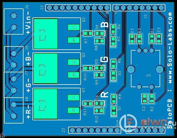
RGB LED is a very common type of LED strip that includes a red, green and blue LED chip in one package. Although they are housed in the same package, each die can be controlled independently. Thanks to this function we can get great amount different colors using RGB LEDs and of course the resulting color can be dynamically changed using a controller.


The main controller is made using Arduino Uno. It reads the input data from the encoder and according to this information, the transistors are switched. The transistors are controlled by pins 9, 10 and 11, which have internal functions PWM The direction of the encoder signals A and B are read using elements 2 and 3, which are connected to the module. The encoder button is used to select the channel and is connected to pin 1, which is set as the input data.
In this article we will talk about color LEDs, the difference between a simple RGB LED and an addressable one, and add information about the areas of application, how they work, how control is carried out with schematic pictures of connecting LEDs.
LEDs – electronic component, capable of emitting light. Today they are widely used in various electronic technology: in flashlights, computers, household appliances, cars, phones, etc. Many microcontroller projects use LEDs in one way or another.
They have two main purposes:
Demonstration of equipment operation or notification of any event;
use for decorative purposes (lighting and visualization).
Inside, the LED consists of red (red), green (green) and blue (blue) crystals assembled in one housing. Hence the name – RGB (Fig. 1).

2. Using microcontrollers
With it you can get many different shades of light. The RGB LED is controlled using a microcontroller (MK), for example, Arduino (Fig. 2).

Of course you can get by a simple block 5 volt power supply, 100-200 ohm resistors to limit the current and three switches, but then you will have to control the glow and color manually. In this case, it will not be possible to achieve the desired shade of light (Fig. 3-4).


The problem arises when you need to connect hundreds of colored LEDs to the microcontroller. The number of pins on the controller is limited, and each LED needs power from four pins, three of which are responsible for color, and the fourth pin is common: depending on the type of LED, it can be an anode or cathode.
3. Controller for RGB control
To unload the MK terminals, special controllers WS2801 (5 volts) or WS2812B (12 volts) are used (Fig. 5).

With the use of a separate controller, there is no need to occupy several MK outputs; you can limit yourself to only one signal output. The MK sends a signal to the “Data” input of the WS2801 LED control controller.
This signal contains 24-bit information about color brightness (3 channels of 8 bits for each color), as well as information for the internal shift register. It is the shift register that allows you to determine which LED the information is addressed to. In this way, you can connect several LEDs in series, while still using one pin of the microcontroller (Fig. 6).

4. Addressable LED
This is an RGB LED, only with an integrated WS2801 controller directly on the chip. The LED housing is made in the form of an SMD component for surface mounting. This approach allows you to place the LEDs as close to each other as possible, making the glow more detailed (Fig. 7).

In online stores you can find addressable LED strips, where up to 144 pieces fit in one meter (Fig. 8).

It is worth considering that one LED consumes only 60-70 mA at full brightness; when connecting a strip, for example, with 90 LEDs, you will need powerful block power supply with a current of at least 5 amperes. Under no circumstances power the LED strip through the controller, otherwise it will overheat and burn out from the load. Use external sources nutrition (Fig. 9).

5. Lack of addressable LEDs
The addressable LED strip cannot operate at too low temperatures: at -15 the controller begins to malfunction; in severe frosts there is a high risk of its failure.
The second drawback is that if one LED fails, all the others along the chain will also refuse to work: the internal shift register will not be able to transmit information further.
6. Application of addressable LED strips
Addressable LED strips can be used for decorative lighting of cars, aquariums, photo frames and paintings, in room design, as New Year's decorations, etc.
It turns out interesting solution, if LED strip is used as background lighting Ambilight for computer monitor (Fig. 10-11).

If you will be using microcontrollers on Arduino based, you will need the FastLed library to simplify working with LED strip ().
Last time we looked at how to connect an LED strip to an Arduino via the L298 driver. Color management was carried out programmatically - the Random function. Now it’s time to figure out how to control the color of the LED strip based on the readings of the DHT 11 temperature and humidity sensor.
The example is based on connecting an LED strip via the L298 driver. Plus, the example has added an LCD 1602 display, which will display the readings of the DHT 11 sensor.
The project will require the following Arduino elements:
- Arduino UNO board.
- Display LCD 1602 + I2C.
- Temperature and Humidity Sensor DHT
- LED Strip Light.
- Driver L298.
- Power supply 9-12V.
- Housing for Arduino and display (optional).
First of all, let's look at the circuit diagram (Fig. 1). On it you can see how to connect all of the above elements. There is nothing complicated in assembling the circuit and connecting it, but it is worth mentioning one nuance that most people forget about and end up getting incorrect results LED work– tapes from Arduino.
Picture 1. Schematic diagram Arduino connections and LED strip with DHT 11 sensor
To avoid correct operation LED strip (flickering, color mismatch, incomplete glow, etc.), the power supply for the entire circuit must be made common, i.e. combine the GND (ground) pins of the Arduino controller and the L298 driver (LED strip). You can see how to do this in the diagram.
A few words about connecting a humidity sensor. If you buy a bare DHT 11, without strapping, then between the first and second contacts, 5V and Data, respectively, you need to solder a resistor with a nominal value of 5-10 kOhm. The temperature and humidity measurement range is written on back side DHT 11 sensor housing. Temperature: 0-50 degrees Celsius. Humidity: 0-80%.
 Figure 2. Correct connection humidity sensor DHT 11
 After assembling all project elements according to the diagram, you need to write program code, which will make it all work the way we need it. And we need the LED strip to change color depending on the readings of the DHT 11 sensor (humidity).
To program the DHT 11 sensor, you will need an additional library.
Arduino and RGB program code - strip. Changes the color of the tape depending on humidity.
#include #include //library for working with LCD display 1602 #include //library for working with the humidity and temperature sensor DHT 11 int chk; //the variable will store all data from the DHT11 sensor int hum; //the variable will store humidity readings from the DHT11 sensor dht11 DHT; //object of type DHT #define DHT11_PIN 4 //Data pin of the DHT11 sensor is connected to input 4 #define LED_R 9 //pin for channel R #define LED_G 10 //pin for channel G #define LED_B 11 //pin for channel B / /variables will store color values //when mixing all three colors the required color will be obtained int led_r=0, led_g=0, led_b=0; //declaring a display object with address 0x27 //don’t forget to use a display in the project via an I2C board LiquidCrystal_I2C lcd(0x27,16,2); void setup() ( //create a display lcd.init(); lcd.backlight(); // declare pins as outputs pinMode(LED_R, OUTPUT); pinMode(LED_G, OUTPUT); pinMode(LED_B, OUTPUT); ) void loop () ( chk = DHT.read(DHT11_PIN);//read data from the DHT11 sensor //output data to the display lcd.print("Temp: "); lcd.print(DHT.temperature, 1); lcd.print( " C"); lcd.setCursor(0,1); lcd.print("Hum: "); lcd.print(DHT.humidity, 1); lcd.print(" %"); delay(1500); / /for correct operation of the sensor, a delay is required for polling lcd.clear(); hum = DHT.humidity; //take humidity readings //give out humidity readings in the range from 19 to 30% green color if ((hum >= 19) && (hum<= 30)) { led_r = 1; led_g = 255; led_b = 1; } //в диапозоне от 31 до 40% влажности выдать красный цвет if ((hum >= 31) && (hum<= 40)) { led_r = 255; led_g = 1; led_b = 1; } //в диапозоне от 41 до 49% влажности выдать синий цвет if ((hum >= 41) && (hum<= 49)) { led_r = 1; led_g = 1; led_b = 255; } // подача сигналов цвета на выхода analogWrite(LED_R, led_r); analogWrite(LED_G, led_g); analogWrite(LED_B, led_b); }
Tags: Tags