Cloud server for controlling Arduino. Blynk: Easy Raspberry and Arduino Control
Last year, Microsoft announced a cloud backend for managing smart appliances and integrated electronics. Azure IoT Hub allows you to set up communication between devices with a minimum of programming and integrate it into your Azure-based projects. To see how this works, we will look at a simple task - sending readings from a sensor connected to an Arduino controller to the cloud.
So, here we have a simple device. It consists of a controller, a small breadboard, a photoresistor (light sensor) and a stabilizing resistor. The controller is a Genuino MKR1000 with built-in Wi-Fi - if you want the same one, it will cost $35. The board is powered by micro-USB.
In principle, any sensor could be installed - this would not affect our future plans in any way. The picture below shows the diagram by which our device will communicate with the cloud.

The device sends data to the IoT Hub, where, after passing through the Stream Analytics service, it enters the database and is processed using Power BI. We'll deal with all these things a little later, but for now let's start with the basics.
INFO
At the end of the article there are sources of the resulting project. Don't forget to check them out if you're planning on doing something similar.
IoT Hub is officially translated into Russian as “Internet of Things Center”. It can both receive data from devices and send messages or commands to them.
In addition to IoT Hub, another service called Event Hub can interact with devices. It has greater throughput, but sends messages only in one direction - from the device to the cloud. IoT Hub supports protocols such as MQTT, MQTT over WebSocket, AMQP, AMQP over WebSocket and HTTP. Event Hub supports AMQP, AMQP over WebSocket and HTTP. You can read more about the difference between hubs and how to use them together on the Microsoft website. We will study the IoT Hub (it’s more interesting).
Previously, I reinvented the wheel of creating an Arduino device for monitoring.
It was interesting.
/* -- New project -- This source code of graphical user interface has been generated automatically by RemoteXY editor. To compile this code using RemoteXY library 2.3.5 or later version download by link http://remotexy.com/en/library/ To connect using RemoteXY mobile app by link http://remotexy.com/en/download/ - for ANDROID 4.3.1 or later version; - for iOS 1.3.5 or later version; This source code is free software; you can redistribute it and/or modify it under the terms of the GNU Lesser General Public License as published by the Free Software Foundation; either version 2.1 of the License, or (at your option) any later version. */ ///////////////////////////////////////////// // RemoteXY include library // //////////////////////////////////////////// // defining the connection mode and including the RemoteXY library #define REMOTEXY_MODE__ESP8266_HARDSERIAL_CLOUD #include
We use a board sandwich.
Unexpectedly, everything worked immediately:

An hour passed from the discovery of the RemoteXY cloud service to the photo above.
Features of working with RemoteXY.
1. Everything is very simple. In its own way this is good. With Blynk and Cayenne, for example, it’s unlikely that you can figure it out from scratch in an hour. To use, for example, "KaScada Cloud" you need to buy a special device.
2. There is no processing and storage of data on the server side: there is no connection with the board - the application displays “No connection”.
3. Only 5 design elements are free, but the PRO application costs no more than half a day of time spent.
4. It is possible to communicate with the board from one application both through a cloud server and directly. True, not at the same time, of course. And it’s impossible to switch quickly - you need to change the sketch on the board. It is also possible to communicate between the smartphone and the board via Bluetooth and USB.
I've been thinking a lot about finding an inexpensive solution to connect and control Arduino over the internet without using any Ethernet shield or even any WI-FI module. After researching, I found that the only way to communicate with the Arduino microcontroller is through its serial port, so I created a simple C# window application as a HUB to work with the serial port to send and receive data to the board.
This HUB application is already connected to the Internet through your personal computer and helps send and receive data between the microcontroller and the cloud database, besides storing the data itself in the online MySQL database.
First of all, I had to start with a small example that allows me to test the application of the idea. In this example I have not connected any sensor, I have only used the built-in LED on the Arduino so that I can turn the LED on pin 13 on and off by sending the letters "I" and "O" to the serial port.
Int input; //Will store the incoming character from the serial port. int led = 13; // Pin 13 // The setup function runs once when you press the reset button or turn on the power int state; void setup() ( // initialize digital pin LED_BUILTIN as output. Serial.begin(9600); pinMode(led, OUTPUT); // Set pin 13 as digital output Serial.flush(); ) // loop function runs again and again always void loop() ( // String input = ""; // while (Serial.available() > 0) // ( // input += (char) Serial.read(); // delay(5 ); // ) state = digitalRead(led); if (Serial.available()) ( input = Serial.read(); if (input == "I") ( //digitalWrite(led, !digitalRead(led) ); digitalWrite(led, HIGH); Serial.println(1); delay(1000); ) else if (input == "O") ( digitalWrite(led, LOW); Serial.println(0); delay(1000 ); ) else if (input == "T") ( analogRead(led); Serial.println(0); delay(1000); ) ) )
Step 2: Create an online database
To store the data, we must use an "online intermediary" that will serve as a bridge between the Arduino board and our HUB application. Therefore, we have chosen free Database hosting, which will work towards saving the data received from the Arduino board and commands sent to it.
The simplest choice in our case is MySQL databases, because... it's free and usually widely used. In the archive attached below, you will find that it only contains two tables. first you need to save the commands, then send them to the board, and the second table is to get the outputs of the Arduino board and restore them for later use.
You can choose freemysqlhosting.net as your hosting site. Online PHP MyAdmin can be found at the link - phpmyadmin.co. More information can also be found on phpmyadmin.net.
Step 3. Create a C# hub

In this step, we will create a hub, which can be thought of as an input filter on the PC, to first pass the data passing through it, then send it to the Arduino board through the serial port and vice versa.

The interface of this hub is very simple, it contains only two text fields that show the status of each "transaction" that transmits the hub data (sending and receiving).
Note. The hub must always be running when you want to work with your Arduino board over the Internet.
Step 4. Create a web interface
We've finally reached the coolest part of the lesson.


I have created a web application based on Asp.net C# technology with a responsive interface that can run on any device, this web application only deals with the online database and does not know that there is any board on the other side.
With this interface you can categorize your electronic components connected to Arduino. By clicking, turning them on and off, you simply store the data online.
Example
By pressing the green button (ON) in the “Living Room” section (Hall - above in the picture), you send an instruction via the Internet to turn on the lights in the living room of your home. Thus, the hub, which may be on the other side of the world, receives the instruction and processes it using an Arduino-based electronic circuit in your home.
Protected void BtnHallOn_Click(object sender, EventArgs e) ( AddTempOrders("I"); // sending letter "I" to Arduino to open Hall light )
Step 5. Download the project
It's time to try it yourself and make your own project.
I hope you find all this useful. I wish you great projects!
ESPers - join the ranks of blinkers!
Today we will set up control of the ESP8266 from your smartphone (iOS or Android) in 5 minutes using the new cloud service Blink. Video and details under the cut.
Install the Blynk app on your smartphone


Register in the application and create a new project.

Enter a project name, for example ESP8266. In field Hardware Model select ESP8266. (hope you'll notice the impressive list of supported hardware) Automatically generated Auth Token send to your mailbox.

After pressing the button Create You will have access to an empty field for designing the UI of your ESP8266 control panel.
![]()
Click on the plus sign at the top right - a toolbar will appear Widget Box to add widgets to your dashboard. It is worth noting that the list of widgets will continue to grow.
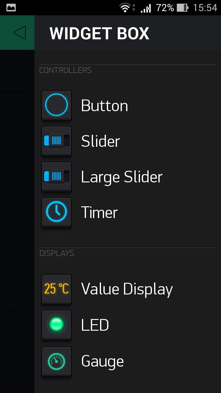
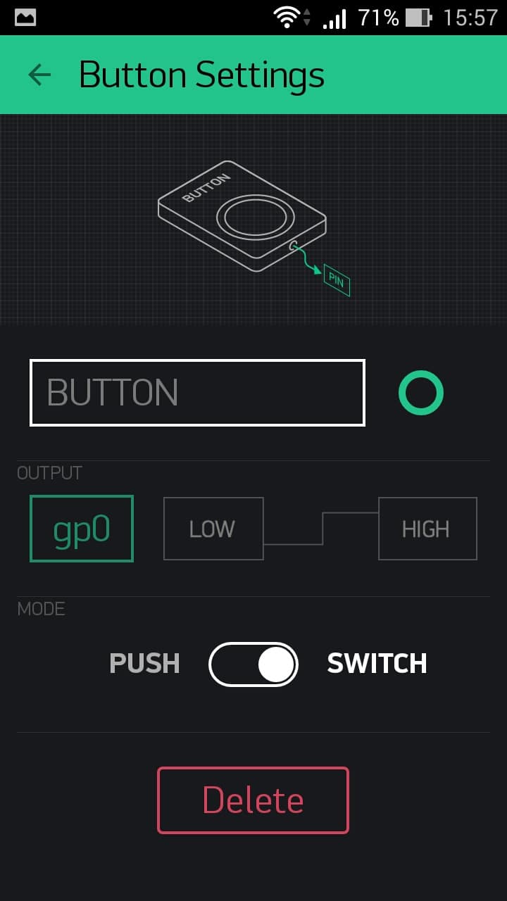
For testing, select the widget type Button— this widget will immediately be added to your panel. Edit it with one touch. You don’t have to fill in the name, just to the right you can select the color of the indicator, in the field OUTPUT PIN select on the right Digital, and on the left is any free pin GPIO. Below, switch the button type to Switch.
Next, install the Blynk library in the Arduino IDE. The official instructions will help you with this. You can also take the latest version of the library directly from the repository and install it manually. Next, choose an example ESP8266_Standalone and write in it Auth Token which we received by mail, SSID and password your WiFi network. Compile and upload the sketch to the ESP8266.
Programming various microcontrollers and microcomputers, such as Arduino, Raspberry Pi and the like, is one of the most interesting and relevant activities. Designing devices on these platforms has gone beyond the hobby of geeks and professional programmers: these boards are used to create robots, machine tools, quadcopters, IoT devices (smart home), servers and even Hi-Fi audio interfaces.
Unfortunately, the microcontroller market is highly segmented. Their programming is carried out through various environments and interfaces. A project called Blynk is called to save the situation.
Blynk is a cloud-based service for creating graphical control panels and is suitable for a wide range of microcomputers and microcontrollers. Where previously in order to collect information from sensors it was necessary to write a full-fledged I/O interface or purchase additional modules, now you can get by with five minutes of work in Blynk.
To create your own project controlled via Blynk, you need very little: install the application (versions for iOS and Android are available) or use the web form. Here you will need to register in one step - enter your email and password. Registration is necessary due to the fact that Blynk is a cloud solution and without it any user can gain control over the hardware.
Those interested can install the server locally. In this case, Internet access is not needed.

The application will require certain skills to operate. First you need to pair your computer or smartphone with the programmable board. The program supports connection with boards through a variety of different interfaces:
- USB (Serial),
- Adafruit CC3000 WiFi,
- Official Arduino WiFi Shield,
- Official Ethernet Shield (W5100),
- ENC28J60,
- ESP8266 (WiFi modem),
- SeeedStudio Ethernet Shield V2.0 (W5200),
- RN-XV WiFly,
- ESP8266.
In addition to setting up the connection, you only need to correctly connect the modules of the future device. After this, in the working form of the application you need to add available modules (widgets), configure the necessary pin addresses and specify the desired parameters (if necessary, you can write your own code). By the way, drag’n’drop is used to create a widget or program. There are a lot of simulators of control devices available for control - switches, sliders, displays, for each of which you can write your own logic. There are separate forms for displaying and organizing information from the required sensors in the form of graphs.
Thus, the platform is suitable for both beginners and more advanced users who do not want to waste time writing applications for project management: from reading data from a weather station and controlling a smart home to controlling robots.
All the information necessary to get started is posted on the official website. Blynk is a , so everyone can contribute to the creation of new features. At the moment, using the service is completely free, in the future the situation will change somewhat - primarily due to the monetization of new functions. Thus, it is already known that access to GPIO interfaces will be purchased as an in-app purchase.
Currently Blynk works with the following boards:
- Arduino: Uno, Nano, Mini, Pro Mini, Pro Micro, Mega, YÚN (Bridge), Due;
- Raspberry Pi;
- Particle (ex Spark Core);
- ESP8266;
- TinyDuino (CC3000);
- Wicked WildFire (CC3000).