Transistor multivibrator circuit with description. LED flasher or how to assemble a symmetrical multivibrator
In this article we present several devices based on one circuit - an asymmetrical multivibrator using transistors of different conductivities.
Using this circuit as a contactless device, you can assemble a device with a flashing light from an electric light bulb (see Fig. 1) and use it for various purposes. For example, install it on a bicycle to power turn lights, or in a model of a lighthouse, a signal light, or on a car. or ship models as a flashing light.

The load of an asymmetrical multivibrator assembled on transistors T1, T2 is light bulb L1. The pulse repetition rate is determined by the capacitance value of capacitor C1 and resistors R1, R2. Resistor R1 limits the maximum flash frequency, and resistor R2 can be used to smoothly change their frequency. You need to start working from the maximum frequency, which corresponds to the top position of the resistor R2 slider in the diagram.
Please note that the device is powered by a 3336L battery, which produces 3.5 V under load, and the L1 light bulb is used at a voltage of only 2.5 V. Will it burn out? No! The duration of its glow is very short, and the thread does not have time to overheat. If the transistors have a high gain, then instead of a 2.5 V x 0.068 A light bulb, you can use a 3.5 V x 0.16 A light bulb. Transistors like MP35-MP38 are suitable for transistor T1, and transistors like MP39-MP42 are suitable for T2.
If you install a loudspeaker in the same circuit instead of a light bulb, you will get another device - an electronic metronome. It is used in teaching music, for keeping time during physical experiments, and in photographic printing.
If you slightly change the circuit - reduce the capacitance of capacitor C1 and introduce resistor R3, then the pulse duration of the generator will increase. The sound will increase (Fig. 2).
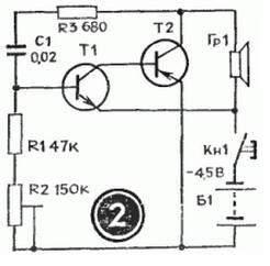
This device can serve as a house bell, a model horn, or a children's pedal car. (In the latter case, the voltage must be increased to 9 V.) And it can also be used for teaching Morse code. Only then, instead of the Kn1 button, you need to install a telegraph key. The sound tone is selected by capacitor C1 and resistor R2. The larger R3, the louder the sound of the generator. However, if its value is more than one kilo-ohm, then oscillations in the generator may not occur.
The generator uses the same transistors as in the previous circuit, and headphones or a head with a coil resistance of 5 to 65 Ohms are used as a loudspeaker.
An asymmetrical multivibrator using transistors of different conductivities has an interesting property: during operation, both transistors are either open or locked at the same time. The current consumed by the switched-off transistors is very small. This makes it possible to create cost-effective indicators of changes in non-electrical quantities, such as humidity indicators. The schematic diagram of such an indicator is shown in Figure 3.

As can be seen from the diagram, the generator is constantly connected to the power source, but does not work because both transistors are locked. Reduces current consumption and resistor R4. A humidity sensor is connected to sockets G1, G2 - two thin tinned wires 1.5 cm long. They are sewn to the fabric at a distance of 3-5 mm from each other. The resistance of the dry sensor is high. When wet it falls. The transistors open, the generator starts working. To reduce the volume, you need to reduce the supply voltage or the value of resistor R3. This humidity indicator can be used when caring for newborn babies.
If you expand the circuit a little, the humidity indicator will emit light simultaneously with the sound signal - light bulb L1 will start to light up. In this case, as can be seen from the diagram (Fig. 4), two asymmetrical multivibrators on transistors of different conductivities are installed in the generator. One is assembled on transistors T1, T2 and is controlled by a humidity sensor connected to sockets G1, G2. The load of this multivibrator is lamp L1. The voltage from the collector T2 controls the operation of the second multivibrator, assembled on transistors T3, T4. It works as an audio frequency generator, and loudspeaker Gr1 is turned on at its output. If there is no need to give a sound signal, then the second multivibrator can be turned off.

The transistors, lamp and loudspeaker used in this humidity indicator are the same as in previous devices.
Interesting devices can be built using the dependence of the frequency of an asymmetrical multivibrator on transistors of different conductivity on the base current of transistor T1. For example, a generator that simulates the sound of a siren. Such a device can be installed on a model of an ambulance, fire truck, or rescue boat.
The schematic diagram of the device is shown in Figure 5.

In the initial position, the Kn1 button is open. Transistors are locked. The generator is not working. When the button is closed, capacitor C2 is charged through resistor R4. The transistors open and the multivibrator starts working. As capacitor C2 charges, the base current of transistor T1 increases and the frequency of the multivibrator increases. When the button is opened, everything repeats in the reverse order. The siren sound is simulated by periodically closing and opening the button. The rate of rise and fall of sound is selected by resistor R4 and capacitor C2. The siren tone is set by resistor R3, and the sound volume by selecting resistor R5. The transistors and loudspeaker are selected the same as in previous devices.
Considering that this multivibrator uses transistors of different conductivities, you can use it as a device for testing transistors by replacement. The schematic diagram of such a device is shown in Figure 6. The circuit of a sound generator is taken as a basis, but a light pulse generator can be used with equal success.

Initially, by closing the Kn1 button, check the operation of the device. Depending on the type of conductivity, connect the transistor under test to sockets G1 - G3 or G4-G6. In this case, use switch P1 or P2. If there is sound in the loudspeaker when you press the button, then the transistor is working.
As switches P1 and P2, you can take toggle switches with two switching contacts. The figure shows the switches in the "Control" position. The device is powered by a 3336L battery.

If you look at it, all electronics consists of a large number of individual bricks. These are transistors, diodes, resistors, capacitors, inductive elements. And from these bricks you can build anything you want.
From a harmless children's toy that makes, for example, the sound of “meow”, to the guidance system of a ballistic missile with a multiple warhead for eight megaton charges.
One of the very well-known and often used circuits in electronics is a symmetrical multivibrator, which is an electronic device that produces (generates) oscillations in shape, approaching rectangular.
The multivibrator is assembled on two transistors or logic circuits with additional elements. Essentially, this is a two-stage amplifier with a positive feedback circuit (POC). This means that the output of the second stage is connected through a capacitor to the input of the first stage. As a result, the amplifier turns into a generator due to positive feedback.
In order for the multivibrator to start generating pulses, it is enough to connect the supply voltage. Multivibrators can be symmetrical And asymmetrical.
The figure shows a circuit of a symmetrical multivibrator.

In a symmetrical multivibrator, the values of the elements of each of the two arms are absolutely the same: R1=R4, R2=R3, C1=C2. If you look at the oscillogram of the output signal of a symmetrical multivibrator, it is easy to notice that the rectangular pulses and pauses between them are the same in time. t pulse ( t and) = t pause ( t p). Resistors in the collector circuits of transistors do not affect the pulse parameters, and their value is selected depending on the type of transistor used.

The pulse repetition rate of such a multivibrator is easily calculated using a simple formula:
Where f is the frequency in hertz (Hz), C is the capacitance in microfarads (µF) and R is the resistance in kilo-ohms (kOhm). For example: C = 0.02 µF, R = 39 kOhm. We substitute it into the formula, perform the actions and get a frequency in the audio range approximately equal to 1000 Hz, or more precisely 897.4 Hz.
In itself, such a multivibrator is uninteresting, since it produces one unmodulated “squeak”, but if the elements select a frequency of 440 Hz, and this is the A note of the first octave, then we will get a miniature tuning fork, with which you can, for example, tune a guitar on a hike. The only thing you need to do is add a single transistor amplifier stage and a miniature speaker.
The following parameters are considered to be the main characteristics of a pulse signal:
Frequency. Unit of measurement (Hz) Hertz. 1 Hz – one oscillation per second. Frequencies perceived by the human ear are in the range of 20 Hz – 20 kHz.
Pulse duration. It is measured in fractions of a second: miles, micro, nano, pico and so on.
Amplitude. In the multivibrator under consideration, amplitude adjustment is not provided. Professional devices use both step and smooth amplitude adjustment.
Duty factor. The ratio of the period (T) to the pulse duration ( t). If the pulse length is 0.5 periods, then the duty cycle is two.

Based on the above formula, it is easy to calculate a multivibrator for almost any frequency with the exception of high and ultra-high frequencies. There are slightly different physical principles at work there.
In order for the multivibrator to produce several discrete frequencies, it is enough to install a two-section switch and five or six capacitors of different capacities, naturally identical in each arm, and use the switch to select the required frequency. Resistors R2, R3 also affect the frequency and duty cycle and can be made variable. Here is another multivibrator circuit with adjustable switching frequency.

Reducing the resistance of resistors R2 and R4 to less than a certain value, depending on the type of transistors used, can cause generation failure and the multivibrator will not work, therefore, in series with resistors R2 and R4, you can connect a variable resistor R3, which can be used to select the switching frequency of the multivibrator.
The practical applications of a symmetrical multivibrator are very extensive. Pulse computing technology, radio measuring equipment in the production of household appliances. A lot of unique medical equipment is built on circuits based on the same multivibrator.
Due to its exceptional simplicity and low cost, the multivibrator has found wide application in children's toys. Here is an example of a regular LED flasher.

With the values of electrolytic capacitors C1, C2 and resistors R2, R3 indicated in the diagram, the pulse frequency will be 2.5 Hz, which means the LEDs will flash approximately twice per second. You can use the circuit proposed above and include a variable resistor together with resistors R2, R3. Thanks to this, it will be possible to see how the flash frequency of the LEDs will change when the resistance of the variable resistor changes. You can install capacitors of different ratings and observe the result.
While still a schoolboy, I assembled a Christmas tree garland switch using a multivibrator. Everything worked out, but when I connected the garlands, my device began to switch them with a very high frequency. Because of this, the TV in the next room began to show wild interference, and the electromagnetic relay in the circuit crackled like a machine gun. It was both joyful (it works!) and a little scary. The parents were quite alarmed.
Such an annoying mistake with too frequent switching did not give me peace. And I checked the circuit, and the capacitors were at their nominal value. I didn't take into account only one thing.
The electrolytic capacitors were very old and dried out. Their capacity was small and did not at all correspond to what was indicated on their body. Due to the low capacitance, the multivibrator operated at a higher frequency and switched the garlands too often.
At that time I did not have instruments that could measure the capacitance of capacitors. Yes, and the tester used a pointer, and not a modern digital multimeter.
Therefore, if your multivibrator produces an excessive frequency, then first check the electrolytic capacitors. Fortunately, now you can buy a universal radio component tester for little money, which can measure the capacitance of a capacitor.
A transistor multivibrator is a square wave generator. Below in the photo is one of the oscillograms of a symmetrical multivibrator.
A symmetrical multivibrator generates rectangular pulses with a duty cycle of two. You can read more about duty cycle in the article frequency generator. We will use the operating principle of a symmetrical multivibrator to alternately turn on the LEDs.

The scheme consists of:
– two KT315B (can be with any other letter)
– two capacitors with a capacity of 10 microFarads
– four, two 300 Ohm each and two 27 KiloOhm each
– two Chinese 3 Volt LEDs

This is what the device looks like on a breadboard:

And this is how it works:
To change the blinking duration of the LEDs, you can change the values of capacitors C1 and C2, or resistors R2 and R3.
There are also other types of multivibrators. You can read more about them. It also describes the operating principle of a symmetrical multivibrator.
If you are too lazy to assemble such a device, you can buy a ready-made one;-) I even found a ready-made device on Alika. You can look it up at this link.
Here is a video that describes in detail how a multivibrator works:
This article describes a device designed simply so that a novice radio amateur (electrician, electronics engineer, etc.) can better understand the circuit diagrams and gain experience during the assembly of this device. Although it is possible that this simplest multivibrator, which is described below, can also find practical application. Let's look at the diagram:
Figure 1 - The simplest multivibrator on a relay
When power is applied to the circuit, the capacitor begins to charge through resistor R1, the contacts K1.1 are open, when the capacitor is charged to a certain voltage, the relay will operate and the contacts close, when the contacts are closed, the capacitor will begin to discharge through these contacts and resistor R2, when the capacitor is discharged to a certain voltage, the contacts will open and the process will then be repeated cyclically. This multivibrator works because the relay operating current is greater than the holding current. The resistance of the resistors CANNOT be changed within wide limits and this is a disadvantage of this circuit. The resistance of the power supply affects the frequency and because of this, this multivibrator will not work from all power sources. The capacitance of the capacitor can be increased, but the frequency of contact closure will decrease. If the relay has a second group of contacts and large capacitance values are used, then this circuit can be used to periodically automatically turn on/off devices. The assembly process is shown in the photos below:

Connecting resistor R2

Connecting a capacitor

Connecting resistor R1

Connecting the relay contacts to its winding

Connecting wires for power supply

You can buy a relay at a radio parts store or get it from old broken equipment. For example, you can desolder relays from boards from refrigerators:


If the relay has bad contacts, you can clean them a little.
Hello dear friends and all readers of my blog site. Today's post will be about a simple but interesting device. Today we will look at, study and assemble an LED flasher, which is based on a simple rectangular pulse generator - a multivibrator.
When I visit my blog, I always want to do something special, something that will make the site memorable. So I present to your attention a new “secret page” on the blog.
This page now bears the name “This is interesting.”
You probably ask: “How can I find it?” And it's very simple!
You may have noticed that there is a kind of peeling corner on the blog with the inscription “Hurry here”.

Moreover, as soon as you move the mouse cursor to this inscription, the corner begins to peel off even more, revealing the inscription - the link “This is interesting”.

It leads to a secret page where a small but pleasant surprise awaits you - a gift prepared by me. Moreover, in the future this page will contain useful materials, amateur radio software and something else - I haven’t thought of it yet. So, periodically look around the corner - in case I hid something there.
Okay, I got a little distracted, now let's continue...
In general, there are many multivibrator circuits, but the most popular and discussed is the astable symmetrical multivibrator circuit. She is usually depicted this way.

For example, I soldered this multivibrator flasher about a year ago from scrap parts and, as you can see, it flashes. It blinks despite the clumsy installation done on the breadboard.
This scheme is working and unpretentious. You just need to decide how it works?
Multivibrator operating principle
If we assemble this circuit on a breadboard and measure the voltage with a multimeter between the emitter and collector, what will we see? We will see that the voltage on the transistor either rises almost to the voltage of the power supply, then drops to zero. This suggests that the transistors in this circuit operate in switch mode. I note that when one transistor is open, the second is necessarily closed.
The transistors are switched as follows.
When one transistor is open, say VT1, capacitor C1 discharges. Capacitor C2, on the contrary, is quietly charged with the base current through R4.
During the discharge process, capacitor C1 keeps the base of transistor VT2 under negative voltage - it locks it. Further discharge brings capacitor C1 to zero and then charges it in the other direction.
Now the voltage at the base of VT2 increases, opening it. Now capacitor C2, once charged, is subject to discharge. Transistor VT1 turns out to be locked with negative voltage at the base.
And all this pandemonium continues non-stop until the power is turned off.
Multivibrator in its design
Having once made a multivibrator flasher on a breadboard, I wanted to refine it a little - make a normal printed circuit board for the multivibrator and at the same time make a scarf for the LED indication. I developed them in the Eagle CAD program, which is not much more complicated than Sprintlayout but has a strict connection to the diagram.

Multivibrator printed circuit board on the left. Electrical diagram on the right.

Printed circuit board. Electric scheme.
I printed the drawings of the printed circuit board on photo paper using a laser printer. Then, in full accordance with the folk tradition, he etched the scarves. As a result, after soldering the parts, we got scarves like this. 
To be honest, after complete installation and connecting the power, a small bug occurred. The plus sign made from LEDs did not blink. It burned simply and evenly as if there was no multivibrator at all.
I had to be pretty nervous. Replacing the four-point indicator with two LEDs corrected the situation, but as soon as everything was returned to its place, the flashing light did not blink.
It turned out that the two LED arms were connected by a jumper; apparently, when I tinned the scarf, I went a little overboard with the solder. As a result, the LED “hangers” lit up synchronously rather than at intervals. Well, nothing, a few movements with a soldering iron corrected the situation.
I captured the result of what happened on video:
In my opinion it turned out not bad. 🙂 By the way, I’m leaving links to diagrams and boards - enjoy them for your health.
Multivibrator board and circuit.
Board and circuit of the "Plus" indicator.
In general, the use of multivibrators is varied. They are suitable not only for simple LED flashers. After playing with the values of resistors and capacitors, you can output audio frequency signals to the speaker. Wherever a simple pulse generator may be needed, a multivibrator is definitely suitable.
It seems that I told everything that I planned. If you missed something, write in the comments - I’ll add what’s needed, and what’s not needed, I’ll correct it. I'm always happy to receive comments!
I write new articles spontaneously and not according to a schedule, and therefore I suggest subscribing to updates by email or email. Then new articles will be sent directly to your inbox or straight to your RSS reader.
That's all for me. I wish you all success and a good spring mood!
Best regards, Vladimir Vasiliev.
Also, dear friends, you can subscribe to site updates and receive new materials and gifts directly to your mailbox. To do this, just fill out the form below.