HF power amplifier on cheap field devices IRF-IRL. Power amplifier on IRF630 for HF radio station The rings are wrapped with a layer of varnished cloth before winding
Transcript
1 33 POWERFUL AMPLIFIER WITH 4 FIELD TRANSISTORS The circuit below allows you to obtain a given output power with minimal losses when summing the output signals. To obtain higher output power values, it is possible to connect two or more field-effect transistors MRF150 from Motorola in parallel. This connection method is practically not used for bipolar transistors due to their low input impedance. In a common-source circuit, high-power field-effect transistors have approximately a times higher input resistance than a bipolar transistor of comparable power connected in a common-emitter circuit. The output impedance value depends on the supply voltage and output power level. The number of transistors connected in parallel is limited by physical factors rather than by electrical factors; the total inductance of the transistor leads is the most significant reason limiting the maximum operating frequency. The effect of lead inductance increases as the supply voltage decreases and the output power increases. Since the minimum distance between transistors is limited by the size of their housings, a practically feasible improvement is to reduce the size of the transistors. At higher frequencies, the transistor lead inductance can be used as part of a distributed circuit, but this severely limits the operating frequency range. Such circuits are widely used in microwave devices based on bipolar transistors. When connecting power MOSFETs in parallel, another important aspect must be taken into account. If the unity gain frequency (f) of the transistor is high enough, then the amplifier can turn into a generator, the resonant system of which will be formed by the inductances of the gate terminals and the drain-source capacitances of the transistors. Positive feedback is carried out through the drain-gate feedthrough capacitance. The resulting phase shift of 360 occurs at frequencies typically above the amplifier's operating range. Thus, the resulting oscillations may be absent at the output of the PA, but have a significant amplitude at the drains of the transistors. Generation can be eliminated by reducing to the minimum possible values the inductance in the gate circuit, consisting of the inductances of the terminals of the separating capacitors C7...C10 (Fig. 1) and the terminals of the transistor gates. The use of low-resistance non-inductive resistors R15...R18 does not reduce the gain in the operating frequency range and makes it possible to achieve better RA stability. Description of the circuit diagram Figure 1 shows the complete circuit of a power amplifier using field-effect transistors. The supply voltage can be V and depends on the linearity requirements of the device. The bias voltage is set for each transistor separately, so there is no need to select transistors based on the cutoff voltage value. The power gain of MOS transistors is significant. Fig. 1
4 36 AUGUST Fig. 6 Curie ry. On the other hand, it is quite difficult to find magnetic cores with low µi and large cross-sectional areas. To achieve the minimum inductance value required for a frequency of 2 MHz, two transformers on the lines are connected in series. Both have a resistance transformation ratio of 9:1. You can use a parallel connection of the secondary windings of the transformer, doubling the number of turns in each winding. C11 must be designed for large values of reactive current to flow through it. Structurally, C11 is fixed directly across the turn of the primary winding of the transformer. The use of parallel connection of ceramic or mica capacitors with lower capacitance values is not recommended. Design features Due to the close arrangement of four MOS transistors, it was not possible to provide effective grounding at high frequencies, as a result of which the gain at a frequency of 30 MHz is reduced by 1.0...1.5 dB (Fig. 4). The situation can be improved by connecting all grounded terminals of the transistors with a conductive strip. Another method is to place petals under the screws holding the transistors, which are soldered to the nearest ground point. In this case, the radiator is used as a high-frequency ground. Although the value of 3rd order intermodulation distortion coefficient is not very high (Fig. 4), for 5th order intermodulation products this coefficient is better than -30 dB at all frequencies. You can also expect the suppression of 9th and higher order intermodulation products to be between -50 and -60 dB. It is also clear that the intermodulation coefficient remains constant as the output power decreases, in contrast to PA circuits made on bipolar transistors, where an increase in intermodulation distortion is observed. The content of harmonic components in the spectrum of the output signal of the amplifier very much depends, as in other similar balanced devices, on the balancing of the arms of the push-pull cascade. The situation is worst at low frequencies, where the suppression of the second harmonic is dB. Suppression of the 3rd harmonic component of the output signal at a carrier frequency of 6.0...8.0 MHz is 12 dB. In this case, it is necessary to use signal harmonic filters, the description and design of which can be found in the literature. The amplifier remains stable with an output mismatch of 3:1, as well as with a decrease in supply voltage. In MOS transistors connected in a common-source circuit, the transmission coefficient in the feedback circuit is several times higher than that of bipolar transistors connected in a common-emitter circuit. As a result, a properly designed MOSFET amplifier is more stable, especially under varying load conditions. Particular attention should be paid to the design of the radiator, which must ensure effective heat removal from the transistors. With an output power of W, it is necessary to use cooling radiators made of a material with high thermal conductivity, such as copper. It is possible to use a combined radiator, which has copper inserts in the places where the transistors are mounted, and the rest is made of aluminum alloy. The places where the transistors are attached should have a smooth (polished) surface, which should preferably be lubricated with a heat-conducting lubricant. Figures 5 and 6 show the printed circuit boards of the amplifier. Based on Motorola RF Application Reports.
6 38 AUGUST resistance to create partial automatic displacement. The operating frequency at which generator lamps can operate reliably should not exceed the value indicated in the handbook as a limit, as this leads to the following undesirable phenomena. 1. The temperature regime of the lamp is disrupted due to an increase in high-frequency losses on the electrodes, cylinder and electrode terminals. Overheating of the mesh and glass-metal junctions can lead to the formation of local mechanical tensions and microcracks, which causes loss of vacuum and lamp failure. The total amount of heat generated at the glass-metal junctions and at the electrode terminals is proportional to the frequency to the power of 2.5 and the instantaneous value of the square of the potential difference between the anode and the grid. 2. The output parameters of the lamps (power and efficiency) decrease due to an increase in the angle of flight of electrons. 3. The danger of self-excitation of lamps increases due to an increase in intra-lamp connections. The required operating temperature conditions for high-power generator lamps and some types of medium-power generator lamps are achieved using one of three types of forced cooling: air, water and evaporation. Air cooling is the easiest to use and allows you to reduce the anode temperature to 250 C. When using generator lamps with this type of cooling, you must follow the following recommendations. The cooling air must be dry and clean. If water or oil gets into the air channel and settles on the glass, it can damage the lamp. The amount of air supplied for cooling must be no less than the norm given in the reference book for each type of lamp. The air flow for cooling the glass bulb of the lamp and the leg must be directed in such a way that the temperature of the glass does not exceed 150 C anywhere and does not create zones with sharp temperature changes across the surface of the glass. When supplying air for cooling from fans located in close proximity to lamps, special measures should be taken to protect them from vibrations, for example, air ducts should be connected through flexible connections, soft rubber or silk hoses, etc. Water cooling of lamps in some cases makes it possible to slightly increase the power dissipated by the anode, since with this type of cooling it is possible to reduce the anode temperature to 120 C. Powerful water-cooled generator lamps are immersed in a tank with running cooling water. Water consumption per 1 kW of power removed from the anode surface depends on the power of the lamp, its design and the design of the tank and varies within l/min. When using water-cooled generator lamps, the following rules must be applied. Cooling water must be clean and free of mineral impurities. It is recommended to cool the anodes with distilled water. Water with a hardness exceeding 0.17 g/l and having a resistance of less than 4 lumps per 1 cm 3 should not be consumed. For uniform cooling of the anodes, the water flow washing the anode must be directed from bottom to top. In this case, it is necessary that the density of the water flow around the entire working surface of the anode is uniform and that no air cushion is formed. The influx and drainage of water from the grounded section of the pipeline to the cooled parts of the lamp, which are energized in relation to the ground, must be carried out through pipelines made of insulating material of the required length, so that the water column placed in them has a sufficiently large resistance and leakage current was minimal. The length of the insulated pipeline is usually selected depending on the resistivity of the water at the rate of 0.3...0.6 m per 1 kV of voltage. The amount of water supplied for cooling must be sufficient and comply with the standards specified in the directory for each type of lamp. To avoid intensive scale formation, the temperature of the outlet water should not exceed 70 C. Evaporative cooling differs from water cooling in that the heat generated by the anode goes mainly to evaporate water. This type of cooling is more economical, since transferring water to the vapor phase requires more heat than heating it from normal temperature to boiling. To increase the cooling surface and improve its wettability with water, the anode radiator of the evaporatively cooled lamp has conical teeth. In the depressions between the teeth, the temperature of the anode surface is the highest and the water that gets there turns into steam bubbles, which are ejected from the depression, giving way to water, etc. This type of cooling allows you to remove up to 500 W of power from 1 cm 2 of the anode surface. With a further increase in power, a vapor film is formed and heat transfer deteriorates. The remaining requirements for the operation of generator lamps with evaporative cooling are similar to the requirements for the operation of generator lamps with water cooling. In addition to the above-mentioned features of the use of generator lamps, it is also necessary to observe the following recommendations for the operation of generator lamps. 1. Radio devices that use generator lamps must provide special devices for protecting generator lamps in emergency conditions of the equipment (lack of cooling, significant excess of permissible currents, etc.). It should be ensured that in the absence of at least one type of cooling, the supply voltages are turned off and cannot be turned on. The cooling system must use hydraulic contacts that respond not to changes in pressure, but to changes in coolant flow. In the anode circuits and grids of powerful generator lamps, devices must be provided that turn off the supply voltage to the electrodes when the maximum current values are exceeded by 2.5...3 times or limit the discharge current. The following devices can be used: - high-speed relays (operation time no more than 100 ms), causing a disconnection of the corresponding power source or a break in the primary winding of the supply transformer (for industrial-type installations with a power of no more than kW); - shunting lamps in the event of breakdown by gas-discharge or other devices with low internal resistance; - inclusion of a limiting resistance in the anode circuit, which reduces the discharge current.
7 39 To prevent destruction of a powerful generator lamp (with a power of more than 15 kW) when a discharge occurs in it, if a power source with a capacitive filter is used in parallel with the anode circuit, it is necessary to install high-speed electronic protection. To avoid overloads of the control and shielding grids, the protection circuit must provide for the simultaneous removal of the excitation voltage and the supply voltage of the shielding grid when the anode voltage is turned off. It is also necessary to provide for changes in the modes of the preliminary stage lamps after the output stage protection is triggered. 2. Putting the generator lamp into operation and supplying voltage to the electrodes must be done in the following sequence: - after connecting all the electrodes, all types of cooling of the lamp and equipment elements are turned on; - the filament voltage is turned on, and it is necessary to control that the starting current does not exceed the value specified in the reference book, or does not exceed more than one and a half times the rated value (for medium and high power generator lamps); - the voltage that locks the lamp is turned on; - the voltage of the anode and the shielding grid of the lamp is turned on (smoothly or in steps in accordance with the operating instructions), while turning on the voltage of the shielding grid earlier than the anode is strictly prohibited; - alternating voltages are turned on (excitation or modulation), and constant voltages are brought to nominal values. Turning off the lamp is done in the reverse order. To ensure that when the excitation is removed, the constant voltages do not exceed the maximum permissible values, it is recommended to first reduce them if necessary. Forced cooling of all types for general lamps should stop only one minute after turning off the filament voltage, unless another time is specified in the technical documentation for a specific type of lamp. It is forbidden to turn on the high voltage of the anode and screen grid when the filament voltage is turned on, as this can damage the lamp due to breakdown and destruction of the cathode. 3. To improve the vacuum and restore the electrical strength of generator lamps, in some cases, special training is used, which must be carried out when the lamp is first turned on and during long breaks (up to 3 months) in operation, as well as periodically (once every 3 months) when storage, if indicated in the passport or label on the lamp. Training is usually carried out in a device in which a lamp operates. The lamp is installed in the circuit, and filament and bias voltages are applied to it in the usual sequence. The lamp is kept in this mode for 30 minutes. Then voltages are applied to the remaining electrodes, equal to approximately half of their nominal value, so that the power dissipated at the anode and other electrodes is 0.4...0.5 power in the nominal mode. After minutes (depending on the size of the internal fittings of the lamp), the voltage of the anode and other electrodes is gradually or in steps brought up to the nominal voltage (with a minute delay at each step) and maintained for at least 30 minutes. When breakdowns occur, the anode voltage decreases until they stop and is maintained in this mode for min, after which it increases again. This training is carried out until breakdowns disappear at full operating anode voltage. To protect the lamp from damage as a result of breakdowns during training, a resistance several times higher than the usual limiting resistance is usually included in the anode circuit of the lamp. 4. The operating position of generator lamps, as a rule, should be vertical, and for generator lamps of medium and higher power this rule is mandatory. 5. In cases of connecting a lamp to a generator circuit when working with lamps in the VHF and HF ranges, it is necessary to establish reliable and uniform electrical contact around the perimeter of the outer part of the electrodes and maintain alignment, eliminating radial stress and bending forces in the leads and mounting elements of the lamps. In addition, it is necessary to use a design of the anode circuit that would prevent the dielectric of the cylinder from developing an increased concentration of high-frequency field lines in one place, since local overheating that appears in these cases can cause its softening and puncture (vacuum violation). The same result can be caused by poor contact with the terminals due to overheating of the glass-to-metal junctions. Mounting of medium and high power generator lamps in equipment should only be done at the anode flange, tank or radiator. It is prohibited to use the remaining terminals of the lamp for this purpose, since their designs, as a rule, are not designed to withstand heavy loads. 6. The design of elements directly in contact with the terminals of the lamp should be carried out in such a way as to ensure reliable electrical and thermal contacts. 7. When operating generator lamps, especially for high-power lamps, it should be remembered that the mode in which filament voltage is applied to the lamp without current extraction is more severe for the cathode compared to the normal operating mode. Therefore, during breaks in the operation of the equipment from 30 minutes to 2 hours, it is recommended to reduce the filament voltage by % of the nominal value. For longer breaks in operation, the generator lamp should be put into operation gradually, i.e. carry out a training cycle. 8. If it is necessary to use generator lamps designed for continuous operation in pulsed mode, one can proceed from the following considerations: in the range of pulse durations from 0.1 μs to 1 ms, recalculation of the electrical operating mode of the lamps should be based on the inadmissibility of exceeding the average powers dissipated by electrodes. If the pulse duration is more than 1 ms, recalculation can only be done taking into account thermal heating during the pulse passage. An increase in the constant voltages on the electrodes of generator lamps intended for operation in continuous mode relative to the operating values in the case of their use in a mode with pulse grid modulation is not allowed. 9. When using pulsed generator and modulator lamps, it is strictly prohibited to use them in pulse modes exceeding those specified in the reference book as limits, for example, reducing the duty cycle or increasing the pulse duration at the maximum anode current.
RU9AJ "HF and VHF" 5 2001 Power amplifier based on GU-46 tubes The glass pentode GU-46 is becoming increasingly popular among shortwave operators, on which RU9AJ built a powerful amplifier for all amateur
Fundamentals of circuit design FUNDAMENTALS OF CIRCUIT DESIGN...1 1. BASIC PROVISIONS...1 2. Amplification OF WEAK SIGNALS...6 3. Amplification OF STRONG SIGNALS...14 4. FUNDAMENTALS OF AMPLIFIER CIRCUIT DESIGN...18 1. Fundamentals
Lecture 8 Topic 8 Special amplifiers Direct current amplifiers Direct current amplifiers (DC amplifiers) or amplifiers of slowly varying signals are amplifiers that are capable of amplifying electrical
POWER SUPPLY IPS-1000-220/110V-10A IPS-1500-220/110V-15A IPS-1000-220/220V-5A IPS-1500-220/220V-7A DC(AC) / DC-1000-220/110V -10A (IPS-1000-220/110V-10A(DC/AC)/DC) DC(AC) / DC-1500-220/110V-15A (IPS-1500-220/110V-15A(DC/AC)/ DC)
3.1 General information 3 Monoblock MB01 The X-ray power supply device IEC-F7 includes a monoblock, which includes a high-voltage transformer-rectifier unit, a filament transformer and an X-ray
STABILIZED POWER SUPPLIES IPS-1000-220/24V-25A IPS-1200-220/24V-35A IPS-1500-220/24V-50A IPS-950-220/48V-12A IPS-1200-220/48V-25A IPS- 1500-220/48V-30A IPS-950-220/60V-12A IPS-1200-220/60V-25A
STABILIZED POWER SUPPLIES IPS-300-220/110V-4A-1U-D IPS-300-220/110V-4A-1U-E IPS 300-220/110V-4A-1U-DC(AC)/DC IPS 300-220 /110V-4A-1U-DC(AC)/DC-E IPS-300-220/220V-2A-1U-D IPS-300-220/220V-2A-1U-E
Laboratory work 6 Study of the local oscillator board of a professional receiver Purpose of the work: 1. To become familiar with the circuit diagram and design of the local oscillator board. 2. Remove the main characteristics
Page 1 of 8 6P3S (output beam tetrode) The main dimensions of the 6P3S lamp. General data The 6PCS beam tetrode is designed to amplify low frequency power. Applicable in single-stroke and push-pull outputs
STABILIZED POWER SOURCE IPS-500-220V/24V-15A-D (AC(DC)/DC) IPS-500-220V/48V-10A-D (AC(DC)/DC) IPS-500-220V/60V-8A -D (AC(DC)/DC) IPS-500-220V/110V-4A-D (AC(DC)/DC) IPS-500-220V/220V-2A-D (AC(DC)/DC)
Lecture 7 Topic: Special amplifiers 1.1 Power amplifiers (output stages) Power amplification stages are usually output (final) stages to which an external load is connected, and are designed
STABILIZED POWER SUPPLIES IPS-300-220/24V-10A IPS-300-220/48V-5A IPS-300-220/60V-5A DC/DC-220/24B-10A (IPS-300-220/24V-10A ( DC/AC)/DC)) DC/DC-220/48B-5A (IPS-300-220/48V-5A (DC/AC)/DC)) DC/DC-220/60B-5A
Fundamentals of the functioning of converter electronics Rectifiers and inverters RECTIFIERS ON DIODES Indicators of rectified voltage are largely determined by both the rectification circuit and the used
STABILIZED POWER SOURCE IPS-500-220V/220V-2A-D IPS-500-220V/110V-4A-D IPS-500-220V/60V-8A-D IPS-500-220V/48V-10A-D IPS-500 -220V/24V-15A-D AC(DC)/DC operating instructions CONTENTS 1.
WIDEBAND POWER AMPLIFIER WITH OVERLOAD PROTECTION Alexander Titov (Schemotekhnika, 2005, 8, p. 52 55) Home address: 634050, Russia, Tomsk, Lenin Ave., 46, apt. 28. Tel. 51-65-05, E-mail: [email protected]
4. Long lines 4.1. Signal propagation along a long line When transmitting pulsed signals over a two-wire line, it is often necessary to take into account the finite speed of signal propagation along the line.
95 Lecture 0 PULSE VOLTAGE REGULATORS Plan. Introduction. Buck switching regulators 3. Boost switching regulators 4. Inverting switching regulator 5. Losses and efficiency of switching regulators
STABILIZED POWER SUPPLIES IPS-1000-220/24V-25A-2U IPS-1200-220/24V-35A-2U IPS-1500-220/24V-50A-2U IPS-2000-220/24V-70A-2U IPS-950 -220/48V-12A-2U IPS-1200-220/48V-25A-2U IPS-1500-220/48V-30A-2U
ILT, ILT thyristor control modules Converter circuits based on thyristors require control of a powerful signal isolated from the control circuit. ILT and ILT modules with high-voltage transistor output
GOST 22765-89 Low frequency power transformers, pulse and rectifier filter chokes. Methods for measuring electrical parameters Validity from 07/01/90 to 07/01/95* * Validity period limited
STABILIZED POWER SOURCE FOR A TUBE AMPLIFIER Evgeniy Karpov The article discusses an option for implementing a simple multi-channel stabilizer that allows you to completely eliminate the influence of the network on operation
The invention relates to electrical engineering and is intended for the implementation of powerful, cheap and efficient adjustable transistor high-frequency resonant voltage converters for various applications,
47 UDC 621.373.52 A. A. TITOV, V. P. PUSHKAREV, B. I. AVDOCHENKO POWERFUL PULSED MICROWAVE GENERATOR MODULE A microwave generator module based on a Gunn diode type 3A762A with an output pulse power of at least
STABILIZED SINGLE-CYCLE CASCADE ON A VACUUM TRIODE Part 2 Evgeniy Karpov The circuit below is a practical example of the implementation of a powerful ESE output stage. 50V Figure 1 Implementation
Lecture number 10 Converter circuits Nikitin N.P. Classification of circuits By type of local oscillator: with a separate and with a combined local oscillator By type of device on which the mixer is made: transistor and diode
VOLTAGE REGULATOR RENAP-1D Technical description and operating instructions 2 1. INTRODUCTION This technical description and operating instructions apply to AC regulators
STABILIZED POWER SUPPLIES IPS-1000-220/110V-10A-2U IPS-1500-220/110V-15A-2U IPS-2000-220/110V-20A-2U IPS-1000-220/220V-5A-2U IPS-1500 -220/220V-7A-2U IPS-2000-220/220V-10A-2U DC(AC) / DC-1000-220/110V-10A-2U
Other components of the power system MIK-EN 300-S4D28-8 electronic load controlled from a PC Measured input voltage, V up to 350 V Number of load channels 11 Number of channels with 3 load levels
Practical guidance on the use of logic transistor potential isolators of the ILT XX series as isolating thyristor drivers New devices have been developed: “logical potential isolators
58 A. A. Titov UDC 621.375.026 A. A. TITOV PROTECTION OF BANDPASS POWER AMPLIFIERS FROM OVERLOADS AND MODULATION OF THE AMPLITUDE OF POWER SIGNALS It is shown that a bipolar transistor is a controlled limiter
Measuring the parameters of magnetic circuits using the resonant method. The resonance measurement method can be recommended for use in a home laboratory along with the voltmeter-ampmeter method. What makes him different is
CIRCUIT ENGINEERING Control of the amplitude of powerful harmonic and pulsed signals Devices for limiting, regulating and modulating the amplitude of electrical signals are used in many radio engineering
5 Lecture 2 INVERTERS Plan. Introduction 2. Push-pull inverter 3. Bridge inverter 4. Methods for generating sinusoidal voltage 5. Three-phase inverters 6. Conclusions. Introduction Inverter Devices,
6N8S double triode with separate cathodes The main dimensions of the 6N8S lamp. General data The 6N8S triode is designed to amplify low frequency voltage. Used in low gain pre-stages
STABILIZED POWER SUPPLIES IPS-1000-220/24V-25A-2U (DC(AC) / DC-1000-220/24V-25A-2U) IPS-1200-220/24V-35A-2U (DC(AC) / DC -1200-220/24V-35A-2U) IPS-1500-220/24V-50A-2U (DC (AC) / DC -1500-220/24V-50A-2U)
DS_ru.qxd.0.0:9 Page EU/A FEATURES Push-pull output with a pause between pulses Frequency switching input Compact housing Minimum number of attachments Low power consumption Possibility
EU/A FEATURES w Push-pull output with a pause between pulses w Frequency switching input w Compact housing w Minimum number of attachments w Low power consumption w Possibility of application
SIGNAL AMPLITUDE MODULATORS WITH POWER 10...100 W RANGE 10...450 MHz (Electrosvyaz. 2007. 12. P. 46 48) Alexander Titov 634034, Russia, Tomsk, st. Uchebnaya, 50, apt. 17. Tel. (382-2) 55-98-17, E-mail:
ILT Thyristor control driver Converter circuits based on thyristors require isolated control. Logical potential isolators of the ILT type together with a diode distributor allow simple
AUTOMATIC VOLTAGE REGULATOR SE350 OPERATION MANUAL (DETAILED DESCRIPTION, INSTALLATION AND ADJUSTMENT) INTRODUCTION SE350 is a half-wave phase-controlled thyristor-type voltage regulator. He
K548UN1 Integrated dual multi-purpose pre-amplifier. This technical specification is for informational purposes only and cannot replace a registered copy of the technical specifications.
Lecture 6 Topic Amplifier stages based on bipolar transistors 1.1 Power supply of amplifiers. Applying a bias to the input of the active element The position of the initial operating point is determined by the polarity and voltage value
Series 1114IM PWM controller with current and voltage feedback Purpose Microcircuits 1114EU7/IM, 1114EU8/IM, 1114EU9/IM, 1114EU10/IM are PWM controller circuits with current feedback
STC SIT SCIENTIFIC AND TECHNICAL CENTER FOR CIRCUIT ENGINEERING AND INTEGRAL TECHNOLOGIES. RUSSIA, BRYANSK PWM CONTROLLERS WITH CURRENT REGULATION K1033EU15xx K1033EU16xx RECOMMENDATIONS FOR APPLICATION DESCRIPTION OF WORK Chip
0. Pulse signal measurements. The need to measure the parameters of pulse signals arises when it is necessary to obtain a visual assessment of the signal in the form of oscillograms or readings from measuring instruments,
Generators Among generator devices, one should distinguish between generators of sinusoidal (harmonic) oscillations and generators of rectangular oscillations, or rectangular signals (pulse generators).
Lecture 5 Topic 5 Feedback in amplifiers Feedback () is the transfer of part of the energy of the amplified signal from the output circuit of the amplifier to the input circuit. Figure 4 shows the block diagram of the amplifier
Mordovian State University named after N.P. Ogarev Institute of Physics and Chemistry Department of Radio Engineering Bardin V.M. RADIO TRANSMITTER DEVICES, POWER AMPLIFIERS AND TERMINAL CASCADES OF RADIO TRANSMITTERS. Saransk,
109 Lecture CIRCUITS WITH DIODES AND THEIR APPLICATION Plan 1. Analysis of circuits with diodes.. Secondary power supplies. 3. Rectifiers. 4. Anti-aliasing filters. 5. Voltage stabilizers. 6. Conclusions. 1. Analysis
PULSE VOLTAGE GENERATOR ACCORDING TO THE MARX SCHEME General information Currently, high pulse voltage is used to create strong electric fields; receiving pulsed electrical
POWER AMPLIFIER Oleg Stukach TPU, 30 Lenin Avenue, Tomsk, 634050, Russia E-mail: [email protected] Power amplifier A characteristic feature of power amplifiers is the high absolute value of the output
1 od 5 Powerful transformerless power supply The tempting idea of getting rid of a large and very heavy power transformer in the power supply of a transmitter power amplifier has long been puzzling
POWER AMPLIFIER FOR 10...1050 MHz RANGE Alexander Titov Home address: 634050, Russia, Tomsk, Lenin Ave., 46, apt. 28. Tel. (382-2) 51-65-05, E-mail: [email protected](Scheme engineering. 2006. 1.
Operating modes TG and GG Operating modes of a generator mean those modes in which it can operate for a long time. These include operating modes of machines with various loads from minimal
UDC 621.375.026 POWER AMPLIFIER OF OPTICAL MODULATOR A.A. Titov (Instruments and experimental equipment. 2002. 5. P. 88 90) A power amplifier is described, in which to sum the power of channel amplifiers
Pulse signaling relay RIS-E3M Pulse signaling relay type RIS-E3M is intended for operation in alternating current circuits with a frequency of 50 Hz and voltage up to 220 V as a device that responds to
Lecture 11 Topic: Analog integrated circuits (Continued). 1) Operational amplifiers. 2) Op-amp parameters. 3) Op-amp circuitry. OPERATIONAL AMPLIFIERS Operational amplifiers (op-amps) are called amplifiers
3. FEEDBACK IN Amplification Paths 3.. Block diagram of an ideal controlled source with single-loop negative feedback (NFE) and its use for analyzing the influence of NFE on the parameters and
UD 621.375.026 POWER AMPLIFIER FOR 425-435 MHz WITH OVERLOAD PROTECTION A.A. Titov Main characteristics of the power amplifier: maximum output power level 30 W; bandwidth 425-435 MHz;
COLLECTION OF SCIENTIFIC WORKS OF NSTU. - 2005. - 1. - 1-6 UDC 62-50:519.216 ANALYSIS AND SELECTION OF DAMPING CIRCUITS FOR POWERFUL PULSE CONVERTERS V.S. DANILOV, K.S. LUKYANOV, E.A. MOSEEEV Currently widespread
Design solution for the development of solid-state DC relays Vishnyakov A., Burmel A., group 31-KE, FSBEI HPE “State University-UNPC” Solid-state relays are used in industrial control systems
SEVEN-CHANNEL DRIVER FOR IGBT CONTROL DRI71-10-12-1OM1K-1 The seven-channel driver DRI71-10-12-1OM1K-1 (hereinafter referred to as the driver) is designed to control seven IGBTs with a collector current of up to 600 A and a blocking
AMPLIFIER RANGE 430-442 MHz WITH POWER 58 W WITH OVERLOAD PROTECTION Alexander Titov, Sergey Sobolev (Radio Amateur. 2006. 8. P. 44 48) 634050, Russia, Tomsk, Lenin Ave., 46, apt. 28. Tel. (382-2)
84 Lecture 9 VOLTAGE STABILIZERS Plan 1. Introduction 2. Parametric stabilizers 3. Compensation stabilizers 4. Integral voltage stabilizers 5. Conclusions 1. Introduction For the operation of electronic
Transistor - 600 W - PA on HF
Introduction.
The article was written during the day, I must honestly admit, in contrast to Sergei’s article - EX8A. Which directly calls everyone to go back (“back” is the direction of movement, and “to the back” is the place of arrival).
However, in addition to my own desire, there were also calls from the reading public: it’s weak to post something specific myself... I answer - not weak. Read. But I warn you that I’m not going to get lost in thought, I won’t teach truisms - everything is in textbooks and reference books, there will be a minimum of lyrical digressions.
1. Review of the situation.
I am sure that the idea of the impossibility of creating a HF PA with a power of more than 1000 W using transistors was invented by supporters of tubes. Probably because it is difficult for them to race against time and change their own thinking patterns. And when they are told that industrial PAs with a HF of 1 kW exist, they answer: they are industrial.
As for the PA on modern lamps, the arguments against it are the fragility and fan noise in the first place. And instead of the modern ones, the GU-81 is offered (this is “backward”).
2. Durability.
I don't understand why it is claimed that the longevity of modern lamps is worse. The reference books indicate exactly the opposite. Does anyone deliberately put “false” information in reference books? Or do the authors of this “idea” simply have no other way but to turn everything upside down, calling into question the data of the reference books? And the answer is simple - there is no other way to justify the need to create a design based on OLD lamps, which not only have been discontinued for a long time due to “unsuitability”, but which have long since expired all conceivable shelf life.
Modern ones, you see, we need to train, but what about these shaggy GU-81s? Well, of course, it’s impossible to say that they don’t need to be trained, which is why they bashfully say that it won’t be any worse if they are also trained, and then they describe in detail the technology of the entire procedure.
3. Fans.
Everything is quite simple here: GU-81 fans are not even interested in knowing what modern fans exist there. But if you think about it, there are 1-2 fans in the transceiver power supply (in my GSV-4000 there are two fans), in the transceiver itself there are 1-2 fans (in my IC-781 there are 4 of them), in the computer there are 1-2 fans. A total of 3-6 fans operate continuously. And - nothing, they don’t interfere, no one remembers about them. Why? Because there are fans that have a noise level of 22-26 db. It's at 10!!! times quieter than a quiet conversation. Feel the difference! And they already “know how” to pump decent volumes of air. And what cool “snails” we have now! And they can also be paralleled (according to the air flow)... But if you don’t know about this, then you can, of course, criticize the VN-2 and the like. I listened to the noise of the ACOM-2000A fans, I’ll tell you: nothing buzzes, nothing interferes, nothing distracts, and it delivers 2 kW, and there is an automatic tuner, and eight microprocessors service the entire monitoring and control process. And the sizes...! And only 2 pieces of GU-74B. Will we compare further with the GU-81?
4. Power supplies.
What happens if you “short” the plus of the power supply with the minus? That's right - there will be a spark. The greater the power of the power source, the larger the spark. The spark parameter is its energy (roughly, this is the instantaneous power that the power source can produce). Now let's look at the power supply for the PA anodes on two GU-81s. This is a voltage source of 3000 volts and a current of 1-1.5 amperes. Now look at the power supply of a 1000 watt transistor amplifier. This is a voltage source of 48 volts with a current of about 50 amperes. Whatever they say, the spark energy from these sources will be approximately the same. True, there is a difference - try to touch (by accident, of course) the plus of the transistor PA source - but nothing will happen to you, and try, also accidentally put your finger on the anode. In the second case, have a will written in advance.
The weight of the power supply for 2 GU-81s is scary to think about, probably 30-40 kilograms. What about the dimensions? It would be interesting to see the photo.
The power supply for a transistor amplifier has such a characteristic as specific volume. This is 2 liters of space volume per 1 kW, and the weight is only 600-700 grams per 1 kW.
5. Cost.
A pertinent question. Ask on the Internet how much a GU-84 amplifier costs from well-known home-made “manufacturers” - the answer is simple - at least 2000 USD, and for a GU-78B it’s just 100,000 rubles. And then – no earlier than in 2-3 months you will be able to receive it. True, we must honestly say that everything was done well, soundly, and for a long time. There is already experience in long-term operation of such amplifiers - 5-7 years without breakdowns and replacement of lamps (lamps - to the displeasure of GU-81 fans - metal-ceramic, modern lamps). Who said that an amplifier with transistors of the same power should cost less? And if you make it yourself, it really and truly costs less. A recent example: one radio amateur from St. Petersburg bought a GU-91B with a socket and a fan for 450 USD, for an amplifier that was made in Ukraine for 2000 USD. The price for a used ACOM-2000A starts from 3500 USD. Would you like to ask a GU-81 UM fan how much he would sell it for? At best, he will say that he is not for sale.
The price of a selected pair of transistors for a 600-watt PA is in the range of 250-300 USD. This time. BP – pulsed. I use 2 computer power supplies of 750 watts each. A pair costs 150 USD. That's two.
Of course, there are no 10 pieces of relays P1D or B1B, or even B2B. There is no range switch. There is no stupid P-circuit setting, but this is one or two capacitors and a variometer. And so on, with all the “stops”. That's three.
The rest of the cost of the entire PA increases slightly due to the price of the housing, filter, bypass relay and other small things.
If, using an adder, we add up the powers of two output stages of 600 watts each to get 1200 watts at the output, then, consequently, all costs must be almost doubled. Where can I buy a 1200 W PA for 900-1000 USD? And with such dimensions, and with such weight? The answer is nowhere.
6. Scheme.
Nothing special, no “tricks” - the most common push-pull circuit.
On one board there is a mind.
Or like this:

Look in more detail:

on the second there is a bypass relay, on the third there are output range filters, on the fourth there is a source of bias for the base circuits. Supply voltage – 48V. The quiescent current of the output stage is 150-250 mA. Transistors TH-430pp. Ferrites – TDK. The windings of the output transformer are stranded silver wire 2.5-4 mm2 (no more than 1 meter).
Adder transformers are a separate topic. Since the diagram can be found in any literature, I do not present it. I show detailed photographs - everything should be clear.
Here everything is assembled on the radiator:


7. Element base.
Again, nothing special - powerful transistors, transformers.

7. Prospects.
With this ONE “handsome” you can get 400-600 watts per HF.

A push-pull circuit will easily deliver more than 1000 watts. Two modules will give more than 2000 watts. The weight of one 600-watt module is 2 kg (with radiator and fans). The weight of one power supply unit is 0.65 kg. Case – weight 1.5 kg. The surface area of the radiator is about 2000 cm2; the side fins are blown through by two computer coolers. In total, everything weighs less than 5 kg.
I would also like to make this automatic and inexpensive 200 W tuner work with a power of about 1000 W, replacing the elements of the matching device with more powerful ones.

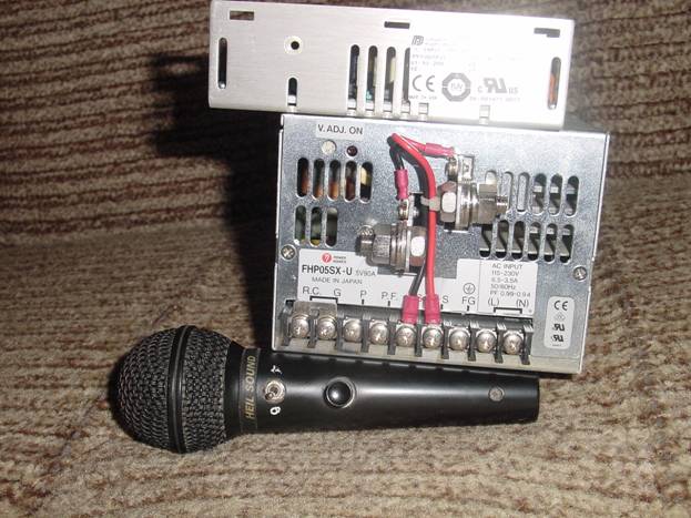
Microphone HEIL SOUND HM-10-5 with two “tablets” (different frequency ranges) is here for an understanding of the dimensions.
This is an industrial 500 watt amp on two MRF-150s I took out ;).

And this is its other side.

It was not possible to quickly find a 1 kW industrial amplifier of the same design, only its radiator fins are three times higher, and the board has two parallel amplification channels with an adder between them at the output.
QUESTIONS???
Part 2. Transistor - 600 W - PA on HF
Thanks to everyone who responded to the article. Even to those who thought that I was a rogue, and this article was nothing more than a “scam” and deception.
Fans. Wonderful article by N. Filenko. UA9XBI here on -, I don’t see any point in quoting and repeating. I can only give some figures for orientation: The average hard drive produces noise (average between the standby state and the search state) at a level of 30-35 dB (decibels). For comparison: a whisper - 10-20 dB, a calm human voice - 50-60 dB, a moving train - 90 dB, a plane taking off - 120 dB, pain threshold - more than 130 dB. As for combat use: office noise (printers, faxes, copiers, etc.) - 50 dB, noise in a living room - 30-40 dB, computer fan noise- 20-34 dB. If you want to buy a normal fan, please: http://www.zifrovoi.ru/catalog/coolers/all/
Photos. It seems that this is precisely where some are trying to find the catch. I ordered and bought the first board in Japan, and I posted these same pictures only because they were made more beautiful on a blue background (I think so). There is no secret to this. But if someone thinks that this is not so, please use the same board (again with my microphone).

Power. Now I will film everything on my sofa J). Here's another mind

The output power by range is written on a piece of paper attached to the board with a wire. The resolution of all photographs is sufficient to allow you to examine everything in great detail. What we see there: in the ranges of 7, 10, 14, 18 MHz it produces 500 watts. You see it says there - with a supply voltage of 28 V and an input power of 10 W on all ranges.
At 3.5 and 21 MHz, respectively – 320 W and 400 W. At 1.9 MHz - 200 watts, 24 MHz - 240 watts, and at 28 MHz 160 watts. Thus, at a level of -3dB (which is half the power), the frequency range of the amplifier is 1.9 – 24 MHz. Doubling the power changes the S-meter signal level by only 0.5 points. At a frequency of 28 MHz, the level of the received signal will drop by 0.7 points. By the way, it should be noted that the antenna opening angle is determined in the same way - at half power level, i.e. at a level of -3dB.
In order to increase the output power by 1.9, 24 and 28 MHz, you simply need to increase the input power by 2-3 times (20-30W). Or make an ALC system - automatic power level control. I didn't do this because... I find it easier to turn the RFPWR knob.
This power is provided by the board you see in the photo. I have no doubt that when powered from a 48 V source, and with design optimization of transformers, this board can deliver “a little more” power. And if you add a couple of such modules, you have 1000 watts. Now think about it, is it worth striving for 2000 watts if, in the end, you get an increase in the signal level at the receiving end of only 0.5 points? An example of my neighbor’s work, I won’t give his call sign. On 20, I receive it at 9+50dB (the S-meter is calibrated), and I hear the second harmonic at 28 MHz at 9+5dB. The person has a good antenna (biggun5 el), but the amplifier... is made impeccably, neatly, beautifully, it tells everyone that I have “two hundred kilos” of honest money. And there are two GMI-11 lamps in parallel and an anode voltage of 2500 volts. How is that? Fine? No amount of persuasion helps. And even though a good engineer himself understands that reducing the level by 0.5 points is nonsense, he does NOTHING.
I have a GU-73P amplifier, cooled with some kind of coolant. And the power supply for it, which I was too lazy to photograph. I have never turned it on (it delivers 2500 watts), the power supply weighs about 50 kg. They wanted to somehow steal it because of the aluminum casing, but they couldn’t lift the hi-hi.
Power supplies. First, a photo of a pulse power supply from a well-known American company

This UPS provides 20 volts and 125 amps, for a total of 2500 watts. Weight – approximately 12-15 kg. When examined on the table of the RZ3CC, it turned out that it was absolutely not suitable for our applications. At the moments of switching key transistors, such pulses jump that it becomes even uninteresting to look for options for protecting the receiver from them. True, it must be said that this was a development approximately 15 years ago, and then, of course, they did not yet know about resonant UPSs. The bottom line is that the operating principle of the converters that are used in power supplies for modern transceivers is not suitable for high powers.
Now let's look at the UPSs that I use.

This is understandable - a computer UPS. For those who said something about high currents - enlarge the picture and see the inscription 5v/50a - no bolts and nuts. What I mean is that nothing prevents you from making a connection, for example, even with a ribbon cable.
There are two UPSs here, the top 5V/20A, the bottom 5V/90A. The progress is noticeable - UPSs have become noticeably smaller and lighter. In the IC-781 500W UPS, the power supply has very small dimensions and weighs about 1.5-2 kg, but it is already more than 15 years old. Agree that technology has come a long way.

A 750 W UPS for a computer already has two 12V/22A windings. Take two of these UPSs and get 48V/22A of power input. Just don't forget to decouple the sources with diodes. If you do a little magic with other voltages of these UPSs, you can get an input power of 1600 watts.
My output stage worked with a traditional transformer power supply, in the photo below you see the bus with which the OSM -1 1.0 is wound, by the way, its price on the Internet is 2930 rubles.

Winding with such a bus does not greatly increase enthusiasm, and the weight of the transformer turns out to be quite considerable.
I have already said that I have a NORMAL attitude towards lamps; they will be out of competition in the industry for a long time. But I still want something more compact and lightweight. It turned out that they do it, although not for a wide audience. At one research institute I was offered a pulse power supply for a tube PA. They said this: 3000v, 1.5a, in a case, with protection, with the highest class of reliability, in a volume of 3 liters, weighing 2-3 kg, all elements are imported (ferrites only Epcos), for 30,000 rubles, for 1 month. I asked if I could see the diagram, the answer was 15,000 rubles, and the diagram with a detailed description is yours. I didn't buy the circuit. But I realized that there are very interesting options for radio amateurs.


This is a kilowatt module on two GI-46Bs. Fans and heatsinks from the processor. The radiator area of each lamp is 850 cm2, which is almost twice as large as that of the “native” radiator. This idea has been stopped in its implementation for now, due to the emergence of an alternative - on transistors.
Scheme. I will give both diagrams that I received.


As I said - nothing unusual - the most standard schemes. The quiescent current of each transistor is 150-250 mA. As for ferrites, I would strongly advise against using our ferrites at all. There is only one reason - instability of parameters. Red has several options for ferrites - choose any one that suits the power and frequency. Output transformers: I have several options - blue ferrites are AmidonFT-23-43, diameter 23mm, material 43, 6 pieces in each column. 4 turns of wire with a cross section of 1.5 mm square. In the second ring amplifier TDKK6a.77.08 the outer diameter is 28mm, the inner diameter is 16mm, the ring height is 8mm. Two rings in each column. Four turns of stranded silver wire, with a cross section of 2-2.5 mm square. Input transformers – rings internal. Diam. 14-16 mm, internal – 8 mm, column length – 14-18 mm, material M600NN. Four turns of wire with a cross section of 0.35 mm square. The dimensions of ferrite rings in transformers depend solely on the power losses. It is for this reason that, with precise matching, the ring sizes can be very small. As an example, the following photo shows a block of bandpass filters from 500 W, ICOM, which was given to me by RZ3CC (G. Shulgin).

Remember to install high voltage ceramic capacitors where they are indicated on the diagram.


Shown here are measurements of output power versus input power. Not my measurements. The first picture is American, the second is Japanese. But the order of power is absolutely obvious, I would say noticeably better than on the GU-74B, and only two 2SC2879. Well, look at the last sign from the Japanese - it’s very characteristic. This is powered by a pair of MRF448pp transistors; according to the datasheet, they have a power of 250 W, but deliver more than 250x2.
Pin (W) Pout (W) Vip (V) Ip (A) Pip (W) Efficiency (%)
1 82 48.3 7 338 24.3 2 177 48.3 12 580 30.5 5 380 47.8 19 908 41.8 10 530 46.5 24 1116 47.5 14 630 46.0 25 1196 52.7
Coordination. I would like to pay special attention to the coordination of the transistor PA with the antenna. Of course, it is best to use an automatic antenna tuner (by the way, someone on the forum decided that I want to cram three times larger variable capacitances and inductances into the same volume. This is a very bold assumption, hi-hi), but it is also necessary to have normal antennas, or at least a hand-held matching device. I don’t understand the statements that a lamp will “keep” a large SWR, unlike a transistor. And at the same time, I am not at all interested in the fact that at the same time all the TVs in the area will go out and not only telephones, but also irons will start talking. But “we work” on Alpha, or on something else, no less than one kilowatt. Protecting a transistor PA is quite simple; I think RK3AQW wrote about it in the forum. I do the same, but I limit the critical SWR not to 10 but to 6. That is, the amplifier output is loaded onto a non-inductive resistor with a resistance of 300 ohms. This is a price to pay for the reliability of the amplifier as a whole. This resistor consists of 2, one is 270 ohms, and the second is a construction carbon 47 ohms. From the engine of this resistor, through a pair of diodes with a capacitor, the voltage is supplied to the base of the transistor switch on 2N2222, in the collector of which there is a RES-49, which with its contacts removes the bias voltage from the output stage. Since SWR=6 transistors can “tolerate” for quite a long time, during this time the bias is completely calmly removed. Well, then - repair or adjustment of the antenna.
1 kW PA
.
And this is the rear view.

From the details side, you can see that there are two channels, two power supplies are connected, and there is an adder. Please note that a piece of cut coaxial cable is visible on the right - the output. I would like to note separately that its diameter is 2.5 mm. I think that for powers of 1000 W or more, our people use cables with an outer diameter of 11-15 mm. Here 2.5 mm will probably cause a storm of anger. But there is an RG-142 cable, the diameter of which with an outer sheath is 4.95 mm, which is capable of transmitting a power of 3.5 kW at a frequency of 50 MHz. And also pay attention to the size of the ferrites - no hint of gigantic size. Etc.

This is a fairly “old” microphone processor, it has a compressor, reverb, some kind of built-in melody, a monitor from the receiver, and a level indicator. The next photo is a modern device with the same purpose.


This is an inexpensive VHF 150W standard PA, which can easily fit a 600W HF PA, although the heat sink is rather weak, but it can be blown out with a cooler or replaced. And the amplifier that is inside can be easily converted to 250 HF watts.

Microphone graphic equalizer. The good thing is that in the 3 kHz band it has 5 bands of active adjustments.

This, for example, is a microphone switch that can switch two different microphones to two different transceivers in any order (HF and VHF, for example).

This is a three-kilowatt coaxial antenna switch with 6 antennas.

This is a TVI filter.

And the time for this miracle, at least for radio amateurs, should be over.
73! RU3BT. Sergey
Hello! I bring to your attention RA on IRF-IRL transistors. I repeated the diagram below. The RA was assembled without modifications. The transistors were not specially selected. I tried three fours: - IRF 510, IRF 540, IRLZ 24N. I was just experimenting, or rather, I was interested in the best power output at 21 and 28 MHz. Everything worked, but if on the low frequency ranges the power was supplied at 120-140 watts, then at 21 MHz it dropped to 80 watts, and at 28 MHz, to 60 watts. The 13.6V power supply was no longer supplied, although these field workers can be powered with two or three times more voltage to revive the “tags” and “tens”. I settled on the IRF 540. The beauty of this RA is that it runs with very little power; -3-5 watts. With a QRP transceiver, it's just a "bomb." The cost is around 100 hryvnia, and maybe even for someone it will be free. But with the pumping power, REMEMBER ALWAYS!!! - no more than 5 watts. Up to the “twenty”, guaranteed 100-120 watts, but what else is needed? “tag” and “ten” may be more powerful for someone, but no less than I claim. The DFT is a separate design, taken from two or maybe three other transistor RAs, I selected based on the available capacitances. I don’t remember which range with which design, but they are all 5th order, tuned IN, -OUT. 50\50 Ohm. How it was done constructively can be seen in the photographs.

The amplifier is assembled using a push-pull circuit using mosfets T1 - T4. The long line type transformer TR1 provides the transition from an asymmetrical excitation source to the symmetrical input of a push-pull cascade.
Resistors R7, R9 allow you to match the input impedance of the cascade with a 50-ohm coaxial line in the range of 1.8-30 MHz.
Their low resistance provides the amplifier with very good resistance to self-excitation. To set the initial offset, use the chain R14, R15, R20, R21.
A circuit of zener diode DZ1 and diodes D1, D2 protects the transistor gates from high voltage surges. Diodes D4, D5 in series with resistors R11, R12 create a small auto bias.
Feedback chains R18, R19. C20, C21 adjusts the frequency response of the amplifier. Capacitor C22 is selected according to the maximum amplitude of the output signal at frequencies of 24-29 MHz.
The TR1 transformer is made on Amidon BN-43-202 binoculars, 2x10 turns of enameled wire with a diameter of 0.35 mm. slightly twisted, about 2 twists per cm.
The TR2 transformer is made on Amidon BN-43-3312 binoculars. The primary winding is one turn of cable braid, inside of which 3 turns of MGTF 1 mm are wound.
FB1, FB2, ferrite beads amidon FB-43-101, which are placed directly on the terminals of resistors R7, R9. as in the diagram.
Choke DR1 is any of the power supply from the computer, which is on a small ferrite rod, usually has 8-15 turns of 1.5 - 2 mm wire. In my case, it was used with 10 turns of 1.5 mm wire. When measured with the device, it showed an inductance of 4.7 μH.
Resistor R14, R15, It is advisable to use multi-turn ones.
Setting the amplifier for quiescent current is simple, but requires attention. We set resistor R15 to the middle position, R14 to the bottom according to the diagram, apply power, connect the PTT contact to minus so that key T5 opens. and five volts of power came to the stabilizer. Without installing transformer TR2, we connect the ampere meter, with a positive probe to the power supply plus, and another (minus) probe, alternately, to one and the other arm of the transistors. By turning the slider of resistor R14 up according to the diagram, we raise the quiescent current to 100 mA. Then, using resistor R15, we achieve identical readings on both arms. And so on until there is 220 Ma on each shoulder.
At this point, setting the quiescent current is completed; you can fix the resistors with varnish or paint so as not to accidentally knock them down.
Many people have radio broadcasting receivers for the medium wave range. But broadcasting on medium waves has now almost ceased in many regions; most radio stations have finally switched to VHF.
It's good if the receiver has a VHF range. If this is an old Soviet receiver on “SV-DV”, then in this case it is of no use at all.
However, not all AM “vanished into oblivion.” There is also a short-wave range, where radio broadcasting is very active, in particular, this is due to the properties of HF waves to propagate over very long distances.
This allows a relatively simple receiver to receive radio stations from almost the entire world.
Converting a medium-wave receiver to short waves is relatively easy, and you don't even need to interfere much with its circuitry. You need to make a converter that converts HF band signals into MF band signals, and send a signal from it to the antenna input of the MF radio receiver.
The figure shows a converter circuit that allows you to receive the HF broadcast band “31 meters” on a standard medium-wave receiver.
Schematic diagram
The converter consists of a frequency converter on a field-effect transistor VT1 and a local oscillator on a field-effect transistor VT2. The converter itself does not have tuning controls; tuning to a station is carried out by the tuning controls of the medium-wave receiver. The input signal from the antenna goes to the input circuit L1-C2.
This circuit is tuned to the middle of the HF range “31 meters” (at a frequency of 9.65 MHz). From it, the signal goes to the gate of the field-effect transistor VT1. Local oscillator on transistor VT2 with quartz frequency stabilization.
Rice. 1. Schematic diagram of a HF converter using KP303 transistors.
The frequency is stabilized by a quartz resonator at 8.86 MHz. There are two reasons for using such a resonator. Firstly, this resonator is used in video technology, and therefore is very common and affordable.
Secondly, with a local oscillator frequency of 8.86 MHz, the scale of a standard receiver with the SW range includes a section of the HF range within the range of 9.38 - 10.48 MHz, which covers the most densely populated HF range “31 meters”, in which there is excellent Very long-distance radio stations are received both during the day and at night (night is still better).
At the output of the frequency converter is inductor L2, from which the signal of the sum and difference frequencies is fed through capacitor C4 to the antenna socket of the SV radio receiver.
If the receiver does not have an antenna jack, one will have to be made by connecting it to its input circuit (to the ungrounded end of the magnetic antenna coil).
Details
List of radio parts for converter assembly:
Transistors KP303 - 2 pcs.
Quartz at 8863 kHz - 1 pc.
Resistor 100k - 1 pc.
Resistor 1K - 1 pc.
Resistor 470 Ohm - 1 pc.
Capacitor 30 pF - 3 pcs.
Capacitor 220 pF - 2 pcs.
Capacitor 0.1 uF - 1 pc.
ferrite ring with a diameter of 7 mm - 1 pc.
![]()
Rice. 2. Pinout and photo of field-effect transistor KP303.
Coil L1 is frameless, diameter 18 mm, contains 14 turns of PEV 0.64 wire (a different cross-section is possible, from 0.5 to 1.0). Coil L2 is wound on a ferrite ring with a diameter of 7 mm.
Contains 200 turns of PEV 0.12 (0.1-0.16 is possible). When setting up the converter, the input circuit is adjusted by stretching and compressing the turns of coil L1.
I present to your attention a power amplifier for a HF transceiver using IRF510 field-effect transistors.
With an input power of about 1 watt, the output is easily 100-150 watts.
I immediately apologize for the quality of the diagram.
The amplifier is two-stage. Both stages are made on popular and cheap key mosfets, which distinguishes this design from many others. The first stage is single-ended. Input matching with a 50 Ohm signal source was achieved not in the best, but simple way - by using a 51 Ohm resistor R4 at the input. The load of the cascade is the primary winding of the interstage matching transformer. The cascade is covered by a negative feedback circuit to equalize the frequency response. L1, which is part of this circuit, reduces the feedback in the higher frequencies and thereby increases the gain. The same goal is pursued by installing C1 in parallel with the resistor at the source of the transistor. The second cascade is push-pull. In order to minimize harmonics, separate displacement of the cascade arms is applied. Each shoulder is also covered by an OOS chain. The load of the cascade is transformer Tr3, and matching and transition to an asymmetric load is provided by Tr2. The bias of each stage and, accordingly, the quiescent current are set separately using trimming resistors. Voltage is supplied to these resistors through the PTT switch on transistor T6. Switching to TX occurs when the PTT point is shorted to ground. The bias voltage is stabilized at 5V by an integrated stabilizer. In general, a very simple scheme with good performance characteristics.
Now about the details. All amplifier transistors are IRF510. Others can be used, but with them you can expect an increase in the gain rolloff in the frequency range above 20 MHz, since the input and pass-through capacitances of the IRF-510 transistors are the lowest of the entire line of key mosfets. If you can find MS-1307 transistors, you can count on a significant improvement in the performance of the amplifier in the higher frequencies. But they are expensive... The inductance of chokes Dr1 and Dr2 is not critical - they are wound on rings of 1000NN ferrite with 0.8 wire in one layer until filled. All capacitors are SMD. Capacitors C5, C6 and especially C14, C15 must have sufficient reactive power. If necessary, you can use several capacitors connected in parallel. To ensure high-quality operation of the amplifier, special attention must be paid to the manufacture of transformers. Tr3 is wound on a 600NN ferrite ring with an outer diameter of 22 mm and contains 2 windings of 7 turns each. It is wound into two wires that are slightly twisted. Wire - PEL-2 0.9.
Tr1 and Tr2 are made according to the classic design of a single-turn SHPT (aka “binoculars”). Tr1 is made on 10 rings (2 pillars of 5 each) made of 1000NN ferrite with a diameter of 12 mm. The windings are made of thick MGTF wire. The first contains 5 turns, the second - 2 turns. Good results are obtained by making windings from several wires of smaller cross-section connected in parallel. Tr2 is made using ferrite tubes taken from the monitor signal cords. Copper tubes are tightly inserted inside their holes, which form one turn - the primary winding. A secondary winding is wound inside, which contains 4 turns and is made of MGTF wire. (7 wires in parallel). This circuit does not have elements to protect the output stage from high SWR, except for built-in structural diodes that effectively protect transistors from “instantaneous” overvoltages at the drains. Protection against SWR is handled by a separate unit, built on the basis of an SWR meter and reducing the supply voltage when the SWR increases above a certain limit. This diagram is the topic of a separate article. Resistors R1-R4,R7-R9,R17,R10,R11 - type MLT-1.R6 - MLT-2. R13,R12 - MLT-0.5. The rest are SMD 0.25 W.