How to build a LAN - a local network for a small enterprise. Principles of operation of a local network Schemes for constructing local computer networks
A local area network unites subscribers located at a short distance from each other (within 10-15 km). Typically, such networks are built within the same enterprise or organization.
Information systems built on the basis of local computer networks provide solutions to the following tasks:
Data storage;
Data processing;
Organizing user access to data;
Transfer of data and the results of their processing to users.
Computer networks implement distributed data processing. Here, data processing is distributed between two entities: the client and the server. During data processing, the client generates a request to the server to perform complex procedures. The server fulfills the request, provides storage of public data, organizes access to this data, and transmits the data to the client. This model of a computer network is called client-server architecture.
Based on the distribution of functions, local computer networks are divided into peer-to-peer and two-rank (hierarchical networks or networks with a dedicated server).
In a peer-to-peer network, computers have equal rights in relation to each other. Each user on the network decides for himself which resources of his computer he will provide for public use. Thus, the computer acts both as a client and as a server. Peer-to-peer sharing of resources is quite acceptable for small offices with 5-10 users, combining them into a work group.
A two-rank network is organized on the basis of a server on which network users register.
For modern computer networks, a mixed network is typical, combining workstations and servers, with some of the workstations forming peer-to-peer networks, and the other part belonging to two-peer networks.
The geometric connection diagram (physical connection configuration) of network nodes is called network topology. There are a large number of network topology options, the basic ones being bus, ring, and star.
Tire. The communication channel connecting nodes into a network forms a broken line - a bus. Any node can receive information at any time, and transmit only when the bus is free. Data (signals) are transmitted by the computer to the bus. Each computer checks them, determining who the information is addressed to, and accepts the data if it is sent to it, or ignores it.
With a bus topology, the information transmission medium is represented in the form of a communication path accessible to all workstations, to which they all must be connected. All workstations can communicate directly with any workstation on the network. If computers are located close to each other, then organizing a computer network with a bus topology is inexpensive and simple - you just need to lay a cable from one computer to another. Signal attenuation with increasing distance limits the length of the bus and, therefore, the number of computers connected to it.
Workstations can be connected to or disconnected from it at any time, without interrupting the operation of the entire computer network. The functioning of a computer network does not depend on the state of an individual workstation.
Ring. The nodes are connected into a closed curve network. The workstation sends information to a specific destination address, having previously received a request from the ring. Data transfer is carried out in one direction only. Each node, among other things, implements the functions of a repeater. He receives and transmits messages, and perceives only those addressed to him. Using a ring topology, you can connect a large number of nodes to the network, solving the problems of interference and signal attenuation using the network card of each node. Message forwarding is very efficient since most messages can be sent “on the road” over the cable system one after another. It is very easy to make a ring request to all stations. The duration of information transfer increases in proportion to the number of workstations included in the computer network.
With a ring network topology, workstations are connected to one another in a circle, i.e. workstation 1 with workstation 2, workstation 3 with workstation 4, etc. The last workstation is connected to the first. The communication link is closed in a ring. Laying cables from one workstation to another can be quite complex and expensive, especially if the workstations are geographically located far from the ring (for example, in a line).
The main problem with a ring topology is that each workstation must actively participate in the transfer of information, and if at least one of them fails, the entire network is paralyzed. Faults in cable connections are easily localized.
Connecting a new workstation requires a short-term shutdown of the network, since the ring must be open during installation. There is no limit on the length of a computer network, since it is ultimately determined solely by the distance between two workstations.
Star. The network nodes are connected to the center by rays. All information is transmitted through the center, making it relatively easy to troubleshoot and add new nodes without interrupting the network. However, the cost of organizing communication channels here is usually higher than for a bus and ring.
The concept of a star network topology comes from the field of mainframe computers, in which the head machine receives and processes all data from peripheral devices as the active processing node. This principle is used in data communication systems, such as RELCOM e-mail. All information between two peripheral workstations passes through the central node of the computer network.
Network throughput is determined by the computing power of the node and is guaranteed for each workstation. There are no data collisions.
Local area network is a concept that is familiar to many firsthand. Almost every enterprise uses this technology, so it can be said that every person has come across it in one way or another. Local networks have significantly accelerated production processes, thereby giving a sharp boost to their further use throughout the globe. All this allows us to predict the further growth and development of such a data transmission system, up to the introduction of a LAN in every, even the smallest enterprise.
The concept of a local network
A local area network is a number of computers connected to each other by special equipment that allows for the full exchange of information between them. An important feature of this type of data transmission is the relatively small area where communication nodes, that is, the computers themselves, are located.
Local networks not only greatly facilitate interaction between users, but also perform some other functions:
- Simplify work with documentation. Employees can edit and view files at their workplace. At the same time, there is no need for collective meetings and meetings, which saves valuable time.
- They allow you to work on documents together with colleagues, when everyone is at their own computer.
- They allow access to applications installed on the server, which allows you to save free space on the installed hard drive.
- Save hard drive space by allowing you to save documents on your host computer.
Types of networks
A local area network can be represented by two models: a peer-to-peer network and a hierarchical one. They differ in the ways communication nodes interact.
A peer-to-peer network is based on the equality of all machines, and data is distributed between each of them. Essentially, a user of one computer can access the resources and information of another. The efficiency of the peer-to-peer model directly depends on the number of worker nodes, and its level of security is unsatisfactory, which, coupled with a rather complex management process, makes such networks not very reliable and convenient.

The hierarchical model includes one (or more) main server, where all data is stored and processed, and several client nodes. This type of network is used much more often than the first, having the advantage of speed, reliability and security. However, the speed of such a LAN largely depends on the server, which under certain conditions can be considered a disadvantage.
Drawing up technical requirements
Designing a local area network is a rather complex process. It begins with the development of a technical specification, which should be carefully considered, since shortcomings in it threaten subsequent difficulties in building a network and additional financial costs. Primary design can be done using special configurators that will allow you to select the optimal network equipment. Such programs are especially convenient in that you can correct various values and parameters directly during operation, as well as generate a report at the end of the process. Only after these steps can you proceed to the next stage.
Schematic design
This stage consists of collecting data about the enterprise where it is planned to install a local area network, and analyzing the information received. The quantity is determined:
- Users.
- Workstations.
- Server rooms.
- Connection ports.

An important point is the availability of data on the routes for laying highways and the planning of a specific topology. In general, it is necessary to adhere to a number of requirements imposed by the IEEE 802.3 standard. However, despite these rules, sometimes it may be necessary to make calculations of signal propagation delays or consult with network equipment manufacturers.
Basic LAN characteristics
When choosing a method for placing communication nodes, you must remember the basic requirements for local networks:
- Performance, which combines several concepts: throughput, response time, transmission delay.
- Compatibility, i.e. ability to connect various local area network equipment and software.
- Safety, reliability, i.e. capabilities to prevent unauthorized access and complete data protection.
- Scalability - the ability to increase the number of workstations without degrading network performance.
- Manageability - the ability to control the main elements of the network, prevent and eliminate problems.
- Network transparency, which consists of presenting a single computing device to users.
Basic local area network topologies: advantages and disadvantages
The topology of a network represents its physical layout, significantly affecting its basic characteristics. In modern enterprises, three types of topologies are mainly used: “Star”, “Bus” and “Ring”.

The “Star” topology is the most common and has many advantages over others. This installation method is highly reliable; If any computer fails (except the server), this will not affect the operation of the others.
The “Bus” topology is a single backbone cable with connected computers. Such an organization of a local area network saves money, but is not suitable for connecting a large number of computers.
The “Ring” topology is characterized by low reliability due to the special arrangement of nodes - each of them is connected to two others using network cards. The failure of one computer leads to the shutdown of the entire network, so this type of topology is used less and less.
Detailed network design
An enterprise local area network also includes various technologies, equipment and cables. Therefore, the next step will be the selection of all these elements. Making a decision in favor of one or another software or hardware is determined by the purpose of creating the network, the number of users, the list of programs used, the size of the network, and its location. Currently, fiber optic highways are most often used, which are distinguished by their high reliability, speed and availability.
About cable types
Cables are used in networks to transmit signals between workstations; each of them has its own characteristics, which must be taken into account when designing a LAN.

- A twisted pair consists of several pairs of conductors covered with insulation and twisted together. Low price and ease of installation are beneficial advantages, which makes this cable the most popular for installing local networks.
- A coaxial cable consists of two conductors inserted one inside the other. A local area network using coax is no longer so common - it was replaced by twisted pair, but it is still found in some places.
- Optical fiber is a glass thread that can carry light by reflecting it off walls. A cable made from this material transmits data over long distances and is fast compared to twisted pair and coaxial cables, but it is not cheap.
Necessary equipment
Network equipment of local area networks includes many elements, the most commonly used of which are:

- Hub or hub. It connects a number of devices into one segment using a cable.
- Switch. Uses special processors for each port, processing packets separately from other ports, due to which they have high performance.
- Router. This is a device that makes decisions about sending packets based on data about routing tables and some rules.
- Modem. Widely used in communication systems, providing contact with other workstations via a cable or telephone network.
End network equipment
The local area network hardware necessarily includes server and client parts.
A server is a powerful computer with high network significance. Its functions include storing information, databases, serving users and processing program codes. The servers are located in special rooms with a controlled constant air temperature - server rooms, and their housing is equipped with additional protection from dust, accidental shutdown, as well as a powerful cooling system. As a rule, only system administrators or company managers have access to the server.

A workstation is a regular computer connected to a network, that is, it is any computer that requests services from the main server. To ensure communication at such nodes, a modem and a network card are used. Since workstations usually use server resources, the client part is equipped with weak memory sticks and small hard drives.
Software
Local area network equipment will not be able to fully perform its functions without suitable software. The software part includes:
- Network operating systems on servers that form the basis of any network. It is the OS that controls access to all network resources, coordinates packet routing, and resolves device conflicts. Such systems have built-in support for the TCP/IP, NetBEUI, IPX/SPX protocols.
- Autonomous operating systems that manage the client side. They are common operating systems, for example, Windows XP, Windows 7.
- Network services and applications. These software elements allow you to perform various actions: viewing remote documentation, printing on a network printer, sending email messages. Traditional services HTTP, POP-3, SMTP, FTP and Telnet are the basis of this category and are implemented using software.
Nuances of designing local networks
Designing a local area network requires a long and leisurely analysis, as well as taking into account all the subtleties. It is important to provide for the possibility of enterprise growth, which will entail an increase in the scale of the local network. The project must be drawn up in such a way that the LAN is ready at any time to connect a new workstation or other device, as well as upgrade any of its nodes and components.
Security issues are no less important. The cables used to build the network must be reliably protected from unauthorized access, and the lines must be located away from potentially dangerous places where they can be damaged - accidentally or intentionally. LAN components located outside the premises must be grounded and securely secured.
Developing a local area network is a fairly labor-intensive process, but with the right approach and due responsibility, the LAN will operate reliably and stably, ensuring uninterrupted user experience.
Moscow State Mining University
Department of Automated Control Systems
Course project
in the discipline "Computer networks and telecommunications"
on the topic: “Design of a local area network”
Completed:
Art. gr. AS-1-06
Yuryeva Ya.G.
Checked:
Prof., Doctor of Technical Sciences Shek V.M.
Moscow 2009
Introduction
1 Design task
2 Description of the local area network
3 Network topology
4 Local network diagram
5 OSI reference model
6 Justification for choosing a local network deployment technology
7 Network protocols
8 Hardware and software
9 Calculation of network characteristics
Bibliography
A local area network (LAN) is a communications system that connects computers and peripheral equipment in a limited area, usually no more than several buildings or one enterprise. Currently, a LAN has become an integral attribute in any computing systems with more than 1 computer.
The main advantages provided by a local network are the ability to collaborate and quickly exchange data, centralized data storage, shared access to shared resources such as printers, the Internet and others.
Another important function of a local network is the creation of fault-tolerant systems that continue to function (albeit not fully) if some of their elements fail. In a LAN, fault tolerance is ensured through redundancy and duplication; as well as flexibility in the operation of individual parts (computers) included in the network.
The ultimate goal of creating a local network in an enterprise or organization is to increase the efficiency of the computing system as a whole.
Building a reliable LAN that meets your performance requirements and has the lowest cost requires starting with a plan. In the plan, the network is divided into segments, and a suitable topology and hardware are selected.
The bus topology is often called a linear bus. This topology is one of the simplest and most widespread topologies. It uses a single cable, called a backbone or segment, along which all computers on the network are connected.
In a network with a “bus” topology (Fig. 1.), computers address data to a specific computer, transmitting it over a cable in the form of electrical signals.

Fig.1. Bus topology
Data in the form of electrical signals is transmitted to all computers on the network; however, only the one whose address matches the recipient address encrypted in these signals receives information. Moreover, at any given time, only one computer can transmit.
Since data is transmitted to the network by only one computer, its performance depends on the number of computers connected to the bus. The more there are, i.e. The more computers waiting to transfer data, the slower the network.
However, it is impossible to derive a direct relationship between network bandwidth and the number of computers in it. Since, in addition to the number of computers, network performance is influenced by many factors, including:
· hardware characteristics of computers on the network;
· the frequency with which computers transmit data;
· type of running network applications;
· type of network cable;
· distance between computers on the network.
The bus is a passive topology. This means that computers only “listen” to data transmitted over the network, but do not move it from sender to recipient. Therefore, if one of the computers fails, it will not affect the operation of the others. In active topologies, computers regenerate signals and transmit them across the network.
Signal reflection
Data, or electrical signals, travel throughout the network - from one end of the cable to the other. If no special action is taken, the signal reaching the end of the cable will be reflected and will not allow other computers to transmit. Therefore, after the data reaches the destination, the electrical signals must be extinguished.
Terminator
To prevent electrical signals from being reflected, terminators are installed at each end of the cable to absorb these signals. All ends of the network cable must be connected to something, such as a computer or a barrel connector - to increase the cable length. A terminator must be connected to any free - unconnected - end of the cable to prevent electrical signals from being reflected.
Network integrity violation
A network cable breaks when it is physically broken or one of its ends is disconnected. It is also possible that there are no terminators at one or more ends of the cable, which leads to reflection of electrical signals in the cable and termination of the network. The network is falling.
The computers themselves on the network remain fully functional, but as long as the segment is broken, they cannot communicate with each other.
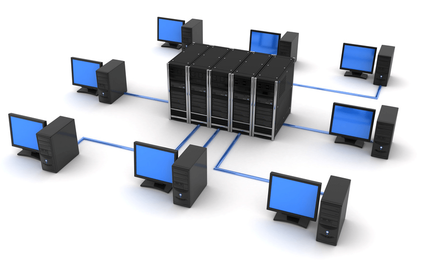
The concept of a star network topology (Fig. 2.) comes from the field of mainframe computers, in which the head machine receives and processes all data from peripheral devices as an active data processing node. This principle is applied in data transmission systems. All information between two peripheral workstations passes through the central node of the computer network.

Fig.2. Star topology
Network throughput is determined by the computing power of the node and is guaranteed for each workstation. There are no data collisions. Cabling is quite simple as each workstation is connected to a node. Cabling costs are high, especially when the central node is not geographically located in the center of the topology.
When expanding computer networks, previously made cable connections cannot be used: a separate cable must be laid from the center of the network to the new workplace.
The star topology is the fastest of all computer network topologies because data transfer between workstations passes through a central node (if its performance is good) over separate lines used only by these workstations. The frequency of requests to transfer information from one station to another is low compared to that achieved in other topologies.
The performance of a computer network primarily depends on the power of the central file server. It can be a bottleneck in the computer network. If the central node fails, the entire network is disrupted. The central control node - the file server - implements the optimal protection mechanism against unauthorized access to information. The entire computer network can be controlled from its center.
Advantages
· Failure of one workstation does not affect the operation of the entire network as a whole;
· Good network scalability;
· Easy search for faults and breaks in the network;
· High network performance;
· Flexible administration options.
Flaws
· Failure of the central hub will result in the inoperability of the network as a whole;
· Laying a network often requires more cable than most other topologies;
· A finite number of workstations, i.e. the number of workstations is limited by the number of ports in the central hub.
With a ring topology (Fig. 3.) of the network, workstations are connected to one another in a circle, i.e. workstation 1 with workstation 2, workstation 3 with workstation 4, etc. The last workstation is connected to the first. The communication link is closed in a ring.

Fig.3. Ring topology
Laying cables from one workstation to another can be quite complex and expensive, especially if the geographical location of the workstations is far from the ring shape (for example, in a line). Messages circulate regularly in circles. The workstation sends information to a specific destination address, having previously received a request from the ring. Message forwarding is very efficient since most messages can be sent "on the road" over the cable system one after another. It is very easy to make a ring request to all stations.
The duration of information transfer increases in proportion to the number of workstations included in the computer network.
The main problem with a ring topology is that each workstation must actively participate in the transfer of information, and if at least one of them fails, the entire network is paralyzed. Faults in cable connections are easily localized.
Connecting a new workstation requires a short-term shutdown of the network, since the ring must be open during installation. There is no limit on the length of a computer network, since it is ultimately determined solely by the distance between two workstations. A special form of ring topology is a logical ring network. Physically, it is mounted as a connection of star topologies.
Individual stars are switched on using special switches (English Hub – concentrator), which in Russian are also sometimes called “hub”.
When creating global (WAN) and regional (MAN) networks, the MESH mesh topology is most often used (Fig. 4.). Initially, this topology was created for telephone networks. Each node in such a network performs the functions of receiving, routing and transmitting data. This topology is very reliable (if any segment fails, there is a route along which data can be transferred to a given node) and is highly resistant to network congestion (a route that is least congested with data transmission can always be found).

Fig.4. Mesh topology.
When developing the network, the “star” topology was chosen due to its simple implementation and high reliability (a separate cable goes to each computer).
1) FastEthernet using 2 switches (Fig. 5)
|
|

Rice. 6. FastEthernet topology using 1 router and 2 switches.
4Local network diagram
Below is a diagram of the location of computers and cable routing on floors (Fig. 7, 8).

Rice. 7. Layout of computers and cable routing on the 1st floor.

Rice. 8. Layout of computers and cable routing on the 2nd floor.
This scheme was developed taking into account the characteristic features of the building. The cables will be located under the artificial flooring, in channels specially designated for them. The cable will be pulled to the second floor through a telecommunications cabinet, which is located in the utility room, which is used as a server room where the server and router are located. Switches are located in the main rooms in cabinets.
Layers interact top-down and bottom-up through interfaces and can also interact with the same layer of another system using protocols.
The protocols used at each layer of the OSI model are presented in Table 1.
Table 1.
Protocols of the OSI model layers
| OSI layer | Protocols |
| Applied | HTTP, gopher, Telnet, DNS, SMTP, SNMP, CMIP, FTP, TFTP, SSH, IRC, AIM, NFS, NNTP, NTP, SNTP, XMPP, FTAM, APPC, X.400, X.500, AFP, LDAP, SIP, ITMS, ModbusTCP, BACnetIP, IMAP, POP3, SMB, MFTP, BitTorrent, eD2k, PROFIBUS |
| Representation | HTTP, ASN.1, XML-RPC, TDI, XDR, SNMP, FTP, Telnet, SMTP, NCP, AFP |
| Session | ASP, ADSP, DLC, Named Pipes, NBT, NetBIOS, NWLink, Printer Access Protocol, Zone Information Protocol, SSL, TLS, SOCKS |
| Transport | TCP, UDP, NetBEUI, AEP, ATP, IL, NBP, RTMP, SMB, SPX, SCTP, DCCP, RTP, TFTP |
| Network | IP, IPv6, ICMP, IGMP, IPX, NWLink, NetBEUI, DDP, IPSec, ARP, RARP, DHCP, BootP, SKIP, RIP |
| Duct | STP, ARCnet, ATM, DTM, SLIP, SMDS, Ethernet, FDDI, Frame Relay, LocalTalk, Token ring, StarLan, L2F, L2TP, PPTP, PPP, PPPoE, PROFIBUS |
| Physical | RS-232, RS-422, RS-423, RS-449, RS-485, ITU-T, xDSL, ISDN, T-carrier (T1, E1), Ethernet standard modifications: 10BASE-T, 10BASE2, 10BASE5, 100BASE- T (includes 100BASE-TX, 100BASE-T4, 100BASE-FX), 1000BASE-T, 1000BASE-TX, 1000BASE-SX |
It should be understood that the vast majority of modern networks, for historical reasons, only roughly correspond in general terms to the ISO/OSI reference model.
The actual OSI protocol stack developed as part of the project was perceived by many as too complex and virtually unimplementable. It involved the abolition of all existing protocols and their replacement with new ones at all levels of the stack. This made the stack very difficult to implement and was the reason for its abandonment by many vendors and users who had made significant investments in other networking technologies. In addition, the OSI protocols were developed by committees that proposed different and sometimes conflicting characteristics, leading to many parameters and features being declared optional. Because too much was optional or left to the developer's choice, different vendors' implementations simply could not interoperate, thus defeating the very idea of the OSI design.
As a result, OSI's attempt to agree on common standards for networking was supplanted by the TCP/IP protocol stack used on the Internet and its simpler, more pragmatic approach to computer networking. The Internet's approach was to create simple protocols with two independent implementations required for a protocol to be considered a standard. This confirmed the practical feasibility of the standard. For example, the definitions of the X.400 email standards consist of several large volumes, and the definition of Internet mail (SMTP) is only a few dozen pages in RFC 821. However, it is worth noting that there are numerous RFCs that define extensions to SMTP. Therefore, at the moment, complete documentation on SMTP and extensions also takes up several large books.
Most protocols and specifications in the OSI stack are no longer in use, such as X.400 email. Only a few survived, often in greatly simplified form. The X.500 directory structure is still in use today, largely due to the simplification of the original cumbersome DAP protocol, which became known as LDAP and became an Internet standard.
The collapse of the OSI project in 1996 dealt a serious blow to the reputation and legitimacy of the organizations involved, especially the ISO. The biggest omission of the OSI creators was their failure to see and acknowledge the superiority of the TCP/IP protocol stack.
To select a technology, consider a table comparing FDDI, Ethernet and TokenRing technologies (Table 2).
Table 2. Characteristics of FDDI, Ethernet, TokenRing technologies
| Characteristic | FDDI | Ethernet | Token Ring |
| Bit speed, Mbit/s | 100 | 10 | 16 |
| Topology | Double ring of trees | Tire/star | Star/ring |
| Data transmission medium | Fiber Optic, Category 5 UTP | Thick coax, thin coax, |
Shielded or unshielded twisted pair, fiber optic |
| Maximum network length (without bridges) |
(100 km per ring) |
2500 m | 40000 m |
| Maximum distance between nodes | 2 km (no more than 11 dB of loss between nodes) | 2500 m | 100 m |
| Maximum number of nodes |
(1000 connections) |
1024 | 260 for shielded twisted pair, 72 for unshielded twisted pair |
After analyzing the table of characteristics of FDDI, Ethernet, TokenRing technologies, the choice of Ethernet technology (or rather its modification FastEthernet), which takes into account all the requirements of our local network, is obvious. Since TokenRing technology provides data transfer speeds of up to 16 Mbit/s, we exclude it from further consideration, and due to the complexity of implementing FDDI technology, it would be most reasonable to use Ethernet.
7Network protocols
The seven-layer OSI model is theoretical and contains a number of shortcomings. Real network protocols have to deviate from it, providing unintended capabilities, so the binding of some of them to OSI layers is somewhat arbitrary.
The main flaw of OSI is the ill-conceived transport layer. On it, OSI allows data exchange between applications (introducing the concept of port - application identifier), however, the ability to exchange simple datagrams in OSI is not provided - the transport layer must form connections, ensure delivery, control the flow, etc. Real protocols implement this possibility .
Network transport protocols provide the basic functionality that computers need to communicate with a network. Such protocols implement complete, efficient communication channels between computers.
The transport protocol can be thought of as a registered mail service. The transport protocol ensures that the transmitted data reaches the specified destination by checking the receipt received from it. It performs monitoring and error correction without higher level intervention.
The main network protocols are:
NWLink IPX/SPX/NetBIOS Compatible Transport Protocol (NWLink) is Novell's NDIS-compatible 32-bit implementation of the IPX/SPX protocol. The NWLink protocol supports two application programming interfaces (APIs): NetBIOS and Windows Sockets. These interfaces allow computers running Windows to communicate with each other, as well as with NetWare servers.
The NWLink transport driver is an implementation of NetWare low-level protocols such as IPX, SPX, RIPX (Routing Information Protocol over IPX) and NBIPX (NetBIOS over IPX). The IPX protocol controls the addressing and routing of data packets within and between networks. The SPX protocol ensures reliable delivery of data by maintaining the correct transmission sequence and acknowledgment mechanism. The NWLink protocol provides NetBIOS compatibility by building a NetBIOS layer on top of the IPX protocol.
IPX/SPX (from the English Internetwork Packet eXchange/Sequenced Packet eXchange) is a protocol stack used in Novell NetWare networks. The IPX protocol provides the network layer (packet delivery, an analogue of IP), SPX - the transport and session layer (an analogue of TCP).
The IPX protocol is designed to transport datagrams on connectionless systems (much like IP or NETBIOS, developed by IBM and emulated by Novell), and provides communications between NetWare servers and end stations.
SPX (Sequence Packet eXchange) and its improved modification SPX II are transport protocols of the ISO 7-layer model. This protocol guarantees packet delivery and uses a sliding window technique (a distant analogue of the TCP protocol). In case of loss or error, the packet is resent, the number of repetitions is set programmatically.
NetBEUI is a protocol that complements the NetBIOS interface specification used by the network operating system. NetBEUI formalizes a transport layer frame that is not standardized in NetBIOS. It does not correspond to any specific layer of the OSI model, but covers the transport layer, network layer and LLC sublayer of the data link layer. NetBEUI interacts directly with NDIS at the MAC level. Thus, it is not a routable protocol.
The transport part of NetBEUI is NBF (NetBIOS Frame protocol). Nowadays, NBT (NetBIOS over TCP/IP) is usually used instead of NetBEUI.
As a rule, NetBEUI is used in networks where it is not possible to use NetBIOS, for example, on computers with MS-DOS installed.
Repeater(English repeater) - designed to increase the distance of a network connection by repeating the electrical signal “one to one”. There are single-port repeaters and multi-port repeaters. In twisted pair networks, a repeater is the cheapest means of combining end nodes and other communications devices into a single shared segment. Ethernet repeaters can have a speed of 10 or 100 Mbit/s (FastEthernet), the same for all ports. Repeaters are not used for GigabitEthernet.
Bridge(from the English bridge - bridge) is a means of transmitting frames between two (or more) logically heterogeneous segments. According to the logic of operation, it is a special case of a switch. The speed is usually 10 Mbit/s (switches are more often used for FastEthernet).
Hub or hub(from the English hub - activity center) - a network device for combining several Ethernet devices into a common segment. Devices are connected using twisted pair, coaxial cable or optical fiber. A hub is a special case of a concentrator
The hub operates at the physical layer of the OSI network model and repeats the signal arriving at one port to all active ports. If a signal arrives on two or more ports at the same time, a collision occurs and the transmitted data frames are lost. This way, all devices connected to the hub are in the same collision domain. Hubs always operate in half-duplex mode; all connected Ethernet devices share the available access bandwidth.
Many hub models have simple protection against an excessive number of collisions arising due to one of the connected devices. In this case, they can isolate the port from the general transmission medium. For this reason, network segments based on twisted pair are much more stable than segments on a coaxial cable, since in the first case each device can be isolated from the general environment by a hub, and in the second case, several devices are connected using one cable segment, and, in In case of a large number of collisions, the hub can only isolate the entire segment.
Recently, hubs have been used quite rarely; instead, switches have become widespread - devices that operate at the data link level of the OSI model and increase network performance by logically separating each connected device into a separate segment, a collision domain.
Switch or switch(from English - switch) Switch (switching hub) According to the principle of frame processing, it is no different from a bridge. Its main difference from a bridge is that it is a kind of communication multiprocessor, since each of its ports is equipped with a specialized processor that processes frames using the bridge algorithm regardless of the processors of other ports. Due to this, the overall performance of the switch is usually much higher than that of a traditional bridge with a single processing unit. We can say that switches are new generation bridges that process frames in parallel.
This is a device designed to connect several computer network nodes within one segment. Unlike a hub, which distributes traffic from one connected device to all others, a switch transmits data only directly to the recipient. This improves network performance and security by freeing other network segments from having to (and being able to) process data that was not intended for them.
The switch operates at the data link layer of the OSI model, and therefore, in general, can only unite hosts of the same network by their MAC addresses. Routers are used to connect multiple networks based on the network layer.
The switch stores a special table in memory (ARP table), which indicates the correspondence of the host MAC address to the switch port. When the switch is turned on, this table is empty and the switch is in learning mode. In this mode, data arriving on any port is transmitted to all other ports of the switch. In this case, the switch analyzes data packets, determining the MAC address of the sending computer, and enters it into a table. Subsequently, if a packet destined for that computer arrives on one of the switch ports, that packet will be sent only to the corresponding port. Over time, the switch builds a complete table for all its ports, and as a result, the traffic is localized.
Switches are divided into managed and unmanaged (the simplest). More complex switches allow you to manage switching at the data link and network levels of the OSI model. They are usually called accordingly, for example Level 2 Switch or simply abbreviated L2. The switch can be managed via Web interface protocol, SNMP, RMON (a protocol developed by Cisco), etc. Many managed switches allow you to perform additional functions: VLAN, QoS, aggregation, mirroring. Complex switches can be combined into one logical device - a stack, in order to increase the number of ports (for example, you can combine 4 switches with 24 ports and get a logical switch with 96 ports).
Interface converter or converter(English mediaconverter) allows you to make transitions from one transmission medium to another (for example, from twisted pair to optical fiber) without logical signal conversion. By amplifying the signals, these devices can overcome limitations on the length of communication lines (if the restrictions are not related to propagation delay). Used to connect equipment with different types of ports.
Three types of converters are available:
× RS-232 converter<–>RS-485;
× USB Converter<–>RS-485;
× Ethernet Converter<–>RS-485.
RS-232 converter<–>RS-485 converts the physical parameters of the RS-232 interface into RS-485 interface signals. Can operate in three reception and transmission modes. (Depending on the software installed in the converter and the state of the switches on the converter board).
USB converter<–>RS-485 - this converter is designed to organize an RS-485 interface on any computer that has a USB interface. The converter is made in the form of a separate board connected to the USB connector. The converter is powered directly from the USB port. The converter driver allows you to create a virtual COM port for the USB interface and work with it as with a regular RS-485 port (similar to RS-232). The device is detected immediately when connected to the USB port.
Ethernet Converter<–>RS-485 - this converter is designed to provide the ability to transmit RS-485 interface signals over a local network. The converter has its own IP address (set by the user) and allows access to the RS-485 interface from any computer connected to the local network and with the appropriate software installed. To work with the converter, 2 programs are supplied: Port Redirector – support for the RS-485 interface (COM port) at the network card level and the Lantronix configurator, which allows you to bind the converter to the user’s local network, as well as set the parameters of the RS-485 interface (baud rate, number of data bits, etc.) The converter provides completely transparent data reception and transmission in any direction.
Router or router(from the English router) is a network device used in computer data networks, which, based on information about the network topology (routing table) and certain rules, makes decisions about forwarding network layer packets of the OSI model to their recipient. Typically used to connect multiple network segments.
Traditionally, a router uses the routing table and the destination address found in the data packets to forward the data. By extracting this information, it determines from the routing table the path along which the data should be transmitted and routes the packet along this route. If there is no described route in the routing table for an address, the packet is discarded.
There are other ways to determine the forwarding route of packets using, for example, the source address, the upper layer protocols used, and other information contained in the network layer packet headers. Often, routers can translate source and recipient addresses (NAT, Network Address Translation), filter the transit data stream based on certain rules to limit access, encrypt/decrypt transmitted data, etc.
Routers help reduce network congestion by dividing it into collision and broadcast domains, as well as packet filtering. They are mainly used to combine networks of different types, often incompatible in architecture and protocols, for example, to combine Ethernet local networks and WAN connections using DSL, PPP, ATM, Frame relay, etc. protocols. A router is often used to provide access from local network to the global Internet, performing the functions of address translation and firewall.
A router can be either a specialized device or a PC computer that performs the functions of a simple router.
Modem(an abbreviation made up of words mo duulator- dem odulator) is a device used in communication systems and performing the function of modulation and demodulation. A special case of a modem is a widely used peripheral device for a computer that allows it to communicate with another computer equipped with a modem through a telephone network (telephone modem) or a cable network (cable modem).
The end network equipment is the source and recipient of information transmitted over the network.
Computer (workstation), connected to the network, is the most versatile node. The applied use of a computer on a network is determined by the software and installed additional equipment. For long-distance communications, a modem is used, internal or external. From a networking point of view, the “face” of a computer is its network adapter. The type of network adapter must match the purpose of the computer and its network activity.
Server is also a computer, but with more resources. This implies its higher network activity and importance. It is advisable to connect servers to a dedicated switch port. When installing two or more network interfaces (including a modem connection) and the corresponding software, the server can play the role of a router or bridge. Servers generally need to have a high-performance operating system.
Table 5 shows the parameters of a typical workstation and its cost for the local network being developed.
Table 5.
Work station
 |
System unit.GH301EA HP dc5750 uMT A64 X2-4200+(2.2GHz),1GB,160GB,ATI Radeon X300,DVD+/-RW,Vista Business | |||||||
| Hewlett-Packard GH301EA dc 5750 series computer. This system unit is equipped with an AMD Athlon™ 64 X2 4200+ processor with a frequency of 2.2 GHz, 1024 MB of DDR2 RAM, a 160 GB hard drive, a DVD-RW drive and Windows Vista Business installed. | ||||||||
| Price: RUB 16,450.00 | ||||||||
 |
Monitor. TFT 19 “Asus V W1935 | |||||||
| Price: 6,000.00 rub. | ||||||||
| Input Devices | ||||||||
| Mouse | Genius GM-03003 | 172 rub. | ||||||
| Keyboard | 208 rub. | |||||||
| total cost | RUB 22,830 | |||||||
Table 6 shows the server parameters.
Table 6.
Server
 |
DESTEN System unit DESTEN eStudio 1024QM | |||||
| Processor INTEL Core 2 Quad Q6600 2.4GHz 1066MHz 8Mb LGA775 OEM Motherboard Gigabyte GA-P35-DS3R ATX Memory module DDR-RAM2 1Gb 667Mhz Kingston KVR667D2N5/1G - 2 Hard drive 250 Gb Hitachi Deskstar T7K500 HDP725 025GLA380 7200RPM 8Mb SATA-2 - 2 Video adapter 512MB Zotac PCI -E 8600GT DDR2 128 bit DVI (ZT-86TEG2P-FSR) DVD drive RW NEC AD-7200S-0B SATA Black ZALMAN HD160XT BLACK housing. | ||||||
| Price: RUB 50,882.00 | ||||||
 |
Monitor. TFT 19 “Asus V W1935 |
|||||
| Type: LCD LCD technology: TN Diagonal: 19" Screen format: 5:4 Max resolution: 1280 x 1024 Inputs: VGA Vertical scan: 75 Hz Horizontal scan: 81 KHz | ||||||
| Price: 6,000.00 rub. | ||||||
| Input Devices | ||||||
| Mouse | Genius GM-03003 | 172 rub. | ||||
| Keyboard | Logitech Value Sea Gray (refresh) PS/2 | 208 rub. | ||||
| total cost | RUB 57,262 | |||||
The server software includes:
× Operating system WindowsServer 2003 SP2+R2
× ABBY FineReader Corporate Edition v8.0 (server license)
× Network administration program SymantecpcAnywhere 12 (server)
Workstation software includes:
× Operating system WindowsXPSP2
× Antivirus program NOD 32 AntiVirusSystem.
× Microsoft Office 2003 (pro)
× ABBY FineReader Corporate Edition v8.0 software package (client license)
× Network administration program Symantec pcAnywhere 12 (client)
× User programs
For real networks, an important performance indicator is network utilization, which is a percentage of the total bandwidth (not divided between individual subscribers). It takes into account collisions and other factors. Neither the server nor the workstations contain tools for determining network usage; special hardware and software tools such as protocol analyzers are designed for this, not always available due to the high cost.
For busy Ethernet and FastEthernet systems, 30% network utilization is considered a good value. This value corresponds to the absence of long-term downtime in the network and provides sufficient reserve in case of peak load increases. However, if the network utilization rate is 80...90% or more for a significant time, then this indicates that the resources are almost completely used (at a given time), but does not leave a reserve for the future.
To carry out calculations and conclusions, you should calculate the performance in each network segment.
Let's calculate the payload Pп:
where n is the number of segments of the designed network.
P0 = 2*16 = 32Mbit/s
The total actual load Pf is calculated taking into account collisions and the magnitude of access delays to the data transmission medium:
| (3) |
where k is the access delay to the data transmission medium: for the Ethernet family of technologies – 0.4, for TokenRing – 0.6, for FDDI – 0.7.
RF = 32*(1+0.4) = 44.8 Mbit/s
Since the actual load Pf > 10 Mbit/s, then, as previously assumed, this network cannot be implemented using the Ethernet standard; it is necessary to use FastEthernet technology (100 Mbit/s).
Because Given that we do not use hubs in the network, there is no need to calculate the double signal turnaround time. (There is no collision signal)
Table 7 shows the final calculation of the cost of a network built on 2 switches. ( Option 1).
Table 6.
Table 8 shows the final calculation of the cost of a network built on 2 switches and 1 router. ( Option 2).
Table 8.
| № | Name | Price for 1 unit. (rub.) | Total (RUB) | |
| 1 | RJ-45 plugs | 86 | 2 | 172 |
| 2 | RJ-45 UTP cable, lev.5e | 980m. | 20 | 19 600 |
| 3 | TrendNet N-Way Switch TEG S224 (10/100Mbps, 24 port, +2 1000Mbps Rack Mount) | 2 | 3714 | 7 428 |
| 4 | Router, Router D-Link DIR-100 | 1 | 1 250 | 1 250 |
| 5 | Work station | 40 | 22 830 | 913 200 |
| 6 | Sunrise XD Server (Tower/RackMount) | 1 | 57 262 | 57 262 |
| Total: | 998912 | |||
As a result, we get two network options that do not differ significantly in cost and meet the standards for network construction. The first network option is inferior to the second option in terms of reliability, even though network design using the second option is slightly more expensive. Therefore, the best option for building a local network would be option two - a local network built on 2 switches and a router.
To ensure reliable operation and improve network performance, changes to the network structure should be made only taking into account the requirements of the standard.
To protect data from viruses, you must install anti-virus programs (for example, NOD32 AntiVirusSystem), and to restore damaged or erroneously deleted data, you should use special utilities (for example, the utilities included in the NortonSystemWorks package).
Although the network is built with a performance reserve, you should still take care of network traffic, so use the administration program to monitor the intended use of intranet and Internet traffic. The use of NortonSystemWorks utility applications (such as defragmentation, cleaning the registry, fixing current errors using WinDoctor), as well as regular anti-virus scanning at night, will have a beneficial effect on network performance. You should also divide the loading of information from another segment in time, i.e. try to ensure that each segment addresses the other in the time allotted to it. The installation of programs that are not related to the immediate area of the company's activities should be prevented by the administrator. When installing a network, it is necessary to mark the cable so as not to encounter difficulties when servicing the network.
Network installation should be carried out through existing channels and ducts.
For reliable operation of the network, it is necessary to have an employee responsible for the entire local network and involved in optimizing it and increasing productivity.
Peripheral equipment (printers, scanners, projectors) should be installed after the specific assignment of work station responsibilities.
For preventive purposes, the integrity of the cables in the secret floor should be periodically checked. When dismantling the equipment, you should handle the equipment carefully so that it can be used again.
In addition, it is necessary to limit access to the server room and to cabinets with switches.
1. V.G. Olifer, N.A. Olifer - St. Petersburg. Peter 2004
2. http://ru.wikipedia.org/wiki/
3. V.M. Shek, T.A. Kuvashkina “Guidelines for course design in the discipline Computer Networks and Telecommunications” - Moscow, 2006
4. http://catalog.sunrise.ru/
5. V.M. Shek. Lectures on the discipline “Computer networks and telecommunications”, 2008.
Large companies have in circulation a large amount of data of a different nature:
- text files;
- graphic;
- Images;
- tables;
- scheme.
It is important for management that all information is in a convenient format, easily converted and transmitted on any medium to the right hands. But paper documents have long begun to be replaced by digitized ones, since a computer can contain a lot of data, which is much more convenient to work with through process automation. This is also facilitated by the movement of information, reports and contracts to partners or inspection companies without long journeys.
Thus, the need arose to universally supply departments of companies with electronic computing devices. At the same time, the question arose about connecting these devices into a single complex for protection, safety and ease of moving files.
In this article we will tell you how to make it easier to design a local area (computer) network in an enterprise.
What is a LAN, its functions
This is a connecting connection of a number of computers into one closed space. This method is often used in large companies and in production. You can also create a small connection of 2 – 3 devices yourself, even at home. The more inclusions there are in a structure, the more complex it becomes.
Types of networking
There are two types of connection, they differ in complexity and the presence of a leading, central link:
- Equal.
- Multi-level.
Equivalent, or peer-to-peer, are characterized by similarity in technical characteristics. They have the same distribution of functions - each user can gain access to all common documents and perform the same operations. This scheme is easy to manage and does not require multiple efforts to create it. The downside is its limitation - no more than 10 members can join this circle, otherwise the overall efficiency and speed are disrupted.
Server-side design of a company's local network is more labor-intensive, however, such a system has a higher level of information security, and there is also a clear distribution of responsibilities within the web. The computer with the best technical characteristics (powerful, reliable, with more RAM) is designated as the server. This is the center of the entire LAN, all data is stored here, and from this point you can open or deny access to documents to other users.
Functions of computer networks
The main properties that need to be taken into account when drawing up a project:
- Possibility of connecting additional devices. Initially, the network may contain several machines; as the company expands, additional inclusion may be required. When calculating power, you should pay attention to this, otherwise you will need to do redevelopment and purchase new consumables of increased strength.
- Adaptation for different technologies. It is necessary to ensure the flexibility of the system and its adaptability to different network cables and different software.
- Availability of backup lines. Firstly, this applies to the exit points of ordinary computers. If there is a failure, it should be possible to connect another cord. Secondly, you need to ensure uninterrupted operation of the server with a multi-level connection. This can be done by providing automatic migration to the second hub.
- Reliability. Equipping with uninterruptible power supplies and autonomous energy reserves to minimize the possibility of communication interruptions.
- Protection from outside influences and hacking. Stored data can be protected not just with a password, but with a whole bunch of devices: a hub, switch, router and remote access server.
- Automated and manual control. It is important to install a program that will analyze the state of the grid at each moment in time and notify about malfunctions so that they can be quickly eliminated. An example of such software is RMON. In this case, you can also use personal monitoring via Internet servers.
Drawing up technical requirements for the design and calculation of a local network (LAN) at an enterprise
From the properties come the conditions that need to be taken into account when drawing up a project. The entire design process begins with the preparation of technical specifications (TOR). It contains:
- Data security standards.
- Providing all connected computers with access to information.
- Performance parameters: response time from the user request to opening the desired page, throughput, that is, the amount of data in use and transmission delay.
- Reliability conditions, that is, readiness for long-term, even constant work without interruptions.
- Replacement of components - expansion of the grid, additional inclusions or installation of equipment of a different power.
- Support for different types of traffic: text, graphics, multimedia content.
- Providing centralized and remote control.
- Integration of various systems and software packages.
When the technical specifications are compiled in accordance with the needs of users, the type of inclusion of all points in one network is selected.
Basic LAN topologies
These are ways to physically connect devices. The most frequent ones are represented by three figures:
- tire;
- ring;
- star.
Bus (linear)
During assembly, one leading cable is used, from which wires go to user computers. The main cord is directly connected to the server, which stores information. It also selects and filters data, grants or restricts access.

Advantages:
- Disabling or problems with one element does not disrupt the rest of the grid.
- Designing an organization's local network is quite simple.
- Relatively low cost of installation and consumables.
Flaws:
- Failure or damage to the carrier cable stops the operation of the entire system.
- A small area can be connected in this way.
- Performance may suffer from this, especially if communication takes place between more than 10 devices.
"Ring" (ring)
All user computers are connected in series - from one device to another. This is often done in the case of peer-to-peer LANs. In general, this technology is used less and less.

Advantages:
- There are no costs for a hub, router or other network equipment.
- Several users can transmit information at once.
Flaws:
- The transmission speed of the entire mesh depends on the power of the slowest processor.
- If there is a problem with the cable or if any element is not connected, the overall operation stops.
- Setting up such a system is quite difficult.
- When connecting an additional workplace, it is necessary to interrupt general activities.
"Star"
This is the parallel connection of devices to a network to a common source - a server. A hub or concentrator is most often used as a center. All data is transmitted through it. In this way, not only computers, but also printers, faxes and other equipment can operate. In modern enterprises, this is the most frequently used method of organizing activities.

Advantages:
- It's easy to connect another location.
- Performance does not depend on the speed of individual elements, so it remains at a stable high level.
- Just find the problem.
Flaws:
- A malfunction of the central device stops the activities of all users.
- The number of connections is determined by the number of ports on the server device.
- The mesh consumes a lot of cable.
- High cost of equipment.
Stages of LAN software design
This is a multi-stage process that requires the competent participation of many specialists, since the required cable capacity must first be calculated, the configuration of the premises taken into account, and the equipment installed and configured.
Organizational premises planning
The offices of employees and management should be located in accordance with the selected topology. If the star shape suits you, then you should place the main equipment in the room that is the main one and is located in the center. This could be the management office. In the case of bus distribution, the service may be located in the room furthest along the corridor.
Building a local network diagram

The drawing can be made in specialized computer-aided design programs. The products of the ZVSOFT company are ideal - they contain all the basic elements that will be required during construction.
The grid must take into account:
- maximum voltage;
- sequence of occurrences;
- possible interruptions;
- installation efficiency;
- convenient power supply.
The characteristics of the LAN must be selected in accordance with the layout of the organization's premises and the equipment used.
Computer and network device settings
When selecting and purchasing mesh elements, it is important to consider the following factors:
- Compatible with different programs and new technologies.
- Data transfer speed and performance of devices.
- The quantity and quality of cables depends on the selected topology.
- A method for managing network exchanges.
- Protection from interference and failures by winding wires.
- Cost and power of network adapters, transceivers, repeaters, hubs, switches.
Principles of LAN design using computer programs
When drawing up a project, it is important to take into account a large number of nuances. Software from ZWSOFT will help with this. The company develops and sells multifunctional software to automate the work of design engineers. Basic CAD is an analogue of the popular but expensive package from Autodesk - AutoCAD, but surpasses it in ease and convenience of licensing, as well as in a more loyal pricing policy.

Benefits of the program:
- Intuitive, user-friendly interface in black.
- Wide selection of tools.
- Work in two-dimensional and three-dimensional space.
- 3D visualization.
- Integration with files of most popular extensions.
- Organization of LAN elements in the form of blocks.
- Calculation of cable line lengths.
- Visual arrangement of elements and nodes.
- Simultaneous work with graphics and text data.
- Ability to install additional applications.
For ZWCAD - a module that expands the functions of basic CAD in the field of designing multimedia circuits. All drawings are made with automated calculation of local area network cables and their markings.
Advantages:
- automation of selection of switching systems;
- wide library of elements;
- parallel filling of the cable log;
- automatic creation of specifications;
- adding equipment to the library;
- simultaneous work of several users with the database;
- schematic marks for the location of devices and pieces of furniture.
It will help you make a project in three-dimensional form, create it in 3D. Intelligent tools allow you to quickly lay LAN routes to connection points, visually represent the locations of cables, organize intersections of lines, and make cuts of connected equipment and technological furniture (including in dynamic mode). Using the component editor, you can create a library of cabinets, switching devices, cables, clamps, etc., as well as assign characteristics to them, on the basis of which you can later create specifications and cost estimates. Thus, the functions of this software will help to complete the master plan of the organization’s premises with tracing of all LAN lines.
Create a local computer network project in your enterprise together with programs from ZVSOFT.
Modern computer technology cannot be imagined without combining all kinds of devices in the form of stationary terminals, laptops or even mobile devices into a single network. This organization allows not only to quickly exchange data between different devices, but also to use the computing capabilities of all pieces of equipment connected to the same network, not to mention the ability to access peripheral components such as printers, scanners, etc. But on what principles is this done? Union? To understand them, it is necessary to consider the local network, often called topology, which will be discussed further. Today, there are several main classifications and types of combining any devices that support network technologies into one network. Of course, we are talking about those devices that have special wired or wireless network adapters and modules installed.
Local computer network schemes: main classification
First of all, when considering any type of organization of computer networks, it is necessary to start exclusively from the method of combining computers into a single whole. Here we can distinguish two main directions used when creating a local network diagram. The network connection can be either wired or wireless.
In the first case, special coaxial cables or twisted pairs are used. This technology is called Ethernet connection. However, if coaxial cables are used in a local area network circuit, their maximum length is about 185-500 m with a data transfer rate of no more than 10 Mbit/s. If twisted pairs of classes 7, 6 and 5e are used, their length can be 30-100 m, and the throughput ranges from 10-1024 Mbit/s.

The wireless scheme for connecting computers on a local network is based on transmitting information via a radio signal, which is distributed between all connected devices, distributing devices, which can be routers (routers and modems), access points (regular computers, laptops, smartphones, tablets), switching devices (switches, hubs), signal repeaters (repeaters), etc. With this organization, fiber-optic cables are used, which are connected directly to the main equipment distributing the signal. In turn, the distance over which information can be transmitted increases to approximately 2 km, and in the radio frequency range the frequencies of 2.4 and 5.1 MHz (IEEE 802.11 technology, better known as Wi-Fi) are mainly used.
Wired networks are considered to be more protected from external influences, since it is not always possible to directly access all terminals. Wireless structures lose quite a lot in this regard, because if desired, a competent attacker can easily figure out the network password, gain access to the same router, and through it get to any device that is currently using the Wi-Fi signal. And very often, in the same government agencies or in defense enterprises in many countries, the use of wireless equipment is strictly prohibited.
Classification of networks according to the type of connection between devices
Separately, we can distinguish a fully connected topology of computer connection diagrams on a local network. Such a connection organization only implies that absolutely all terminals included in the network are connected to each other. And as is already clear, such a structure is practically unprotected in terms of external intrusion or when attackers penetrate the network through special virus worms or spyware applets, which could initially be recorded on removable media, which the same inexperienced enterprise employees could unknowingly connect to your computers.
That is why other connection schemes in the local network are most often used. One of these can be called a cellular structure, from which certain initial bonds have been removed.
General diagram of connecting computers on a local network: the concept of the main types of topology
Now let's briefly look at wired networks. They can use several of the most common types of local network diagrams. The most basic types are star, bus and ring structures. True, it is the first type and its derivatives that are most widely used, but you can often find mixed types of networks where combinations of all three main structures are used.
Star topology: pros and cons
The “star” local network scheme is considered the most common and widely used in practice when it comes to using the main types of connection, so to speak, in its pure form.

The essence of this combination of computers into a single whole is that they are all connected directly to the central terminal (server) and have no connections with each other. Absolutely all transmitted and received information passes directly through the central node. And it is this configuration that is considered the most secure. Why? Yes, only because the introduction of the same viruses into a network environment can be done either from a central terminal, or reached through it from another computer device. However, it seems very doubtful that such a local network scheme for an enterprise or government agency will not provide a high level of protection for the central server. And you can only install spyware from a separate terminal if you have physical access to it. In addition, from the central node, quite serious restrictions can be imposed on each network computer, which can be especially often observed when using network operating systems, when the computers do not even have hard drives, and all the main components of the operating system used are loaded directly from the main terminal.
But this also has its drawbacks. This is primarily due to increased financial costs for laying cables if the main server is not located in the center of the topological structure. In addition, the speed of information processing directly depends on the computing capabilities of the central node, and if it fails, connections are disrupted on all computers included in the network structure.
Bus circuit
The “bus” type connection scheme in a local network is also one of the most common, and its organization is based on the use of a single cable, through branches of which all terminals, including the central server, are connected to the network.

The main disadvantage of this structure is the high cost of laying cables, especially in cases where the terminals are located at a fairly large distance from each other. But if one or more computers fail, connections between all other components in the network environment are not disrupted. In addition, when using such a local network scheme, the network passing through the main channel is very often duplicated in different sections, which avoids its damage or the impossibility of delivering it to its destination. But security in such a structure, alas, suffers quite greatly, since malicious virus codes can penetrate all other machines through the central cable.
Ring structure
The ring circuit (topology) in a sense can be called obsolete. Today it is not used in almost any network structure (except perhaps only in mixed types). This is connected precisely with the very principles of combining individual terminals into one organizational structure.

Computers are connected to each other in series and with only one cable (roughly speaking, at the input and output). Of course, this technique reduces material costs, but if at least one network unit fails, the integrity of the entire structure is compromised. If I may say so, in a certain area where there is a damaged terminal, the transmission (passage) of data is simply stopped. Accordingly, when dangerous computer threats penetrate the network, they also pass sequentially from one terminal to another. But if there is reliable protection in one of the areas, the virus will be eliminated and will not pass further.
Mixed network types
As mentioned above, the main types of local network schemes are practically never found in their pure form. Mixed types, which may contain elements of the main types of network circuits, appear to be much more reliable in terms of security, cost, and ease of access.

Thus, very often you can find networks with a tree structure, which initially can be called a kind of “star”, since all the branches come from one point, called the root. But the organization of branches in such a local network connection scheme can contain both ring and bus structures, dividing into additional branches, often defined as subnets. It is clear that such an organization is quite complex, and when creating it it is necessary to use additional technical devices such as network switches or splitters. But, as they say, the end justifies the means, because thanks to such a complex structure, important and confidential information can be protected very reliably, isolating it in subnet branches and practically limiting access to it. The same applies to the failure of components. With this construction of local network schemes, it is absolutely not necessary to use only one central node. There may be several of them, with completely different levels of protection and access, which further increases the degree of overall security.
Logistics topology
When organizing network structures, it is especially important to pay attention to the data transmission methods used. In computer terminology, such processes are usually called logistic or logical topology. At the same time, physical methods of transmitting information in various structures can differ quite significantly from logical ones. It is logistics that, in essence, determines the reception/transmission routes. Very often you can observe that when building a network in the form of a “star”, information is exchanged using a bus topology, when the signal can be received simultaneously by all devices. In ring logical structures, situations can be encountered where signals or data are received only by those terminals for which they are intended, despite sequential passage through all related links.
Most famous networks
Above, we have only considered the construction of local network schemes based on Ethernet technology, which in its simplest terms uses addresses, protocols and TCP/IP stacks. But in the world you can find a huge number of network structures that have different principles of network organization from the above. The most famous of all (except Ethernet using a logical bus topology) are Token Ring and Arcnet.

The Token Ring network structure was once developed by the well-known company IBM and is based on the logical “token ring” local network scheme, which determines each terminal’s access to the transmitted information. In physical terms, a ring structure is also used, but it has its own characteristics. To combine computers into a single unit, it is possible to use either twisted pair or fiber optic cable, but the data transfer speed is only 4-16 Mbit/s. But the star-type marker system allows you to transmit and receive data only to those terminals that have the right to do so (marked with a marker). But the main disadvantage of such an organization is that at a certain moment only one station can have such rights.
No less interesting is the Arcnet local network scheme, created in 1977 by Datapoint, which many experts call the most inexpensive, simple and very flexible structure.

Coaxial or fiber optic cables can be used to transmit information and connect computers, but the possibility of using twisted pair cables is also possible. However, in terms of reception/transmission speed, this structure cannot be called particularly productive, since at maximum packets can be exchanged at a connection speed of no more than 2.5 Mbit/s. A “star” circuit is used as a physical connection, and a “marker bus” is used for a logical connection. With the rights to receive/transmit, the situation is exactly the same as in the case of Token Ring, except that the information transmitted from one machine is available to absolutely all terminals included in the network environment, and not to just one machine.
Brief information on setting up a wired and wireless connection
Now let's briefly look at some important points in creating and using any of the described local network schemes. Third-party programs when using any of the well-known operating systems are not needed to perform such actions, since the basic tools are provided in their standard sets initially. However, in any case, it is necessary to take into account some important nuances regarding the configuration of IP addresses, which are used to identify computers in network structures. There are only two varieties - static and dynamic addresses. The first, as the name implies, are constant, and the second can change with each new connection, but their values are exclusively in one range, set by the communication service provider (provider).
In wired corporate networks, to ensure high speed data exchange between network terminals, static addresses are most often used, assigned to each machine located on the network, and when organizing a network with a wireless connection, dynamic addresses are usually used.
To set the specified parameters for a static address in Windows systems, the parameters of the IPv4 protocol are used (in the post-Soviet space, the sixth version has not yet become particularly widespread).

In the protocol properties, it is enough to specify the IP address for each machine, and the subnet mask and default gateway parameters are common (unless a tree structure with multiple subnets is used), which looks very convenient from the point of view of quickly setting up a connection. Despite this, dynamic addresses can also be used.

They are assigned automatically, for which there is a special item in the TCP/IP protocol settings, and at each specific point in time they are assigned to network machines directly from the central server. The range of allocated addresses is provided by the provider. But this absolutely does not mean that the addresses are repeated. As you know, there cannot be two identical external IPs in the world, and in this case we are talking about either the fact that they change only within the network or are transferred from one machine to another when some external address turns out to be free.
In the case of wireless networks, when routers or access points that distribute (broadcast or amplify) the signal are used for the initial connection, the setup looks even simpler. The main condition for this type of connection is to automatically obtain an internal IP address. Without this, the connection will not work. The only parameter that can be changed is the DNS server addresses. Despite the initial setting to receive them automatically, it is often (especially when the connection speed decreases) that it is recommended to set such parameters manually, using, for example, free combinations distributed by Google, Yandex, etc.
Finally, even if there is only a certain set of external addresses by which any computer or mobile device is identified on the Internet, they can also be changed. There are many special programs for this. The local network scheme can have any of the above variations. And the essence of using such tools, which most often are either VPN clients or remote proxy servers, is to change the external IP, which, if anyone doesn’t know, has a clear geographical reference, to an unoccupied address located in in a completely different location (even at the end of the world). You can use such utilities directly in browsers (VPN clients and extensions) or make changes at the level of the entire operating system (for example, using the SafeIP application), when some applications running in the background need to access blocked or inaccessible for a certain region Internet resources.
Epilogue
If we summarize all of the above, we can draw several main conclusions. The first and most important thing concerns the fact that the basic connection diagrams are constantly being modified, and they are almost never used in the initial version. The most advanced and most secure are complex tree structures, which can additionally use several subordinate (dependent) or independent subnets. Finally, no matter what anyone says, at the present stage of development of computer technology, wired networks, even despite the high financial costs of their creation, are still head and shoulders above the simplest wireless ones in terms of security. But wireless networks have one undeniable advantage - they allow you to connect computers and mobile devices that can be geographically distant from each other over very long distances.