What is the form factor of a motherboard. Motherboards
(system board), sometimes called motherboard, main or main board; all these terms are used interchangeably. Almost all of the internal components of a personal computer fit into the motherboard, and it is its characteristics that determine the capabilities of the computer, not to mention its overall performance. In this chapter, we will look at the main types of motherboards, their components and interface connectors.
There are several most common form factors taken into account when developing motherboards. The form factor determines the physical parameters of the board and the type of case in which it can be installed. Form factors of motherboards can be standard (i.e. interchangeable) and non-standard. Non-standard form factors, unfortunately, are an obstacle to upgrading a computer, so it is better to avoid using them. The most well-known form factors of motherboards are listed below.
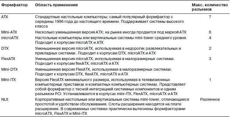
Over the past few years, there has been a shift from the original Baby-AT form factor motherboards used in the first IBM PC and XT computers to the BTX and ATX form factor motherboards used in most full-size desktop and tower systems. There are several variants of the ATX form factor, including microATX (a smaller version of the ATX form factor used in small systems) and FlexATX (an even smaller version designed for lower-end home computers). The BTX form factor involves changing the position of the main components in order to improve system cooling, as well as the use of a thermal module. There are also smaller versions of this form factor - microBTX and picoBTX. There are also other compact form factors such as DTX and mini-ITX, which is a smaller version of FlexATX. The NLX form factor was designed for corporate desktop systems, but over time it was replaced by the FlexATX form factor. The WTX form factor was developed for workstations and servers with medium loads, but was not widely used. Modern form factors and their areas of application are presented in the table below.

Despite the widespread use of Baby-AT, full-size AT and LPX boards, they have been replaced by motherboards of more modern form factors. Modern form factors are actually an industry standard, guaranteeing compatibility of each type of board. This means that an ATX motherboard can be replaced by another board of the same type, another BTX motherboard can be used instead of a BTX motherboard, etc. Thanks to the additional functionality of modern motherboards, the computer industry has been able to quickly move to new form factors. Therefore, it is strongly recommended to purchase systems based on one of the modern form factors.
Motherboards whose parameters do not fit into any of the industry standard form factors should be treated as non-interchangeable. Buy computers with non-standard motherboards only in special circumstances. Repair and modernization of such systems are quite expensive, which is primarily due to the impossibility of replacing motherboards, cases or power supplies with other models. Independent form factor systems are sometimes called “disposable” PCs, which becomes obvious when it comes time to upgrade or repair them after the warranty period expires.
Attention!Nowadays, 'disposable' PCs are more common than ever before. According to some estimates, they account for over 60% of computers sold. This has less to do with the boards used (FlexATX and microATX motherboards are more commonly used today than the LPX models that preceded them), but with the tiny SFX power supplies and narrow micro-tower cases that occupy a privileged position in the modern PC market. Low-cost systems that use a small chassis and a small power supply are, in principle, more suitable for upgrading than previous models. But if you need another expansion connector or, for example, an additional disk drive, then after a while you will literally “run into a wall.” Mini-tower systems are quite cramped and limited, so soon, I believe, they will become “disposable”, like the LPX systems they replaced.
Be especially careful with newer industry standard systems, such as Dell computer models manufactured from 1996 to the present. These computers use a modified power supply and modified ATX board power connectors, which makes these components completely incompatible with standard motherboards and power supplies. Therefore, in order to upgrade the power supply, you will have to use a special Dell-compatible unit. Moreover, when replacing the motherboard with a standard one, you will need to purchase an appropriate power supply and maybe even a case.
So, if you want a truly expandable system, go for a computer with an ATX or BTX motherboard and a mid-tower (or larger) case with at least five drive bays.
Any case that can accommodate a full-size AT motherboard can also accommodate a Baby-AT motherboard. A huge number of Baby-AT form factor motherboards for PCs were produced, equipped with processors of almost all types - from the first 8088 to Pentium III or Athlon; However, installing modern processors seemed to be a very difficult task. As you can see, Baby-AT motherboards have been produced for quite a long time. Although the Baby-AT standard (Fig. 1) is now obsolete, the ATX standard has fully inherited its interchangeability philosophy. In Fig. Figure 2 shows an example of a fairly modern Baby-AT motherboard containing USB, SIMM and DIMM connectors, as well as a connector for connecting an ATX power supply.
The easiest way to identify a Baby-AT class system is to look at the rear panel of the case. Expansion cards are inserted directly into the connectors on the system board and are oriented at an angle of 90° relative to it; in other words, expansion cards are positioned perpendicular to the system board. At the same time, only one connector is noticeable on the rear panel of the Baby-AT motherboard - a 5-pin DIN intended for connecting a keyboard; However, it should be noted that some Baby-AT class systems were equipped with smaller 6-pin mini-DIN connectors (these connectors are often called PS/2) and even a mouse connector. All other connectors were placed either directly on the motherboard or on remote connectors that were connected to the motherboard using cables. The connector for connecting the keyboard is visible through the hole in the case.
Picture 1

Figure 2

All Baby-AT motherboards meet a number of specifications regarding height, mounting hole placement, and connectors (including the keyboard connector), but may vary in width. Motherboards smaller than the standard 9x13 inches (22.86x33.02 cm) were often classified as mini-AT, micro-AT, and sometimes 2/3-Baby or 1/2-Baby form factors. At the same time, they could be normally installed in Baby-AT standard cases.
LPX and Mini-LPX boards were developed by Western Digital in 1987 for their computers. In the name “LPX” the abbreviation LP stands for “Low Profile”. Since the connectors were positioned in such a way that all expansion cards were parallel to the motherboard, it became possible to produce low-profile cases that were smaller in size than Baby-AT class systems.
Although PC motherboards are no longer manufactured by Western Digital, their designs are used by several other manufacturers. Unfortunately, the full specifications were never published; This is especially true for the position of the connectors for installing remote cards. As a result, motherboards from different manufacturers turned out to be non-interchangeable. Some vendors, such as IBM and HP, offered LPX systems that used T-shaped riser cards, allowing expansion cards to be positioned perpendicular to the system board, but still at a certain distance from it. The lack of standardization means that if you have an LPX board installed in your system, in the vast majority of cases you will not be able to replace it with an LPX motherboard from another manufacturer. As a result, you have to deal with a system whose further modernization and repair is practically impossible. Therefore, I do not recommend purchasing LPX systems.
At that time, few people were interested in such a “closed” architecture of systems of this standard, and these boards were very popular from the late 1980s to the mid-1990s. These were primarily systems from Compaq and Packard Bell, as well as a few other companies that used LPX motherboards in their entry-level systems. LPX motherboards were most often used in low-profile cases, although they were also found in tower cases. As noted, these were most often inexpensive systems sold in electronics supermarkets. Today the LPX form factor is considered obsolete.
LPX boards (see picture below) are significantly different from the rest. For example, their expansion connectors are mounted on a separate remote board, which is inserted into the system board. Expansion cards are inserted into a remote card, and their planes are parallel to the system board, which makes it possible to reduce the height of the computer case. Expansion connectors, depending on the design, can be located on one or both sides of the remote board. Manufacturers who used tower cases sometimes used T-shaped remote plates, which made it possible to place expansion connectors perpendicular to the motherboard, but in a slightly elevated position above it.

Another difference between LPX boards is the characteristic placement of connectors on the rear panel - in one row. This includes VGA monitor connectors (15 pins), a parallel port (25 pins), two serial ports (9 pins each), and mini-DIN connectors for a PS/2 keyboard and mouse. All these connectors are mounted on the board itself and, after installation, are located opposite the corresponding holes in the case. Some LPX motherboards have additional built-in connectors, such as a network or SCSI adapter. Because LPX systems featured highly integrated motherboards, many motherboard, chassis, and LPX system manufacturers often referred to their solutions as “all-in-one.”
The dimensions of the LPX and Mini-LPX boards are shown in the figure below.

I am often asked how to recognize the presence of an LPX board in a system. You don't even need to disassemble the case to do this. LPX motherboards differ in that the bus slots in them are placed on a separate board connected to the system board, as in the case of boards of the NLX form factor. Therefore, all its connectors are parallel to the motherboard. This can be easily determined by looking at the back of the case. If all connectors are parallel to the system board, then a remote card is used. This is a sure sign of LPX. In addition, in LPX all connectors are located at the bottom and lined up in one line. All LPX motherboards, regardless of shape, size, or bypass placement, require all external ports to be located at the rear edge of the board (see figure below). At the same time, according to the Baby-AT standard, connectors are used for serial and parallel ports, PS/2 port, as well as USB ports. In this case, on ATX and BTX motherboards, all external ports are grouped to the left of the expansion connectors.

As already noted, the remote board is also used in NLX boards. But in LPX it is placed in the middle of the motherboard, and in NLX it is on the side, and it is actually connected to the motherboard.
The figure below shows two typical examples of connectors on LPX motherboards. Please note that not all LPX boards have built-in audio, so the corresponding connectors may not be available. Additionally, USB (or other ports) may be missing, although the general port layout remains the same. The connectors along the rear edge of the boards may “conflict” with the bus connectors. This is why remote boards are used. The presence of built-in connectors is an undoubted advantage of LPX, and, unfortunately, Baby-AT boards lack it. However, LPX boards are not standardized and are not fully interchangeable, so choosing a board with the LPX form factor cannot be called successful. New motherboard form factors such as ATX, microATX and NLX have built-in connectors and also follow some standard. The LPX's breakout card design allowed system designers to create small-sized computers, a trend that the new NLX form factor continued. This form factor, in fact, was created as a modern replacement for LPX.
Good day, dear readers of our tech blog. Today we will look at the main form factors of motherboards as of 2018. We would like to immediately clarify that the classification will only include devices for home use. Modern server MPs CEB and EEB are not discussed here, although we will also talk about them later.
From this article you will learn:
What will the review consist of? Here you will receive comprehensive information about the maximum dimensions of the board, the number of ports used, the layout of connectors and more. We hope our article will help you determine the optimal motherboard for your computer if you have not already done so.
Is there a lot of choice?
 Today, there are several popular types, or rather form factors, of motherboards on the market. Among the key ones we note:
- E-ATX;
- MicroATX;
- Mini-ITX;
- Mini-STX.
How to find out and determine the optimal format? So let’s figure it out together, and at the same time discuss which form factor is better.
ATX
ATX (Advanced Technology Extended)– the most common MP standard at the moment. It was developed by Intel back in 1995 as an alternative to the AT form factor, popular at that time, but gained real fame only in 2001. Among the basic differences from its predecessor, it is worth noting the following:
- CPU power management by the motherboard. The process occurs even when turned off: a voltage of 5 or 3.3 volts is systematically applied to the CPU and some peripheral connectors;
- The power supply circuit has been significantly changed to the more common today version of 24+4 or 24+8 pin;
- The rear panel has a fixed rectangular size, and all components and peripheral devices are now connected without the use of adapters and additional cables. Each MP manufacturer can arbitrarily change the location of the outputs by providing a plug for the rear of the system unit;
- The mouse and keyboard have a standard PS/2 connection connector (nowadays mostly USB).
All power connectors on the motherboard are located at the edges of the PCB, providing both aesthetic beauty and ease of connecting peripheral devices and the power supply. The central part contains the socket, slots for RAM, PCI-Ex, and the south bridge.  Standard size – 305x244 mm. There are 8 to 9 mounting holes for mounting to the body.
E-ATX
E-ATX (Extented)– a derivative case from ATX, which differs primarily in the size of the board – 305x330 mm. Often, on the basis of this motherboard, top gaming solutions are assembled for the current sockets 1151, 2066 (Intel), AM4 and TR4 (AMD).
The key difference from standard ATX is more expansion slots (up to 8 ports for RAM), a more sophisticated power supply system for components, improved cooling and, which happens quite often, a standard cooling system.
I would especially like to mention server dual-processor E-ATX motherboards. Additional 86 mm allows you to easily place on one sheet of textolite up to 16 ports for RAM and expansion slots (video cards, network cards, RAID controllers).
Among the shortcomings, it is worth noting only the selection of the appropriate case, since the vast majority of Midi-Tower solutions for ATX boards are simply not suitable.
MicroATX
MicroATX (mATX, uATX, µATX)- another derivative of ATX, which was created by the same Intel in 1997. Boards of this form factor are practically no different from standard analogues, with one exception - the dimensions are 244x244 mm, which cuts off the entire bottom panel with expansion ports and moves the SATA ports to the side panel, optimizing the available PCB space.
The mounting holes are made in such a way that MicroATX can be installed in standard ATX cases without any problems. , socket and other architectural aspects are not affected.  The standard was originally conceived as an office standard, and therefore the set of peripherals and connection ports in MicroATX is more modest than that of its full-format analogue. However, modern models can easily create a base for the following PCs on the board:
- server;
- multimedia;
- gaming;
- workstations;
- HTPC;
- rendering machines.
The only drawback is essentially the inability to connect a second video card due to the lack of a second full PCI-E x16.
Mini-ITX
Mini-ITX– an even more compact version of ATX, only its dimensions do not exceed 170x170 mm. Mechanical compatibility with all components and support for modern chips is maintained. The form factor was created in 2001 by VIA Technologies with the sole purpose of promoting its own processor, but something went wrong, and the stone never gained popularity, which cannot be said about MP.
A distinctive feature of Mini-ITX is the built-in processor in some board models that are soldered at the factory by the manufacturer. It cannot be replaced by words at all. On the one hand, the solution is not the most practical, but on the other hand, this procedure significantly reduces the cost of production (no need to think about inserting a socket) and the final cost of the product. The architecture allows you to create the coolest possible (TDP of built-in CPUs does not exceed 15 W), silent and fast office stations (SSD + 16 GB of DDR4 2400 MHz RAM).  Ideal solution for HTPC or multimedia center. Although a gaming system can also be built on such a board. Just take a closer look at the MSI B350I Pro AC. The board has standard power supply and supports overclocking of components. Add a Ryzen 5 2400G and you've got the perfect system for the soul.
Mini-STX
Mini-STX (Mini Socket Technology Extended)– a relatively recent standard, developed by the same Intel. It has dimensions of 147x140 mm, which is comparable to a DVD sleeve.
It differs from Mini-ITX in the complete lack of support for PCI-E x16 connectors, as well as in a modified port for connecting a power supply. Here the output has a pin type, as on most modern laptops. This step is partly dictated by the fact that the board and components on it are low-power. On the other hand, it is somehow inhumane to solder 24+4 pins in such an area.
To create a full-fledged PC, it provides the ability to connect SATA or M.2 drives, RAM and a processor with a built-in video core. Miniature dimensions will allow you to place the board in a miniature case with the dimensions of a PS4 or XBOX One.
The main disadvantage is the need for a power supply for Mini-STX boards.
conclusions
So, comparison of different architectures comes down mainly to overall dimensions and quantity on the board. On the good side, the need for ATX models is becoming less and less every year, since MicroATX offers similar functionality and does not require a case larger than a mid-tower. Lack of additional PCI-E x16/x8/x4 slots?
The modern industry is moving away from further support for SLI and Crossfire, making it impractical to power additional slots unless you're mining or want to connect a super-fast NVMe SSD, capture card, or ASUS Xonar-class audio card.
We hope we helped you with choosing a motherboard for your future system. What it will be is another matter, but the main idea has been received, now we need to implement it. Good luck! Don't forget to share with your loved ones, bye.
Case form factor is the aspect ratio, for example 3:2 for a rectangle. In a technical sense, this is first of all setting the geometry of the device. In full meaning - this is geometry plus power parameters (voltage, distribution across contacts, etc.), plus additional options .
It is in this meaning that the term form factor is used for cases and motherboards. The parameter is directly related to the compatibility of the case with motherboards. There are specifications for cases and motherboards (since these devices must be compatible with each other), which define the form factors of these devices. The main difference is different power supplies, incompatible with each other.
Form factor AX - obsolete form factor. Specification issued by IBM, obsolete. Used for old, used or inexpensive computers. Has 4 families of sizes. The most commonly used size is BAT, sometimes this form factor is called that. The name “depth” indicates its primary use on desktops. Family Features:
- Full AT - used exclusively in servers, because reached 12" wide.
- Baby AT - normal size.
- Depth 3/4 And 2/3 from the depth of BAT at the same width.
Only 5V is supplied to the AT boards, and 3.3V is obtained by the voltage converter on the board itself; From the power supply there are two connectors to the board (the black wires should go to the middle!). On the AT-e, all connectors are collected in one place, as a result of which either cables from the communication ports stretch across the entire motherboard to the rear of the case, or from the IDE and FDD ports to the front; slots for memory modules almost under the power supply. The cooling issue was not resolved successfully - the air does not flow directly to the processor.
Form factor ATX - specification released by Intel in the mid-90s. ATX is revealed as AT Extension, which means an evolution of AT. New versions of the ATX specification are released periodically, for example. version 2.03 from 1998. Family Features:
- ATX - large size (305x244 mm), allowing you to place as many as 7 expansion card slots (PCI, AGP, AMR, CNR, ACR, ISA). The board is compatible with desktop and tower cases. It is analogous to Baby AT.
- Mini-ATX - has smaller dimensions (284x208 mm) and allows you to place 6 card slots. Compatible with the same cases as ATX.
- MicroATX - reduced ATX (244x244 mm): the large side of the rectangle has been reduced to a square. Allows you to place 4 slots. The main application is office computers.
- FlexATX - an even smaller version of MicroATX (229x191 mm). One of its uses is Internet set-top boxes. MicroATX and FlexATX are sometimes called SFX.
The AT boards are supplied with a ready voltage of 3.3V; There is one connector per board from the power supply; board layout that reduces the length of interface cables; shutting down the computer from the OS.
The color of the ATX standard wires is as follows:
|
Chain |
Wire color |
Explanation |
|
Red |
Main voltage |
|
|
Yellow |
Power supply for device motors and interface circuits |
|
|
White |
Not used. Present to comply with ISA Bus standard |
|
|
Blue |
Power supply for interface circuits |
|
|
3.3V |
Orange |
CPU power |
|
3.3V Sense |
Brown |
Stabilizer feedback signal +3.3V |
|
5VSB |
Crimson |
Standby low-power source +5V |
|
PS-ON |
Green |
Signal to turn on power supplies |
|
PW-OK |
Grey |
Power signal is normal |
|
Black |
General, relative to supply voltages |
Form factor LPX, NLX - The LPX specification was intended for use in enclosures Slimline or Low-profile. Was introduced rack. Those. expansion cards are not inserted into the motherboard, but into a vertical rack connected to the board, parallel to the motherboard. This made it possible to significantly reduce the height of the case, the maximum number of connected cards is 2-3 pieces. Another innovation born in LPX is a video chip integrated on the motherboard. The case size for LPX is 9x13", for Mini-LPX - 8 x 10". After the emergence of NLX, LPX began to be replaced.
The ultra-compact standard was born again in November 1997 when Intel introduced the NLX specification. Today NLX is an open motherboard specification low profile (v.1.2), i.e. The form factor was developed jointly by many PC suppliers. In NLX, the expansion slots are located on a separate card, which makes it easy to remove the motherboard - all expansion cards remain in this separate card.
In addition, the form factor was developed as a solution for building low-cost NetPC systems. The specification also requires a special case, since the NLX design allows expansion cards and the motherboard to be located on special rails for easy removal from the case. The case form factor is sometimes called NLX-slim. A special card for expansion cards is installed on the system board ( riser card). Designed for use in various types of systems.
Family sizes: NLX (large size) - 400x400x100 mm, microNLX(small size) - 210x254 mm. Main differences of NLX:
- supports current and future processors;
- supports graphics capabilities via AGP graphics port;
- supports high-block memory technology;
- provides flexibility in system development and integration (for example, it makes it possible to replace boards even without unscrewing the screws).
ITX form factor - n new specification. The Mini-ITX standard was developed by VIA Technologies and introduced by it in November 2001 (the so-called Total Connectivity initiative, including the development of “systems-in-the-motherboard”). Systems in a Mini-ITX case do not require ventilation. The compactness of Mini-ITX allows the production of silent, full-featured systems that take up very little space. Family sizes:
- ITX - large size (215x191 mm).
- Mini-ITX - small size (170x170 mm).
WTX form factor- powerful workstations and servers are also not satisfied with AT and ATX specifications. There, the foreground comes to ensure normal cooling, placement of large amounts of memory, convenient support for multiprocessor configurations, greater power supply power, placement of a larger number of data storage controller ports and input/output ports, i.e. cost does not play the most important role.
Thus, in 1998, the specification was born WTX, focused on supporting dual-processor motherboards of any configuration, supporting today's and tomorrow's video card and memory technologies.
In this specification, the developers tried to move away from the usual model, when the motherboard is attached to the case through mounting holes located in certain places. Here it is attached to BAP (Board Adapter Plate), and the mounting method is left up to the board manufacturer, and the standard BAP attached to the body.
WTX describes the architecture Flex Slot . Such cards can accommodate any PCI, SCSI or IEEE 1394 controllers, sound, network interface, parallel and serial ports, USB, and means for monitoring the system state.The first production samples of WTX appeared in the fall of 1999.
Solutions based on 2.5" and 3.5" form factor hard drives
|
Often, instead of specifying a specific hard drive form factor in inches(and the double quote denotes exactly inch), computer hardware suppliers use the acronyms SFF and LFF, abbreviations for the phrases Small Form Factor and Large Form Factor, respectively. It is not difficult to guess that any (both SATA and SAS) hard drives of a smaller form factor 2.5" received the designation SFF HDD, but more 3.5" - LFF HDD. It is no secret that in modern high-performance hard drives of 3.5" and 2.5" form factors, manufacturers use platters of the same size - from 2.5" HDD. Therefore, often, both the capacity and performance parameters of 2.5" and 3.5" hard drive models from the same manufacturer look the same Moreover, some manufacturers have announced the cessation of production of high-performance 3.5" hard drives, leaving top HDD models only in the 2.5" form factor. The availability of high-performance 3.5" form factor hard drives is steadily declining. Based on the realities of the modern market, manufacturers consider it economically infeasible to use more than 2 platters inside one hard drive. For reference, it is possible to install up to 3 platters in a 2.5" form factor hard drive (15mm high), and up to 5 platters in a 3.5" HDD. |
 2.5" drive |
 3.5" drive |
 |
What should those consumers do who cannot or do not want (for various reasons) to use modern 2.5" form factor hard drives? Manufacturers offer an intermediate solution - the use of 2.5" hard drives in a 3.5" form factor. As a 3.5" hard drive, a regular 2.5" hard drive is offered, installed at the factory by the manufacturer in a special metal mounting case - a carriage. Please note that removing this hard drive from the mounting enclosure may not be covered under warranty for some manufacturers. Among the undoubted advantages of this design, it should be noted that the engineers of the manufacturing companies accurately calculate the dimensions and rigidity of the structure, guarantee the standard arrangement of connectors and mounting holes for 3.5" hard drives, and ensure optimal cooling of the hard drive installed inside. |
If the transition to a smaller form factor is inevitable, what will consumers benefit from switching to a 2.5" hard drive form factor?
What are the differences, pros and cons of disk subsystems based on hard drives of various form factors and their scope of application? In two words - what's the difference?
Obviously, the smaller the hard drive, the more such hard drives should fit inside the server.
Today, the following number of hard drives are traditionally installed in rack-mounted servers:
| server height | number of 3.5" bays | number of 2.5" bays | ||||
| 1U | 4 compartments | 8 compartments | ||||
| 2U | 12 compartments | 24 compartments | ||||
| 3U | 16 compartments | 32 compartments | ||||
| 4U | 24 compartments | 48 compartments | ||||
In the general case (as can be seen from the table), it is possible to install 2 times more 2.5" form factor hard drives in servers compared to servers of the same size but with 3.5" hard drives.
As mentioned earlier, in the segment of enterprise-class hard drives, the maximum capacity of drives of two different form factors is the same, based on this, the use of a disk subsystem with 2.5" bays allows you to double the maximum total storage capacity. And even when using low-price hard drives range, in which, today, the maximum capacity of 3.5" form factor hard drives is approximately 2 times greater than that of 2.5" drives, the maximum capacity of disk subsystems with bays of different form factors will be approximately the same.
As an additional bonus of using 2.5" hard drives, it is obvious that due to the smaller dimensions (a 2.5" drive is smaller than a 3.5" drive in depth), the disk subsystem in the server occupies less space, which allows manufacturers to slightly reduce the size of servers. It should also be noted that most Modern SSDs (solid-state drives) are available in a 2.5" form factor and the use of 2.5" bays in the server guarantees compatibility when installing SSD drives, and, what is especially important, in the future - with possible server upgrades.
|
Smaller hard drives are actively used in systems with small dimensions, in high-density servers, modular and blade servers. For example, in one 2U high case there are 4 dual-processor servers and 24 2.5" form factor hard drives, that is, 6 2.5" form factor hard drives are connected to each server at once. To obtain the same number of 3.5" disks, the server case must be 2 times higher - not 2U, but 4U high. Such a parameter as the maximum amount of disk space is of course important, but not always. In enterprise-class server disk subsystems, disk subsystem performance (input/output operations per second, IOPS) is much more important than the total disk storage capacity. The number of RAID groups (LUNs) of the disk subsystem and their performance (IOPS) increase with the number of connected hard drives, so it is obvious that a larger number of 2.5" disks will provide a serious advantage compared to a small array of 3.5" HDDs. |
For comparison, two 2.5" enterprise-class 10,000rpm (revolutions per minute) hard drives on a good RAID controller will outperform one 3.5" drive with 15,000rpm. At the same time, the price of two 2.5" 10,000rpm disks with a capacity of 300GB and one 3.5" 15,000rpm disk with a capacity of 600GB will be approximately the same.
Such a parameter as the linear read/write speed on external tracks, theoretically, should be higher for 3.5" hard drives than for 2.5" (at the same spindle speed and the same recording density) simply due to the physically larger size of the platters, but in reality there are differences are insignificant, since high-performance hard drives of different form factors often contain platters of the same size.
In general, the more hard drives a server has, the greater the power consumption (the power supplies must be more powerful) and the greater the heat dissipation (the server ventilation system and cooling costs must be more powerful). However, compared to 3.5" hard drive models, modern 2.5" hard drives have 2 times lower power consumption (in all modes) and, as a result, lower heat generation and cooling costs. Thus, a server with 24 2.5" hard drives consumes less electricity and heats the surrounding space than a server with 12 3.5" hard drives.
Great attention is always paid to the reliability of hard drives. Due to the reduction in size (and additional engineering solutions), 2.5" hard drives have increased resistance to vibration and mechanical stress. This is confirmed by the manufacturers themselves; the mean time between failures (MTBF) of the latest models of 2.5" hard drives is 2 million hours, compared to the best models of 3.5" hard drives, whose MTBF is declared at 1.3-1.6 million hours.
And lastly, despite the fact that this is not relevant in servers, 2.5" drives produce slightly less noise during operation compared to 3.5" models.
As a result, we can briefly formulate the pros and cons, as well as the areas of application of hard drives of various form factors.
Advantages of hard drives in different form factors.
- 3.5" LFF - more capacity per disk, less price per gigabyte:
- with the same recording density, more information can be placed on a larger platter
- the maximum capacity of one HDD is greater (in the segment of low-price hard drives)
- cheaper cost per gigabyte of disk space
- 2.5" SFF - more capacity and performance per unit of space occupied by a server or rack storage system:
- 2 times more storage capacity in a limited space - smaller dimensions and, as a result, higher capacity density per unit volume of space (Gigabyte/cm3) or per unit of server size in a rack (Gigabyte/Unit)
- higher performance of the storage system in limited space - smaller dimensions and, as a result, higher I/O density of the disk subsystem per unit volume of space (IOPS/cm3) or per unit size of the server in the rack (IOPS/Unit)
- 2 times less energy consumption (in all modes) and, as a result, less heat generation and cooling costs , modular and blade servers
- in systems with high disk subsystem performance due to a large number of fast hard drives -
- in systems with a large number of RAID groups -
- in systems with maximum reliability of all components -
- in systems with low or limited power consumption -
Today there are four predominant motherboard sizes - AT, ATX, LPX and NLX. In addition, there are smaller versions of the AT (Baby-AT), ATX (Mini-ATX, microATX) and NLX (microNLX) formats. Moreover, an extension to the microATX specification was recently released, adding a new form factor to this list - FlexATX. All these specifications, which determine the shape and size of motherboards, as well as the arrangement of components on them and the features of the cases, are described below.
AT
The AT form factor is divided into two modifications that differ in size - AT and Baby AT. The size of a full-size AT board reaches up to 12" wide, which means that such a board is unlikely to fit into most of today's cases. Installation of such a board will likely be hampered by the drive and hard drive bay and power supply. In addition, the location of the board components on a large distance from each other can cause some problems when working at high clock speeds.Therefore, after motherboards for the 386 processor, this size is no longer found.
Thus, the only motherboards made in the AT form factor that are widely available are boards corresponding to the Baby AT format. The Baby AT board measures 8.5" wide x 13" long. In principle, some manufacturers may reduce the length of the board to save material or for some other reason. To secure the board in the case, three rows of holes are made in the board.
All AT boards have common features. Almost all have serial and parallel ports, connected to the motherboard via connecting strips. They also have one keyboard connector soldered onto the board at the back. The processor socket is installed on the front side of the board. SIMM and DIMM slots are found in various locations, although they are almost always located on the top of the motherboard.
Today this format is gradually disappearing from the scene. Some companies still produce some of their models in two versions - Baby AT and ATX, but this is happening less and less. Moreover, more and more new features provided by operating systems are implemented only on ATX motherboards. Not to mention just ease of use - for example, most often on Baby AT boards all the connectors are collected in one place, as a result of which either cables from communication ports stretch almost across the entire motherboard to the rear of the case, or from IDE and FDD ports to front Sockets for memory modules that fit almost under the power supply. With limited freedom of action inside the very small space of the MiniTower, this is, to put it mildly, inconvenient. In addition, the issue with cooling was poorly resolved - the air does not flow directly to the part of the system that needs cooling most - the processor.
LPX
Even before the advent of ATX, the first result of attempts to reduce the cost of PCs was the LPX form factor. Intended for use in Slimline or Low-profile cases. The problem was solved by a rather innovative proposal - the introduction of a stand. Instead of inserting expansion cards directly into the motherboard, this option places them in a vertical rack that connects to the board, parallel to the motherboard. This made it possible to significantly reduce the height of the case, since usually it is the height of expansion cards that affects this parameter. The price for compactness was the maximum number of connected cards - 2-3 pieces. Another innovation that has begun to be widely used on LPX boards is the video chip integrated on the motherboard. The case size for LPX is 9 x 13"", for Mini LPX - 8 x 10"".
After the introduction of NLX, LPX began to be replaced by this form factor.
ATX
It is not surprising that the ATX form factor in all its modifications is becoming increasingly popular. This is especially true for boards for processors on the P6 bus. So, for example, of the LuckyStar motherboards for these processors being prepared for release this year, 4 will be in Mini-ATX format, 3 - ATX, and only one - Baby AT. And if you also take into account that today there are much fewer motherboards for Socket7 being made, if only because of the much smaller number of new chipsets for this platform, then ATX wins a convincing victory.
And no one can say that it is unfounded. The ATX specification, proposed by Intel back in 1995, is aimed precisely at correcting all those shortcomings that have emerged over time in the AT form factor. And the solution, in fact, was very simple - rotate the Baby AT board 90 degrees and make appropriate adjustments to the design. By that time, Intel already had experience in this area - the LPX form factor. ATX embodied the best aspects of both Baby AT and LPX: expandability was taken from Baby AT, and high integration of components was taken from LPX. Here's what happened as a result:
- Integrated I/O port connectors. On all modern boards, I/O port connectors are present on the board, so it seems quite natural to place their connectors on it, which leads to a fairly significant reduction in the number of connecting wires inside the case. In addition, at the same time, among the traditional parallel and serial ports, keyboard connector, there was also a place for newcomers - PS/2 and USB ports. In addition, as a result, the cost of the motherboard has decreased slightly due to the reduction in cables included.
- Significantly increased ease of access to memory modules. As a result of all the changes, the sockets for memory modules have moved further from the slots for motherboards, from the processor and the power supply. As a result, expanding memory has become a matter of minutes in any case, whereas on Baby AT motherboards you sometimes have to take a screwdriver.
- Reduced distance between the board and disks. The connectors of the IDE and FDD controllers have moved almost close to the devices connected to them. This allows you to reduce the length of cables used, thereby increasing the reliability of the system.
- Separation of the processor and slots for expansion cards. The processor socket has been moved from the front of the board to the back, next to the power supply. This allows you to install full-size boards in the expansion slots - the processor does not interfere with them. In addition, the cooling problem has been resolved - now the air sucked in by the power supply blows directly onto the processor.
- Improved interaction with the power supply. Now one 20-pin connector is used, instead of two, as on AT boards. In addition, the ability to control the motherboard power supply has been added - turning it on at the right time or upon the occurrence of a certain event, the ability to turn it on from the keyboard, turn it off by the operating system, etc.
- Voltage 3.3 V. Now the 3.3 V supply voltage, which is very widely used by modern system components (take PCI cards for example!) comes from the power supply. In AT boards, a stabilizer installed on the motherboard was used to obtain it. There is no need for it in ATX boards.
The specific size of motherboards is described in the specification largely based on the convenience of developers - from a standard plate (24 x 18'') you can get either two ATX boards (12 x 9.6'') or four - Mini-ATX (11.2 x 8.2'') . By the way, compatibility with older cases was also taken into account - the maximum width of an ATX board, 12’’, is almost identical to the length of AT boards, so that it would be possible to use an ATX board in an AT case without much effort. However, today this is more in the realm of pure theory - the AT case still needs to be found. Also, whenever possible, the mounting holes on the ATX board are fully compatible with AT and Baby AT formats.
microATX
The ATX form factor was developed back in the heyday of Socket 7 systems, and much of it today is somewhat out of date. For example, a typical combination of slots, based on which the specification was compiled, looked like 3 ISA/3 PCI/1 adjacent. Somewhat irrelevant today, isn't it? ISA, no AGP, AMR, etc. Again, 7 slots are not used 99 percent of the time anyway, especially today with chipsets like the MVP4, SiS 620, i810, and other similar products coming out. In general, for cheap PCs, ATX is a waste of resources. Based on similar considerations, in December 1997, the microATX format specification was presented, a modification of the ATX board designed for 4 slots for expansion cards.
In fact, the changes compared to ATX were minimal. The size of the board was reduced to 9.6 x 9.6’’, so that it became completely square, and the size of the power supply was reduced. The I/O connector block remains unchanged, so the microATX board can be used in an ATX 2.01 case with minimal modifications.
NLX
Over time, the LPX specification, like the Baby AT, no longer met the requirements of the time. New processors were released, new technologies appeared. And it was no longer able to provide acceptable spatial and thermal conditions for the new low-profile systems. As a result, just as ATX replaced the Baby AT, the NLX form factor specification appeared in 1997, as the LPX idea evolved, taking into account the emergence of new technologies. A format aimed at use in low-profile cases. When creating it, both technical factors were taken into account (for example, the advent of AGP and DIMMs, integration of audio/video components on the motherboard) and the need to provide greater ease of service. Thus, to assemble/disassemble many systems based on this form factor, a screwdriver is not required at all.

As can be seen in the diagram, the main features of the NLX motherboard are:
- Rack for expansion cards, located on the right edge of the board. Moreover, the motherboard can be freely detached from the rack and pulled out of the case, for example, to replace the processor or memory.
- The processor is located in the left front corner of the board, directly opposite the fan.
- In general, grouping tall components, such as the processor and memory, at the left end of the board to allow rack placement of full-size expansion cards.
- Located at the rear end of the board are single-height (in the area of expansion boards) and double-height I/O connector blocks to accommodate the maximum number of connectors.
In general, the stand is a very interesting thing. In fact, this is one motherboard, divided into two parts - the part where the system components themselves are located, and the part connected to it via a 340-pin connector at an angle of 90 degrees, where all kinds of input/output components are located - expansion cards, port connectors, drives data where the power is connected. Thus, firstly, ease of maintenance is increased - there is no need to access components that are currently unnecessary. Secondly, as a result, manufacturers have greater flexibility - they make one model of the main board and a rack for each specific customer, with the necessary components integrated on it.
In general, does this description remind you of anything? A rack mounted to the motherboard that carries some I/O components instead of being integrated onto the motherboard, all to make it easier to service, give manufacturers more flexibility, etc.? That's right, some time after the release of the NLX specification, the AMR specification appeared, describing a similar ideology for ATX boards.
Unlike the rather strict other specifications, NLX provides manufacturers with much greater freedom in decision making. NLX motherboard sizes range from 8 x 10'' to 9 x 13.6''. The NLX case must be able to handle both these two formats, and all intermediate ones. Typically, boards that fit within the minimum dimensions are designated as Mini NLX. It is also worth mentioning an interesting detail: the NLX case has USB ports located on the front panel - very convenient for identification solutions like e.Token.
It only remains to add that according to the specification, some places on the board must remain free, providing opportunities for expanding functions that will appear in future versions of the specification. For example, to create motherboards for servers and workstations based on the NLX form factor.
WTX

However, on the other hand, powerful workstations and servers with AT and ATX specifications are also not entirely satisfied. There are problems there, where cost does not play the most important role. At the forefront are ensuring normal cooling, placement of large amounts of memory, convenient support for multiprocessor configurations, greater power supply power, placement of a larger number of data storage controller ports and I/O ports. Thus, in 1998, the WTX specification was born. Focused on supporting dual-processor motherboards of any configuration, supporting today's and tomorrow's video card and memory technologies.
Particular attention, perhaps, should be paid to two new components - Board Adapter Plate (BAP) and Flex Slot.
In this specification, the developers tried to move away from the usual model, when the motherboard is attached to the case through mounting holes located in certain places. Here it is attached to the BAP, and the method of attachment is left to the board manufacturer, while the standard BAP is attached to the case.
Besides the usual things like board dimensions (14 x 16.75""), power supply specs (up to 850 W), etc., the WTX specification describes the Flex Slot architecture - in a sense, AMR for workstations. Flex Slot is designed to improve serviceability, provide additional flexibility to developers, and reduce motherboard time to market. A Flex Slot card looks something like this:

Such cards can accommodate any PCI, SCSI or IEEE 1394 controllers, sound, network interface, parallel and serial ports, USB, and means for monitoring the system state.
Samples of WTX boards should appear around June, with production samples expected in the third quarter of 1999.
FlexATX
And finally, just as ATX emerged from the ideas contained in the Baby AT and LPX, the development of the microATX and NPX specifications led to the emergence of the FlexATX form factor. This is not even a separate specification, but just an addition to the microATX specification. Looking at the success of the iMac, which, in fact, had nothing new except its appearance, PC manufacturers also decided to follow this path. And the first was Intel, which in February at the Intel Developer Forum announced FlexATX - a motherboard 25-30 percent smaller in area than microATX.
Theoretically, with some modifications, the FlexATX board can be used in cases that meet the ATX 2.03 or microATX 1.0 specifications. But for today’s cases there are enough boards without this; we were talking about elaborate plastic designs, where such compactness is needed. There, at IDF, Intel demonstrated several possible options for such cases. The imagination of the designers ran wild - vases, pyramids, trees, spirals, which were not offered. A few phrases from the specification to deepen the impression: “aesthetic value”, “greater satisfaction from owning the system.” Not bad for describing the form factor of a PC motherboard?

Flex - that's why it's flex. The specification is extremely flexible, and leaves many things to the discretion of the manufacturer that were previously strictly described. Thus, the manufacturer will determine the size and placement of the power supply, the design of the I/O card, the transition to new processor technologies, and methods for achieving a low-profile design. In practice, only the dimensions are more or less clearly defined - 9 x 7.5 "". By the way, regarding new processor technologies - Intel at IDF demonstrated a system on a FlexATX board with a Pentium III, which until the fall was announced only as Slot-1, and in the photo - see for yourself, and the specification emphasizes that FlexATX boards are only for Socket processors...
And finally, another interesting revelation from Intel - in three years, in the next specifications, the power supply may even be located outside the PC case.