Installing and configuring Arduino on Windows OS. Connecting arduino
In this article we will look at installing drivers for boards that were developed by Arduino and have standard USB to UART adapters (which have default drivers in the Arduino IDE folder) such as ATmega16U2, FT232RL.
In case you have a Chinese version of the board with a converter to CH340G please use this guide
Installing the driver in the Windows operating environment
As an example, we will look at installing a driver for Arduino UNO.
Considering the fact that the Arduino UNO and Arduino Mega boards use the same microcircuits as USB to UART converter chips (early versions of Atmega 8U2, R3 versions already use 16U2), the installation will proceed in the same way. Similarly, everything will happen for the Arduino nano, even though the nano uses the FT232RL as a converter chip.
Part 1. Automatic driver installation
If your computer is connected to the Internet, then most likely the driver will be installed automatically and you don’t have to read the rest of the article.
Part 2. Manual driver installation
So, after unpacking the environment, we connect the Arduino board to the computer. If the drivers are not installed automatically, you will see the following window:
Don't be alarmed. This is a common occurrence. The driver will have to be installed manually.
Go to My Computer/Properties/Device Manager.

Double-click on “Unknown Device”.
Click "Update Driver".

Select "Search for drivers on this computer."

We indicate the directory where you installed the Arduino IDE, or rather its child folder “drivers”. Leave the "Including nested subfolders" checkbox.

Windows Firewall is ready as always. Click "Install this driver anyway".

We wait for some time. That's it, the drivers are installed and our board is ready for use.

After you have successfully completed these steps, all that remains is to open the IDE, select COM port who decided on the board, select the board itself from the list and plunge headlong into the interesting world of Arduino.
In my article, I would like to talk in detail and with illustrations about the connection diagram and pinout of Arduino, looking at various models of the microcontroller.
1. Arduino Uno board - device pinout
The word Uno is translated from Italian as “one”. The device is named in connection with the beginning of the release of Arduino 1.0. In other words, Uno is the reference model for the entire Arduino-type platform. This is the latest in a series of USB boards that have proven their effectiveness and stand the test of time.

Arduino Uno is created on an ATmega 328 microcontroller (datasheet).
His compound next:
- the number of digital inputs and outputs is 14 (and six of them can be used as PWM outputs);
- the number of analog inputs is six;
- 16 MHz – quartz resonator;
- there is a power connector;
- there is a connector designed for ICSP programming inside the circuit itself;
- There is a reset button.
It is extremely important to note that a distinctive feature of all new arduino boards is the use of an ATmega 16U2 microcontroller (or ATmega 8U2 in versions R1, R2) for the USB-UART interfaces instead of the outdated FTDI type microcircuit.
The Uno board version R2 is equipped with an additional pull-up resistor on the HWB line of the microcontroller used.

Pinout as follows:
- The serial interface uses buses No. 0 (RX – data reception), No. 1 (TX – data transmission).
- For external interruption, pins No. 2, No. 3 are used.
- For PWM, pins numbered 3.5, 6, 9, 10, 11 are used. The analog Write function provides a resolution of 8 bits.
- Communication via SPI: pins No. 10 (SS), No. 11 (MOSI), No. 12 (MISO), No. 13 (SCK).
- Pin No. 13 powers the LED, which lights up at high potential.
- Uno is equipped with 6 analog inputs (A0 – A5), which have a resolution of 10 bits.
- To change the upper voltage limit, use the AREF pin (analog Reference function).
- I2C communication (TWI, Wire library) is carried out through pins No. 4 (SDA), No. 5 (SCL).
The device is built on an ATmega16U2 microcontroller and has an increased level of noise immunity in the reset circuit.

The device differs from the previous version only in that in this case the USB-UART FTDI interface is not used when connecting to a computer. This task is performed by the ATmega 16U2 microcontroller itself.
The board pinout changes look like this:
- Two pins have been added near the AREF pin: SDA, SCL.
- Two pins have also been added near the RESET pin: IOREF, which allows you to connect expansion cards with adjustment to the required voltage; the second pin is not used and is in reserve.
It is one of the simplest and most convenient Arduino devices.

An ATmega 168 microcontroller with an operating voltage of 5 volts and a frequency of 16 MHz is used. The maximum supply voltage in models is 9 volts. The maximum current at the terminals is 40 mA.
The fee contains:
- 14 digital pins (6 of them can be used as PWM outputs), can be used as both input and output;
- 8 analog inputs (4 of them are equipped with pins);
- 16 MHz – crystal oscillator.

Device pins Arduino Mini has the following purposes:
- Two pins through which the plus board is powered: RAW, VCC.
- The minus contact output is the GND pin.
- Pins numbered 3, 5, 6, 9, 10, 11 are used for PWM when using the analog Write function.
- Other devices can be connected to pins No. 0, No. 1.
- Analog inputs No. 0 – No. 3 with outputs.
- Analog inputs No. 4 – No. 7 do not have pins and require soldering if necessary.
- AREF pin, which is designed to change the upper voltage.
The pin layout may vary between different versions of arduino mini.
The Arduino Mega 2560 device is assembled on the ATmega 2560 microcontroller (datasheet), and is an updated version of the Arduino Mega.

To carry out the conversion of USB-UART interfaces, a new microcontroller ATmega 16U2 (or ATmega 8U2 for versions of boards R1 or R2) is used.
Board composition next:
- the number of digital inputs/outputs is 54 (15 of them can be used as PWM outputs);
- number of analog inputs – 16;
- Serial interfaces are implemented using 4 UART hardware transceivers;
- 16 MHz – quartz resonator;
- USB connector;
- power connector;
- in-circuit programming is carried out via the ICSP connector;
- reset button.

The Mega 2560 R2 version adds a special resistor that pulls the 8U2 HWB line to ground, which greatly simplifies the transition of the Arduino to DFU mode, as well as updating the firmware. Version R3 differs slightly from previous ones. The changes in the device are as follows:
- four pins were added - SCL, SDA, IOREF (to ensure voltage compatibility of various expansion boards) and another reserve pin, not yet used;
- increased noise immunity in the reset circuit;
- increased memory capacity;
- ATmega8U2 has been replaced by the ATmega16U2 microcontroller.
The findings are intended to be as follows:
- The available digital pins can serve as input/output. The voltage on them is 5 volts. Each pin has a pull-up resistor.
- Analog inputs do not have pull-up resistors. The operation is based on the use of the analog Read function.
- The number of PWM pins is 15. These are digital pins No. 2 - No. 13, No. 44 - No. 46. PWM is used through the analog Write function.
- Serial interface: Serial pins: №0 (rx), №1 (tx); Serial1 pins: No. 19 (rx), No. 18 (tx); Serial2 pins: No. 17 (rx), No. 16 (tx); Serial3 pins: No. 15 (rx), No. 14 (tx).
- The SPI interface is equipped with pins No. 53 (SS), No. 51 (MOSI), No. 50 (MISO), No. 52 (SCK).
- Pin No. 13 – built-in LED.
- Pins for communication with connected devices: No. 20 (SDA), No. 21 (SCL).
- For external interrupts (low signal level, other signal changes), pins No. 2, No. 3, No. 18, No. 19, No. 20, No. 21 are used.
- The AREF pin is enabled by the analog Reference command and is intended to regulate the reference voltage of the analog input pins.
- Reset output. Designed to generate a low level (LOW), which causes the device to reboot (reset button).
Arduino Micro is a device based on the ATmega 32u4 microcontroller, which has a built-in USB controller. This solution simplifies connecting the board to a computer, since the system will recognize the device as a regular keyboard, mouse or COM port. The composition of the device is as follows:

- number of inputs/outputs – 20 (it is possible to use 7 of them as PWM outputs, and 12 as analog inputs); quartz resonator tuned to 16 MHz;
- micro-USB connector;
- ICSP connector designed for internal programming;
- reset button.
All digital pins of the product can work as both inputs and outputs thanks to the digital Read, pin Mode, digital Write functions. The voltage at the terminals is 5 volts. The maximum current consumed or supplied from one pin is 40 mA. The pins are connected to internal resistors, which are off by default. They have ratings of 20 kOhm - 50 kOhm. Separate arduino micro pins, in addition to the main ones, are capable of performing a number of additional functions:
- In the serial interface, pins No. 0 (RX), No. 1 (TX) are used to receive (RX) as well as transmit (TX) the necessary data through the built-in hardware transceiver. The function is relevant for arduino micro Serial class. In other cases, communication is via a USB connection (CDC).
- The TWI interface includes microcontroller pins No. 2 (SDA) and No. 3 (SCL). Allows you to use Wire library data.
- Pins numbered 0, 1, 2, 3 can be used as sources of interrupts. These include low signal level; interrupts on the edge, on the fall, when the signal level changes.
- Pins numbered 3, 5, 6, 9, 10, 11, 13, when using the analog Write function, are capable of outputting an 8-bit analog PWM signal.
- The SPI interface includes pins on the ICSP connector. They do not connect to digital pins on the board.
- Additional RX LED/SS pin, which is connected to the LED. The latter indicates the process of data transfer using USB. This pin can be used when working with the SPI interface for the SS pin.
- Pin No. 13 is an LED that turns on when sending HIGH data and turns off when sending LOW data.
- Pins A0 – A5 (marked on the board) and A6 – A11 (corresponding to digital pins numbered 4, 6, 8, 9, 10,12) are analog.
- The AREF pin allows you to change the upper value of the analog voltage on the above pins. This uses the analog Reference function.
- Using the Reset pin, a low level (LOW) is formed and the microcontroller is rebooted (reset button).
This guide is primarily intended for Arduino Uno, Arduino Duemilanove, Nano, Arduino Mega 2560, or Diecimila boards. If you are using some other Arduino model, it is better to refer to the corresponding page in the “Getting Started” section.
You will need a standard USB cable (type A and B connectors): this cable is usually used to connect a printer. (Arduino Nano requires a different cable - with Type A and Mini-B connectors).

2 | Download the Arduino Development Environment
The latest version can be found.
After the download is complete, unpack the downloaded archive. Make sure that the directory structure is intact after unpacking. Open the folder - there should not be several files and subdirectories.
3 | Connect your device
Please keep the following in mind when connecting your device to your computer. Arduino Uno, Mega, Duemilanove and Arduino Nano automatically recognize the power source - be it USB or external power supply. If you are using Arduino Diecimila, then before connecting to the computer you need to make sure that the device is configured to be powered from USB. The power source on this board is selected by a jumper (a small plastic part that allows only two of the three pins to be connected to each other), connecting the board's power circuit to either USB or the power connector. Before connecting the Arduino to the computer, make sure that the jumper is on the two pins that are located closer to the USB connector.
Using a USB cable, connect the Arduino to your computer. The green power LED (marked on the board as PWR).
4 | Install drivers
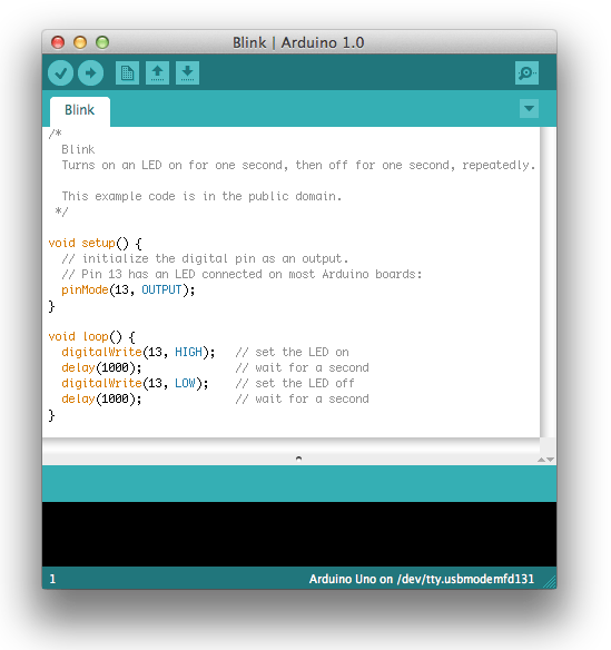
6 | Open the test program code
Open a test program that simply blinks the LED: File > Examples > 1.Basics > Blink.
7 | Select your Arduino model from the menu
Now on the menu Tools > Board you need to select the menu item corresponding to your Arduino model.
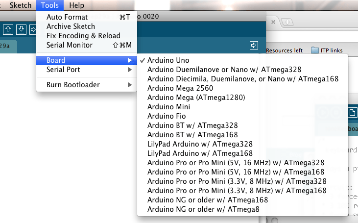
Selecting Arduino Uno
8 | Select Serial Port
On the menu Tools > Serial Port select the serial port your Arduino is connected to. As a rule, this is COM port number 3 ( COM3) or higher ( COM1 And COM2 usually associated with hardware ports). To find out the required port, you can temporarily disconnect the Arduino and open the menu again; the disappeared port will be the port with which your Arduino is associated. Reconnect the device to the computer and select the required port from the menu.
Help on Arduino language
In this article we will explain how to connect the Arduino Uno r3 driver and upload your first sketch. programmed using software - an integrated development environment common to all boards. It works both online and offline.
Driver Features for Arduino Uno
Arduino requires a driver to function fully on a computer. Installing driver software on Windows 7 is the easiest way to install software. It is best to download from a zipped file. This makes it easy to uninstall the software by deleting the folder.
When the Windows 10 operating system automatically installs the driver, the Arduino simply appears as a COM port in Device Manager. It is not recognized as a microprocessor, although it will work properly and code from the Arduino IDE can be loaded into it. After installing the Arduino Nano driver that comes with the Arduino software, the microcontroller will be shown as an Arduino on the COM port in Device Manager.
Types of drivers
There are several types of drivers for the Arduino motor and other projects based on this microcontroller. Let's look at several representatives of such software available for this microprocessor.
Type 1
Driver for the extended version of Arduino Uno - Arduino mega 2560 driver. Arduino Uno and Mega 2560 may have trouble connecting to Mac via USB hub. If in the menu " Tools → Serial Port"nothing is displayed, try connecting the board directly to the computer and restarting.
Disable digital pins 0 and 1 during boot as they are shared by serial communication with the computer (they can be connected and used after the code has been loaded). Arduino mega 2560 driver for Windows 7 is available at the following link: https://www.arduino.cc/en/Main/Software. After the transition, the user enters the name of the board into the search box of the official website of the microcontroller to download drivers.
Type 2
Avrisp mkii driver – required to create a programmer. When you install the USB driver is installed so you can use the Atmel AVRISP mk II programmer as an alternative to using the Arduino serial bootloader. Also, if you need to actually program the AVR MCU with the bootloader code itself (required if you have a bare Mega328 microprocessor that didn't have bootloader firmware pre-installed), you can do this from the Arduino IDE using Tools/Burn Bootloader.
After specifying AVRISP mk II as software using the Tools/Programmer function. However, when you install Studio 6.1/6.2, the Atmel installation will load its own USB driver that works with ID Studio.x. You have the option of not installing the Jungo driver during the Studio installation process, but you cannot use the Atmel AVRISP mk II or Atmel JTAGICE3 without this driver.
When you install the plugin Visual Micro for Studio 6.x You will most likely be using the Arduino serial bootloader since Visual Micro's programming and debugging capabilities are based on USB serial communication between the PC and the microcontroller. However, if you decide that you want to use the Atmel AVRISP mk II from the Visual Micro/Studio 6.x environment, you will find that it does not work. An error message will appear that AVRdude (the programming software used by the Arduino IDE) cannot “see” the AVRISP mk II programmer. This is because Studio6.x uses the Jungo USB driver rather than Visual.
Type 3
To construct a stepper motor you will need an Arduino l298n driver. This is a dual motor driver H-Bridge, which allows you to simultaneously control the speed and direction of two DC motors. The module can drive DC motors with voltages from 5 to 35 V with a peak current of up to 2A. Let's take a closer look at the L298N module pinout and explain how it works.
The module has two screw terminal pieces for motors A and B and another screw terminal block for the ground pin, VCC for the motor and a 5V pin which can be either input or output. This depends on the voltage used on the VCC motors. The module has a built-in 5V regulator, which is either enabled or disabled using a jumper.
If the motor supply voltage is up to 12V, we can turn on the 5V regulator, and the 5V pin can be used as an output, for example, to power the Arduino board. But if the motor voltage is more than 12V, we must disable the jumper because these voltages may damage the built-in 5V regulator.
In this case, the 5V pin will be used as the input signal since we need to connect it to a 5V power supply for the IC to work properly. It can be noted here that this IC reduces the voltage drop by about 2V. So for example, if we use a 12V power supply, the voltage at the motor terminals will be around 10V, which means that we will not be able to get maximum speed from our 12 volt DC motor.
Where and how to download the driver
All Arduino drivers are available on the official website: https://www.arduino.cc/. The user just needs to enter the driver needed for his project into the search.
Driver installation
Download the Arduino software and extract all the files into a folder c:\program. You will end up with a directory similar to arduino-0021.

Then connect the board to your computer using a USB cable and wait for Windows to detect the new device.
Windows won't be able to detect the device because it doesn't know where the drivers are stored. You will receive an error similar to the one on the right.
Select the option to install from a list or a specific location (Advanced) and click Next.

Now select the location where the Arduino drivers are stored. This will be in a subfolder called drivers in the Arduino directory.

Select Continue anyway.

Windows should now find the Arduino software. Click "Finish" to complete the installation.

The computer communicates with the board through a special serial port chip built into the board. The Arduino IDE software needs to know the serial port number that Windows has just allocated. Open the Windows Control Panel and select the system application. Go to the "Hardware" tab and then click the "Device Manager" button.
Click the Ports (COM and LPT) option and note which COM port has been allocated to the Arduino Board.

Then launch the Arduino IDE application, which will be located in the directory c:\program\arduino-0021 or similar.
Click " Service → Serial port" and select the port number from the top.

Then click Tools → Service and select the type of board you have.

Now try opening the Blink demo program from the examples directory in the Arduino IDE, Verify/Compile and download it to your platform.
This document explains how to connect your Arduino board to your computer and upload your first sketch.
Required hardware - Arduino and USB cable
This tutorial assumes you are using an Arduino Uno, Arduino Duemilanove, Nano or Diecimila.
You will also need a USB cable (with USB-A and USB-B connectors): such as, for example, to connect a USB printer. (For Arduino Nano you will need an A to mini-B cable instead).

Program - development environment for Arduino
Find the latest version on the download page.
After the download is complete, unzip the downloaded file. Make sure your folder structure is intact. Open the folder by double clicking on it. It should contain several files and subdirectories.
Connect the board
Arduino Uno, Mega, Duemilanove and Arduino Nano are powered automatically from any USB connection to your computer or other power source. If using an Arduino Diecimila, make sure the board is configured to receive power via a USB connection. The power source is selected using a small plastic jumper placed on two of the three pins between the USB and power connectors. Make sure it is installed on the two pins closest to the USB connector.
Connect the Arduino board to your computer using a USB cable. The green power LED labeled PWR should light up.
Install drivers
Installing drivers for Windows7, Vista or XP:
- Connect your board and wait for Windows to begin the driver installation process. After some time, despite all her attempts, the process will end in vain.
- Click on the START button and open Control Panel.
- In Control Panel, go to the System and Security tab. Then select System. When the System window opens, select Device Manager.
- Pay attention to the ports (COM and LPT). You will see an open port called "Arduino UNO (COMxx)".
- Right-click on the name “Arduino UNO (COMxx)” and select the “Update Driver Software” option.
- Click "Browse my computer for Driver software".
- To finish, locate and select the Uno driver file, “ArduinoUNO.inf,” located in the Drivers folder of the Arduino software (not in the “FTDI USB Drivers” subdirectory).
- At this point, Windows will finish installing the driver.
Select your serial port
Select the Arduino Serial Device from the Tools | Serial Port. This will probably be COM3 or higher (COM1 and COM2 are usually reserved for hardware COM ports). To find the correct port, you can disconnect the Arduino board and reopen the menu; The item that disappeared will be the Arduino board port. Reconnect the board and select the serial port.
Upload the sketch to Arduino
Now just click the “Upload” button in the program - the development environment. Wait a few seconds - you will see the RX and TX LEDs on the board blinking. If the upload is successful, the message “Done uploading” will appear in the status bar.
(Note: If you have an Arduino Mini, NG or other board, you need to physically issue the reset command with the button immediately before pressing the “Upload” button).
A few seconds after the boot is complete, you will see the pin 13 (L) LED on the board start blinking orange. Congratulations if so! You have received a ready-to-use Arduino!