Controlling the machine via WiFi using ESP8266 NodeMCU. Arduino Tank control via Wi-Fi
Good afternoon
Recently I became interested in the idea of creating “ smart home" Since from necessary components I currently only have an arduino and an Android phone at my disposal, so I decided to start by creating a control panel and connecting it with the rest of the system.
My vision of the system looks like this:
I think it’s worth combining home and web servers by purchasing a static IP address, but for the first time this will do. Let's start with something simple - learn how to remotely control an LED and LCD display.
Web-server
On the web server we create a database with two tables – leds and texts. The leds table contains 2 fields – id and status. It contains one entry with current state LED. The texts table contains 2 fields – id and text. It also contains one entry with text that at the moment displayed on the LCD display.Now let's write a couple of scripts that we will call from the phone and transmit information to the database. We write in php.
Script led.php (LED control):
Script msg.php (LCD display control):
I think it's clear from the comments how these scripts work. This is everything that resides on the web server. Now let's move on to the home server (or, more simply, the computer to which the Arduino is connected).
Home server
A program will constantly run on it (you can even call it a daemon), sending requests to the database and, when the information located there changes, sending the corresponding command to the COM port from the Arduino. Let's write the program in the Processing language:Import processing.serial.*; //library for working with COM port import de.bezier.data.sql.*; //library for working with the MySQL database Serial port; MySQL dbconnection; int prevLEDState = 0; // previous state LED String prevS = ""; //previous text sent to the LCD display void setup() ( port = new Serial(this, "COM4", 9600); //initialize COM port 4 (not attached to the arduino), baud rate - 9600 baud port. bufferUntil("\n"); String user = "user_name"; String pass = "database_name"; dbconnection = new MySQL(this, "your_domain.ru", database, user, pass); /connect to the database dbconnection.connect(); ) void draw() ( //monitor information about the LED in the database dbconnection.query("SELECT * FROM leds WHERE id = "1""); //make a query to the leds table while (dbconnection.next()) //bypass the selection from the query result ( int n = dbconnection.getInt("status"); //get the value from the status field if (n != prevLEDState) //if it has changed compared to the previous "cycle" of the program, then we send a command to the COM port ( prevLEDState = n; port.write("1"); //the first transmitted character will mean the code of the operation being performed: 1 - LED control, 2 - LCD display control port.write(n); ) ) //monitor information about the LCD display in the database dbconnection.query("SELECT * FROM texts WHERE id = "1""); //make a query to the texts table while (dbconnection.next())//bypass the selection from the query result ( String s = dbconnection.getString("text"); //get the value from the text field if (s != prevS) ( prevS = s; port.write("2"); port.write(s) ) delay(50); //make a delay of 50 ms so as not to send requests continuously)
I won’t explain this code either, everything is already clear.
1 more important point. So that a program from our computer can access a database located on remote server, this needs to be resolved. Enter our IP into the allowed list: 
Phone app
I have an Android phone, that’s what we’re writing for. I won’t go into too much detail (it’s very good about both installing the programming environment and writing the first application in this article - link).The appearance of the application looks rather modest, but in this case this is not the main thing: 
I will give only excerpts of the program code for Android. The function that calls the script that controls the LED:
public void changeLED() ( try ( URL url1 = new URL("http://your_domain.ru/led.php"); HttpURLConnection urlConnection = (HttpURLConnection) url1.openConnection(); try ( InputStream in = new BufferedInputStream(urlConnection .getInputStream()); ) finally ( urlConnection.disconnect(); ) ) catch (Exception e) ( ) )
Function that sends text to be displayed on the LCD display:
public void submitMsg() ( final EditText tt = (EditText) findViewById(R.id.editText1); try ( URL url1 = new URL("http://your_domain.ru/msg.php?msg="+tt.getText ());
Well main function, in which event handlers are bound to buttons:
public void onCreate(Bundle savedInstanceState) ( super.onCreate(savedInstanceState); setContentView(R.layout.main); final Button btn1 = (Button) findViewById(R.id.button1); btn1.setOnClickListener(new Button.OnClickListener() ( public void onClick(View v) // click on the button ( changeLED(); ) )); final Button btn2 = (Button) findViewById(R.id.button2); btn2.setOnClickListener(new Button.OnClickListener() ( public void onClick(View v) // click on the button ( submitMsg(); ) ));
And one more important point is to add permission for the application to access the Internet. To do this, you need to add the line to the AndroidManifest.xml file (it is located in the directory of our Android application):
Exporting our application to APK file and install it on your phone. Control panel smart home ready!
Arduino
And finally, last but not least, connecting the Arduino and flashing its firmware. The connection diagram for the LCD screen and LED to the Arduino Uno is as follows:
We take the resistor at 220 Ohms. You can read more about connecting an LCD screen here - link
And here's what it all looks like in reality: 
Isn't it beautiful?
The Arduino's job is to listen to what the daemon program is doing. home server sends to the COM port to which the Arduino is connected (although the actual connection is via a USB cable, but the computer recognizes it as a serial port). After receiving any data from the computer, the controller recognizes the command code from the first character of the transmitted information (i.e., what is now to be controlled - an LCD display or an LED). Then, depending on the code and the information following it, the LED is either turned on/off or the transmitted message is displayed. So here's the actual code:
#include
I think it doesn’t require any explanation, since I described everything in great detail in the comments. The only thing worth noting is some restrictions on the strings sent for display. They should not contain spaces (this limitation is imposed by the imperfection of my algorithm) and should not contain Cyrillic (since it is not supported by all displays, and if it is supported, it requires transmitting character codes in its own encoding, there is no way to convert characters into desires).
Conclusion
Well, that's all. It turned out to be quite simple.Video of how everything works:
Arduino boards and similar microcontrollers make creativity more accessible than ever, they write. Whether you're using it to automate your home or control LED strips, or even to protect your property, these amazing little pieces of tech are at the heart of most DIY electronic devices.
If you need to command your Arduino to change the position of a pin's jumpers (for example, turn on a light), then the Arduino will require the user to press a physical button or apply a sensor. For many projects, using human finger pressure or similar methods to control devices is fine, but what should you do if you just wanted to build a circuit that could be remotely accessed?
This article provides a brief description of six ways to connect your Android device to any compatible Arduino board.
1. ArduinoDroid allows you to create sketches
The first device on our list is ArduinoDroid. This application works via USB On The Go (OTG), connecting your mobile device to the Arduino via a USB cable. One of the advantages of a USB cable is that it does not require an Internet connection or Bluetooth for the device to function.
The application is a full-featured IDE that allows the user to write code on a smartphone, download previously written sketches that are stored in Dropbox or Google drive and then begin the compilation process.

The benefits of using the ArduinoDroid app are obvious. Having an IDE at your fingertips allows you to quickly make changes to fields, and the process of attaching an Android device is less complicated and time-consuming than trying to balance a bulky laptop in your arms!
The obvious disadvantage of the ArduinoDroid application is that writing code on your device may not be a very comfortable experience, especially if you use a smartphone for this purpose. At the same time, this weak point of the application is not so pronounced when on one side of the scale is the convenience of having an ultra-portable method of programming on your board at hand without the need for an Internet connection, and on the other side of the scale is the not very comfortable method of writing code .
On the other hand, having an ArduinoDroid is an inexpensive way to learn the basics of Arduino, since an Arduino board clone and USB On The Go cost a few dollars. For those who rarely have access to a computer, the ArduinoDroid app is a great alternative!
2. Arduino Bluetooth Controller
The next program on our list is the aptly named Arduino Bluetooth Controller. This application is of great importance in relation to triggers for changes in loaded sketches, and of less importance for Arduino programming. The Arduino Bluetooth controller sends data to your board via Bluetooth, giving you the ability to send serial data with the press of a button. You will need bluetooth module for your board, although the module HC-06 widely used and available for as little as $3.
Worth mentioning is the fact that the program is downloaded in English, although the Play Store pictures indicate Italian!
3. Blynk application for project development
The Blynk application is an excellent development for creating projects. The application's flexibility and simplicity provide an intuitive approach to triggering events on your board. Working with Blynk requires an Internet connection as the application uses its own server. You can use either Wi-Fi or mobile data to access the Blynk app, and this feature works great on smartphones.
One of the strongest points of the application is the variability of connections to the device. With support for almost all development boards, you can connect to the server wirelessly, or using ethernet and even a computer via USB. The service is well documented, and its intuitive application makes it easy to integrate customized control over your project. The Blynk library for the Arduino IDE monitors all communications.
If you prefer to turn on your coffee machine using your smartphone before getting out of bed early in the morning, this app is truly for you!
Blynk is not the only service in this category. It is also worth paying attention to such an extremely customized service as Thinger.io and the almost unlimited, albeit extremely difficult OpenHAB. Of the three services, Blynk is the fastest to get up and running, although learning OpenHAB is a great idea in the long run.
4. Communication from scratch
The applications described above rely on existing services that help you provide different connection options. What steps do you need to take to have complete and total control over every aspect of your Android apps? Why don't you solve this issue yourself and from scratch?
The problem of maintaining control over a package of applications is solved simply by opening USB connection and back-and-forth serial data transfer between applications and the Arduino board. This control option is one of the best for getting started with Android Studio and app creation in general.

It should be noted that if there are methods and methods for creating applications for devices on the Android platform without code, learning the basics of coding software in Java is also worth considering.
5. Turn your Arduino into a server
An alternative way to communicate with your board is to turn it into a tiny server. The key advantage of this transformation of the board into a server is the ability to communicate with the boards from any device that can navigate to an IP address or send a web request. This will require attachment Ethernet shield to your board to your home network.
If you don't have an Ethernet shield , then a similar effect can be achieved through a Wi-Fi shield or through a board connected to Wi-Fi, like NodeMCU.
If node.js code is your jam, it might make sense to take a look at the arduino-android github project. Once again, Android applications are developed based on open source, and all you need to do is install a node.js server on the Arduino board of your choice.

6. Infrared control
If you are looking for a universal communication tool with your Arduino or you would like to play the role of the legendary secret agent MacGyver, then remove infrared receiver(IT) from your old stereo or VHS player and use it to communicate with your Arduino board!
Transferring firmware, updates and other data using a soldering iron and wires is not the best solution for Arduino. However, microcontrollers for arduino wi-fi are not cheap, and they are not always needed, which is why users prefer not to use them in their projects unnecessarily.
But now another Chinese product has captured the market; you can connect your own wi-fi jammer esp8266 to an Arduino board or other system, and you will get a stable connection with a number of other advantages. So let’s figure out the arduino uno wi-fi, and whether it’s worth buying this module, as well as what a similar microcontroller on arduino wi-fi actually is.
Nowadays, most Arduino users no longer worry about the price of such devices, although 3 years ago an Arduino wi-fi module was considered a luxury. All this thanks to the wi-fi jammer esp8266, whose manufacturers introduced a completely new product to the market, amazing in its functionality and, at the same time, being quite cheap, which made a significant contribution and created competition in this direction.
Thus, arduino wi-fi esp8266 is now considered the most affordable module on the market, like all its brothers. Thus, the price on foreign sites starts from 2 dollars, which allows you to purchase these modules in batches and not have to reflash them a thousand times, resoldering the contacts in order to maintain functionality.

At first, this Arduino wi-fi module was used mainly as an arduino wi-fi shield, since it was the cheapest option and was in no way inferior to the original one. The device is truly almost legendary, because there are no significant disadvantages for its price. There are many libraries, including user ones, and also supports work via Serial buses and the simplest AT and AT+ commands. Thanks to this, there is no need to study any semantics of the notorious C99, as is often the case with other third-party microcontrollers.
Accordingly, even a beginner will figure it out in seconds, and a professional will be able to use already prepared libraries. Other advantages include:
- The processor is 160 MHz, but it is 32-bit, which leaves a certain imprint on performance. But it’s worth remembering that the module is still used in conjunction with Arduino boards, which themselves cut high frequencies and eat up most of the resources for unknown reasons.
- The manufacturer that released the esp8266 wi-fi module did not stop interesting projects, and now there is a whole line of microcontrollers of proven quality.
- Modern network security standards. Of course, WPA and WPA2 are no longer as secure as we would like, but their presence cannot but please us in such a cheap controller.
- 16 output ports, including 10-bit, allowing you to experiment with the board.
More importantly, out of the box you will find up to 4 megabytes of permanent memory, depending on the type of board, and this greatly simplifies working with large libraries and even some media files. After all, on most Arduino boards even 1 megabyte is considered an unaffordable luxury.
The characteristics of the esp8266 wi-fi are certainly encouraging, especially in comparison with its more expensive competitors, but a user who has no previous experience with these boards will have a question about how to connect it. The fact is that the module has many more pins than beginners are used to seeing, and, accordingly, they begin to panic. However, if you understand the situation, then in reality there is nothing complicated about it. It is enough to stock up on solder and a soldering iron and just read the instructions.
How to connect a Wi-Fi module to Arduino
Let's look at connecting the esp8266 esp 12e and what an esp8266 wi-fi uart bridge is. After all, it is the connection and configuration of the module that raises the most questions.

First of all, decide which version of the microcontroller you have. In the first, LEDs are built in near the pins, and in the second, which began to be produced quite recently, the signal lights are located near the antenna.
Before connecting, you should download the latest firmware, which allows you to increase the packet exchange rate to 9600 units of information per second. And we will check the connection using a usb-ttl cable and the corresponding terminal from CoolTerm.

The pins for connecting the cable described above are standard, but the power comes through a 3.3 volt pin from the Arduino. It is important to remember that the maximum current supplied by the board cannot be set above 150 mA, and esp8266 esp 07 and esp8266 witty cloud wi-fi module for arduino require 240 mA.
However, if there is no other current source, you can use the standard version from Arduino, but the power of the board will suffer. Although, if the load is not heavy, 70 mA is enough, be prepared for sudden reboots of the microcontroller at peak load times and write software accordingly so that it filters and splits files without overloading the board.

Another connection option is below. Important - the RX-TX contacts are connected with a crosshair. Since the signal levels of the ESP8266 module are 3.3V, and the Arduino is 5V, we need to use a resistive voltage divider to convert the signal level.

Registering a Wi-Fi module in Arduino
As you know, with proper experience, you can pair the esp8266 ex 12e shield with a smartphone, but for beginners, registering the esp8266 esp 12 in the Arduino system causes difficulties. In fact, it is enough to connect the module and check its functionality by issuing several standard AT commands through the debug menu.
For example, you can add blinking with a standard LED (for the connection diagram above):
#define TXD 1 // GPIO1/TXD01 void setup() ( pinMode(TXD, OUTPUT); ) void loop() ( digitalWrite(TXD, HIGH); delay(1000); digitalWrite(TXD, LOW); delay(1000) ; )
As soon as the board confirms that it sees the microcontroller in the system, you can begin full work with it. However, it is worth noting that if the Arduino board itself is used in the project only to connect this controller, this is irrational.
A USB-UART converter is sufficient, since the esp8266 does not use the “brains” of the Arduino, and its flash memory is quite enough for storing a couple of basic libraries and firmware. Accordingly, there is no point in spending extra money on an auxiliary board if you can simply solder it to the converter and further use it in the project. At the same time, by connecting an auxiliary power source and without worrying that data will stop being transmitted at the most crucial moment due to a lack of system power.
Important note! For the last circuit, we upload the sketch to the Arduino as usual, but since the ESP8266 module is connected to pins 0 and 1, programming becomes impossible. The compiler will show an error. Disconnect the wires going to the ESP8266 from pins 0 and 1, do the programming, and then return the pins to their place and press the reset button on the Arduino.
With Wi-Fi module.
The Arduino Uno WiFi provides everything for convenient work with the microcontroller: 14 digital inputs/outputs (6 of them can be used as PWM outputs), 6 analog inputs, a USB connector, a power connector, an in-circuit programming connector (ICSP) and a reset button microcontroller.
The highlight of the board is the ESP8266 WiFi module, which allows Arduino to exchange information with other modules via 802.11 b/g/n wireless networks.
ESP8266 allows you to flash an Arduino board without using a USB cable in OTA (Firmware Over The Air) mode.
Video review of the board
Connection and setup
To get started with the Arduino Uno WiFi board in the Windows operating system, download and install the Arduino integrated development environment - Arduino IDE - on your computer.
Did something go wrong?
Setting up the WiFi module
Arduino firmware via WiFi
Arduino Uno WiFi has another nice bonus - the ability to upload sketches without using a USB cable in OTA (Firmware Over The Air) mode. Let's take a closer look at how to do this.

To do this you need to enter the menu: Tools Port and select the desired port.
Since we are flashing the Arduino via WiFi, the board will be identified as a remote device with an IP address

The environment is configured, the board is connected. You can proceed to uploading the sketch. Arduino IDE contains a large list of ready-made examples in which you can see the solution to any problem. Let's choose among the examples of LED blinking - the “Blink” sketch.  Flash the board by clicking on the program download icon.
  After booting, the LED will start flashing once per second. This means that everything worked out.
Now you can move on to examples of use.
Examples of use
Web server
Let's set up a simple web server that will display a page with the current values of the analog inputs.
web-server.ino /* An example of a simple web server running on Arduino Uno WiFi. The server displays the values on the analog inputs and updates the information every two seconds. Contact the server at http://Example of outputting values from analog pins
" ) ; client.print("- " ); for (int analogChannel = 0 ; analogChannel<
4
;
analogChannel++
)
{
int
sensorReading =
analogRead(analogChannel)
;
client.print
("
- on the analog input" ) ; client.print(analogChannel) ; client.print(": " ) ; client.print (sensorReading) ; client.print ("" ) ; ) client.println ( "
Board elements

Microcontroller ATmega328P
The heart of the Arduino Uno WiFi platform is the 8-bit microcontroller of the AVR family - ATmega328P.
Microcontroller ATmega16U2
The ATmega16U2 microcontroller provides communication between the ATmega328P microcontroller and the USB port of the computer. When connected to a PC, the Arduino Uno WiFi is detected as a virtual COM port. The 16U2 chip's firmware uses standard USB-COM drivers, so no external driver installation is required.
Power pins
VIN: Voltage from external power supply (not related to 5V from USB or other regulated voltage). Through this pin you can both supply external power and consume current if an external adapter is connected to the device.
5V: The pin receives a voltage of 5 V from the board's stabilizer. This stabilizer provides power to the ATmega328 microcontroller. It is not recommended to power the device through the 5V pin - in this case, a voltage stabilizer is not used, which can lead to board failure.
3.3V: 3.3 V from the board stabilizer. The maximum output current is 1 A.
GND: Conclusions of the earth.
IOREF: The pin provides expansion boards with information about the operating voltage of the microcontroller. Depending on the voltage, the expansion board can switch to the appropriate power supply or use level converters, allowing it to work with both 5V and 3.3V devices.
I/O Ports
Digital inputs/outputs: pins 0 – 13
The logical level of one is 5 V, zero is 0 V. The maximum output current is 40 mA. Pull-up resistors are connected to the contacts, which are disabled by default, but can be enabled by software.
PWM: pins 3, 5, 6, 9, 10 and 11
Allows you to output 8-bit analog values as a PWM signal.
ADC: pins A0 – A5
6 analog inputs, each of which can represent analog voltage as a 10-bit number (1024 values). The ADC capacity is 10 bits.
TWI/I²C: SDA and SCL pins
For communication with peripherals using a synchronous protocol, via 2 wires. To work, use the Wire library.
SPI: pins 10(SS), 11(MOSI), 12(MISO), 13(SCK).
Through these pins, communication via the SPI interface is carried out. To work, use the SPI library.
UART: pins 0(RX) and 1(TX)
These pins are connected to the corresponding pins of the ATmega16U2 microcontroller, which acts as a USB-UART converter. Used to communicate between the Arduino board and a computer or other devices via the Serial class.
LED indication
USB Type-B connector
The USB Type-B connector is designed for flashing the Arduino Uno WiFi platform using a computer.
External power connector
Connector for connecting external power from 7 V to 12 V.
5V voltage regulator
When the board is connected to an external power source, the voltage passes through the MPM3610 regulator. The stabilizer output is connected to the 5V pin. The maximum output current is 1A.
3.3V voltage regulator
Stabilizer MPM3810GQB-33 with 3.3 volt output. Provides power to the ESP8266 WiFi module and is output to the 3.3V pin. The maximum output current is 1A.
ICSP connector for ATmega328P
The ICSP connector is designed for in-circuit programming of the ATmega328P microcontroller. Using the SPI library, these pins can communicate with expansion boards via the SPI interface. The SPI lines are routed to a 6-pin connector, and are also duplicated on digital pins 10(SS), 11(MOSI), 12(MISO) and 13(SCK).
ICSP connector for ATmega16U2
The ICSP connector is designed for in-circuit programming of the ATmega16U2 microcontroller.
The ESP8266 chip is one of the most popular tools for organizing wireless communications in smart home projects. Using a wireless controller, you can organize communication via the WiFi interface, providing Arduino projects with Internet access and the ability to remotely control and collect data. Such popular boards as WeMos and NodeMcu, as well as a huge number of homemade projects, have been created based on the ESP8266. In this article, we will find out what the ESP82266 is, what its varieties are, and how to work with the ESP8266 in the Arduino IDE.
ESP8266 is a microcontroller with a WiFi interface that has the ability to execute programs from flash memory. The device was released in 2014 by the Chinese company Espressif and almost immediately became popular.
The controller is inexpensive, has a small number of external elements and has the following technical parameters:
- Supports Wi-Fi protocols 802.11 b/g/n with WEP, WPA, WPA2;
- Has 14 input and output ports, SPI, I2C, UART, 10-bit ADC;
- Supports external memory up to 16 MB;
- Required power supply is from 2.2 to 3.6 V, current consumption is up to 300 mA, depending on the selected mode.
An important feature is the absence of user non-volatile memory on the chip. The program is executed from an external SPI ROM using dynamic loading of the necessary program elements. Access to the internal peripherals can be obtained not from the documentation, but from the API of a set of libraries. The manufacturer indicates the approximate amount of RAM - 50 kB.
Features of the ESP8266 board:
- Convenient connection to a computer - via a USB cable, powered by it;
- Availability of built-in 3.3V voltage converter;
- Availability of 4 MB flash memory;
- Built-in buttons for rebooting and flashing;
- All ports are routed onto the board using two combs with a pitch of 2.5 mm.
Areas of application of the ESP8266 module
- Automation;
- Various systems for a smart home: Wireless control, wireless sockets, temperature control, addition to alarm systems;
- Mobile electronics;
- Tag ID;
- Children's toys;
- Mesh networks.
esp8266 pinout
There are a huge number of varieties of the ESP8266 module. The figure shows some of them. The most popular option is ESP 01.

The execution of the program must be determined by the state of the GPIO0, GPIO2 and GPIO15 ports when the power supply ends. Two important modes can be distinguished - when the code is executed from the UART (GPIO0 = 0, GPIO2 = 1 and GPIO15 = 0) for flashing a flash card and when it is executed from an external ROM (GPIO0 = 1, GPIO2 = 1 and GPIO15 = 0) in the standard mode.
The pinout for ESP01 is shown in the picture.
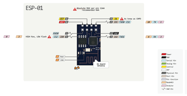

Contact description:
- 1 – ground, 8 – power. According to the documentation, the voltage is supplied up to 3.6 V - this is important to take into account when working with Arduino, which is usually supplied with 5 V.
- 6 – RST, needed to reboot the microcontroller when a low logic level is applied to it.
- 4 – CP_PD, also used to put the device into energy saving mode.
- 7 and 0 – RXD0 and TXD0, this is a hardware UART required for flashing the module.
- 2 – TXD0, an LED is connected to this pin, which lights up when the logic level on GPIO1 is low and when data is transmitted via UART.
- 5 – GPIO0, input and output port, also allows you to put the device into programming mode (when the port is connected to a low logic level and voltage is applied).
- 3 – GPIO2, input and output port.
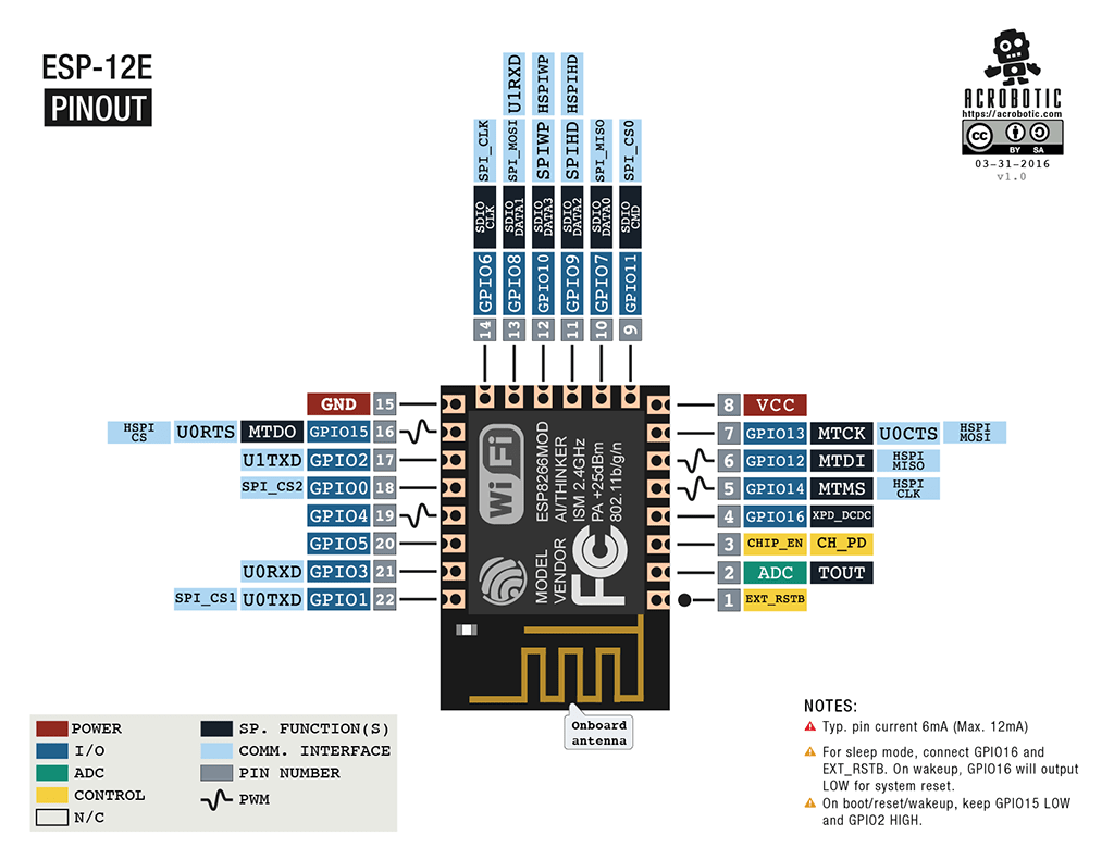
ESP-12 pinout
The main differences between Arduino and ESP8266
- The ESP8266 has a larger amount of flash memory, while the ESP8266 does not have non-volatile memory;
- ESP8266 processor is faster than Arduino;
- ESP8266 has Wi-Fi;
- ESP8266 consumes more current than Arduino;
Programming ESP8266 in Arduino IDE
The esp8266 development kit includes:
- Compiler from the GNU Compiler Collection.
- Libraries, WiFi, TCP/IP protocol stacks.
- A means of loading information into the controller program.
- Operating IDE.
Initially, ESP8266 modules are supplied with firmware from the manufacturer. With its help, you can control the module from an external microcontroller and work with Wi-Fi as a modem. There are also many other ready-made firmwares. Some of them allow you to configure the module’s operation using a WEB interface.
Can be programmed from the Arduino IDE. With its help, you can easily write sketches and upload them to the ESP8266, flash the ESP8266, and do not require the Arduino board itself. Arduino IDE supports all kinds of ESP8266 modules.
Currently, the following functions can be implemented for the ESP8266:
- Basic functions of the Wiring language. You can control the GPIO ports in the same way as the pins on the Arduino board: pinMode, digitalRead, digitalWrite, analogWrite. The analogRead(A0) command allows you to read ADC values. Using the analogWrite (pin, value) command, you can connect PWM to the desired GPIO output. When value=0, PWM is disabled, the maximum value reaches a constant equal to 1023. Using the attachInterrupt and detachInterrupt functions, you can interrupt on any GPIO port except 16.
- Timing and delay. Using the millis and micros commands you can return the ms and μs that have passed since the start. Delay allows you to pause program execution for the desired time. Also, the delay(…) function allows you to maintain normal Wi-Fi operation if the sketch contains large elements that take more than 50 ms to execute. Yield() is an analogue of the delay(0) function.
- Serial and Serial1 (UART0 and UART1). Serial work on ESP8266 is similar to work on Arduino. Writing and reading data blocks code execution if the 128-byte FIFO and 256-byte software buffer are full. The Serial object uses hardware UART0, you can set pins GPIO15 (TX) and GPIO13 (RX) for it instead of GPIO1(TX) and GPIO3(RX). To do this, after the Serial.begin(); you need to call Serial.swap();. Similarly, Serial1 uses UART1, which works for transmission. The required pin for this is GPIO2.
- Macro PROGMEM. Its operation is similar to that of Arduino. Allows you to move read only data and string constants into flash memory. At the same time, the ESP8266 does not store the same constants, which leads to additional waste of flash memory.
- I2C. Before working with the I2C bus, the buses are selected using the Wire.pins(int sda, int scl) function.
- SPI, OneWire – fully supported.
Using esp8266 to communicate with Arduino via WiFi
Before connecting to Arduino, it is important to remember that the supply voltage of the ESP8266 cannot be higher than 3.6, while on the Arduino the voltage is 5 V. You need to connect 2 microcontrollers using resistive dividers. Before connecting the module, you need to familiarize yourself with the pinout of the selected ESP8266. The connection diagram for ESP8266-01 is shown in the figure.
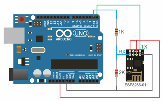
3.3 V from Arduino to Vcc&CH_PD on the ESP8266 module, Ground from Arduino to ground from ESP8266, 0 – TX, 1 – RX.
To maintain stable operation, the ESP8266 requires a 3.3V constant voltage source and a maximum current of 250mA. If the power comes from a USB-TTL converter, malfunctions and malfunctions may occur.
Working with the Wi-Fi library for the ESP8266 is similar to the library for a regular shield. There are several features:
- mode(m) – to select one of three modes: client, access point, or both modes at the same time.
- softAP(ssid) – needed to create an open access point.
- softAP(ssid, password) – creates an access point with a password, which must consist of at least 8 characters.
- WiFi.macAddress(mac) and WiFi.softAPmacAddress(mac) – defines the MAC address.
- WiFi.localIP() and WiFi.softAPIP() – determining the IP address.
- printDiag(Serial); – will allow you to find out diagnostic data.
- WiFiUDP – support for sending and receiving multicast packets in client mode.
The work is performed according to the following algorithm:
- Connecting USB-TTL to USB and to ESP.
- Launching Arduino IDE.
- Select the required port, board, frequency and flash memory size in the tools menu.
- File - Examples - ESP8266WiFi - WiFiWebServer.
- Write down the SSID and password of the Wi-Fi network in the sketch.
- Start compiling and uploading code.
- Wait for the firmware process to finish, disconnect GPIO0 from ground.
- Set the speed to 115200.
- A connection will occur and the IP address will be recorded.
- Open a browser, enter the IP/gpio/1 number in the address bar
- Look at the port monitor; if an LED is connected to the GPIO2 output, it should light up.
NodeMCU based on esp8266
 NodeMCU is a platform based on the esp8266 module. Used to control the circuit remotely using the Internet via Wi-Fi. The board is small-sized, compact, inexpensive, and has a USB connector on the front side. Nearby are buttons for debugging and rebooting the microcontroller. An ESP8266 chip is also installed. Supply voltage is from 5 to 12 V, it is advisable to supply more than 10 V.
The board's big advantage is its low power consumption. They are often used in self-powered circuits. There are only 11 general purpose ports on the board, some of which have special functions:
- D1 and D2 – for I2C/ TWI interface;
- D5-D8 - for SPI interface;
- D9, D10 – for UART;
- D1-D10 – can work as PWM.
The platform has a modern API for hardware input and output. This allows you to reduce the number of steps when working with equipment and when setting it up. With the help of NodeMCU firmware, you can use the full operational potential for rapid device development.
WeMos based on esp8266
 WeMos is another type of platform based on the esp8266 microcontroller. Accordingly, there is a Wi-Fi module, Arduino IDE is supported, and there is a connector for an external antenna. The board has 11 digital inputs/outputs, which (except D0) support interrupt/pwm/I2C/one-wire. The maximum supply voltage reaches 3.3 V. There is also a USB connector on the platform. Analog input 1 with a maximum voltage of 3.2V.
To work with the module, you need to install the CH340 driver and configure the Arduino IDE for the ESP8266. To do this, you need to add the address http://arduino.esp8266.com/stable/package_esp8266com_index.json in the settings menu in the “additional link for board manager” line.
After this, you need to find the esp8266 by ESP8266 package and install it. Then you need to select the Wemos D1 R2 microcontroller from the tools menu and write down the desired sketch.
Conclusions on ESP8266
With boards based on the ESP8266 chip, you can add Big Internet capabilities to your projects, making them much more intelligent. Remote control, data collection and analysis on the server, voice processing and image processing - all this becomes available when we connect our project via WiFi to the Internet. In the following articles, we will take a closer look at how you can program esp8266-based devices, and also pay attention to such popular boards as WeMos and NodeMcu.