The simplest sound amplifier with one transistor. The best quality sound amplifier
Circuit of a simple transistor audio amplifier, which is implemented on two powerful composite transistors TIP142-TIP147 installed in the output stage, two low-power BC556B in the differential path and one BD241C in the signal pre-amplification circuit - a total of five transistors for the entire circuit! This design of the UMZCH can be freely used, for example, as part of a home music center or to drive a subwoofer installed in a car or at a disco.
The main attractiveness of this audio power amplifier lies in the ease of its assembly even by novice radio amateurs; there is no need for any special configuration, and there are no problems in purchasing components at an affordable price. The PA circuit presented here has electrical characteristics with high linearity of operation in the frequency range from 20Hz to 20000Hz. p>
When choosing or independently manufacturing a transformer for a power supply, you need to take into account the following factor: - the transformer must have a sufficient power reserve, for example: 300 W per one channel, in the case of a two-channel version, then naturally the power doubles. You can use a separate transformer for each, and if you use a stereo version of the amplifier, then you will generally get a “dual mono” type device, which will naturally increase the efficiency of sound amplification.
The effective voltage in the secondary windings of the transformer should be ~34v AC, then the constant voltage after the rectifier will be in the region of 48v - 50v. In each power supply arm, it is necessary to install a fuse designed for an operating current of 6A, respectively, for stereo when operating on one power supply - 12A.
Evgenia Smirnova
To send light into the depths of the human heart - this is the purpose of the artist
Content
Connecting speakers to a laptop, TV, or other music source sometimes requires amplification of the signal using a separate device. The idea of building your own amplifier is a good one if you are inclined to work with printed circuit boards at home and have some technical skills.
How to make a sound amplifier
The beginning of work on assembling an amplification device for speakers of one type or another consists of searching for tools and components. The amplifier circuit is assembled on a printed circuit board using a soldering iron on a heat-resistant support. It is recommended to use special soldering stations. If you assemble it yourself for the purpose of testing the circuit or for use for a short period of time, the “on wires” option is suitable, but you will need more space to place the components. The printed circuit board guarantees the compactness of the device and ease of further use.
A cheap and widespread amplifier for headphones or small speakers is created on the basis of a microcircuit - a miniature control unit with a pre-wired set of commands for controlling an electrical signal. All that remains to be added to the circuit with the microcircuit is a few resistors and capacitors. The total cost of an amateur-grade amplifier is ultimately significantly lower than the price of ready-made professional equipment from the nearest store, but the functionality is limited to changing the output volume of the audio signal.

Remember the features of compact single-channel amplifiers that you assemble yourself based on TDA series microcircuits and their analogues. The microcircuit generates a large amount of heat during operation, so you should eliminate or minimize its contact with other parts of the device. A radiator grille for heat dissipation is recommended for use. Depending on the model of the microcircuit and the power of the amplifier, the size of the required heatsink increases. If the amplifier is assembled in a housing, you should first plan a place for the heat sink.
Another feature of assembling a sound amplifier with your own hands is the low voltage consumption. This allows you to use a simple amplifier in cars (powered by a car battery), on the road or at home (powered by a special unit or batteries). Some simplified audio amplifiers require a voltage of only 3 Volts. Power consumption depends on the degree of audio signal amplification required. The sound amplifier from the player for standard headphones consumes about 3 Watts.
It is recommended that a novice radio amateur use a computer program to create and view circuit diagrams. Files for such programs can have a *.lay extension - they are created and edited in the popular virtual tool Sprint Layout. Creating a circuit with your own hands from scratch makes sense if you have already gained experience and want to experiment with the knowledge you have gained. Otherwise, look for and download ready-made files that can be used to quickly assemble a replacement for a low-frequency amplifier for a car radio or a digital combo amplifier for a guitar.

For laptop
A do-it-yourself sound amplifier for a laptop is assembled in one of two cases: the built-in speakers are out of order, or their volume and sound quality are not enough for your needs. You will need a simple amplifier designed for a power of external speakers up to 2 Watts, and a winding resistance of up to 4 Ohms. To assemble it yourself, in addition to standard amateur radio tools (pliers, soldering station), you will need a printed circuit board, a TDA 7231 microcircuit, and a 9-volt power supply. Select your own housing to house the amplifier components.
Add the following items to the list of purchased components:
- non-polar capacitor 0.1 µF – 2 pcs.;
- polar capacitor 100 µF – 1 pc.;
- polar capacitor 220 µF – 1 pc.;
- polar capacitor 470 µF – 1 pc.;
- constant resistor 10 KOhm – 1 pc.;
- constant resistor 4.7 Ohm – 1 pc.;
- two-position switch – 1 pc.;
- jack for loudspeaker output – 1 pc.
Determine the assembly order yourself depending on which *.lay electrical diagram you downloaded. Select a radiator of such a size that its thermal conductivity allows you to maintain the operating temperature of the microcircuit below 50 degrees Celsius. If the device is constantly used outdoors with a laptop, it will need a homemade case with slots or holes for air circulation. You can assemble such a case with your own hands from a plastic container or the remains of old radio equipment, securing the board with long screws.

For DIY headphones
The simplest stereo amplifier for portable headphones should have low power, but the most important parameter will be power consumption. In an ideal example, the design is powered by AA batteries, or, in extreme cases, by a simple 3-volt adapter. You will need a high-quality TDA 2822 microcircuit or its analogue (for example, KA 2209), an electronic circuit for assembling an amplifier with your own hands using a TDA 2822. Additionally, take the following components:
- capacitors 100 µF (4 pcs.);
- up to 30 cm of copper wire;
- headphone socket.
A heat sink element will be needed if you want to make the amplifier compact and with a closed housing. The amplifier can be assembled on a ready-made or home-made printed circuit board or by surface mounting. The pulse transformer in the power supply may cause interference, so do not use it in this amplifier. The finished amplifier will provide pleasant and powerful sound from the player (record or radio signal), tablet or phone.

Subwoofer amplifier circuit
The low-frequency amplifier is assembled with your own hands on the TDA 7294 microcircuit. It is used both to create powerful acoustics with bass in the apartment, and as a car amplifier - in this case, however, you need to purchase a bipolar power supply of 30-35 Volts. The figures below describe the location of components, as well as the values of resistors and capacitors. This subwoofer amplifier will provide an output power of up to 100 watts with outstanding low frequencies.

Mini sound amplifier for speakers
The design described above for laptops is suitable as a sound amplification device for domestic or foreign home speakers. Stationary placement of the device will allow you to choose any power adapter from those available. You can ensure the miniature size and acceptable appearance of an inexpensive amplifier by following several rules:
- Ready-made high-quality printed circuit board.
- Durable plastic or metal case (order from a specialist).
- The placement of components is pre-planned.
- The amplifier is soldered neatly, without unnecessary drops of solder.
- The heatsink only touches the chip.
- Ready-made sockets are used for signal output and power input.

DIY tube sound amplifier
Tube sound amplifiers are expensive devices, provided that you purchase all the components at your own expense. Old radio amateurs sometimes keep collections of tubes and other parts. Assembling a tube amplifier at home with your own hands is relatively easy if you are willing to spend a few days searching for detailed circuit diagrams on the Internet. The sound amplifier circuit in each case is unique and depends on the sound source (old tape recorder, modern digital equipment), power source, expected dimensions and other parameters.
Transistor sound amplifier
Assembling a sound preamplifier with your own hands without using complex microcircuits is possible using transistors. An amplifier based on germanium transistors can be easily integrated into modern audio systems; it does not require additional configuration. The disadvantage of transistor circuits is the larger size of the board assembly. The dependence on the “purity” of the background is also unpleasant - you will need a shielded cable, or an additional circuit for suppressing noise and ripple from the network.
Video: DIY audio power amplifier
Found an error in the text? Select it, press Ctrl + Enter and we will fix everything!There was a desire to assemble a more powerful Class A amplifier. After reading a sufficient amount of relevant literature, I chose the latest version from what was offered. It was a 30 W amplifier corresponding in its parameters to high-class amplifiers.
I did not intend to make any changes to the existing routing of the original printed circuit boards, however, due to the lack of original power transistors, a more reliable output stage was chosen using 2SA1943 and 2SC5200 transistors. The use of these transistors ultimately made it possible to provide greater output power to the amplifier. The schematic diagram of my version of the amplifier is below.

This is an image of boards assembled according to this circuit with Toshiba 2SA1943 and 2SC5200 transistors.

If you look closely, you can see on the printed circuit board along with all the components there are bias resistors, they are 1 W carbon type. It turned out that they are more thermostable. When any high-power amplifier operates, a huge amount of heat is generated, so maintaining a constant rating of the electronic component when heating it is an important condition for the high-quality operation of the device.

The assembled version of the amplifier operates at a current of about 1.6 A and a voltage of 35 V. As a result, 60 W of continuous power is dissipated on the transistors in the output stage. I should note that this is only a third of the power they can handle. Try to imagine how much heat is generated on the radiators when they are heated to 40 degrees.

The amplifier case is made by hand from aluminum. Top plate and mounting plate 3mm thick. The radiator consists of two parts, its overall dimensions are 420 x 180 x 35 mm. Fasteners - screws, mostly with a countersunk stainless steel head and M5 or M3 thread. The number of capacitors was increased to six, their total capacity is 220,000 µF. A 500 W toroidal transformer was used for power supply.

Amplifier power supply
The amplifier device, which has copper busbars of the appropriate design, is clearly visible. A small toroid is added for controlled flow under the control of a DC protection circuit. There is also a high-pass filter in the power supply circuit. For all its simplicity, it must be said deceptive simplicity, the board topology of this amplifier produces sound as if without any effort, implying in turn the possibility of its infinite amplification.
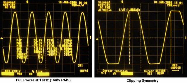
Oscillograms of amplifier operation
3 dB roll-off at 208 kHz
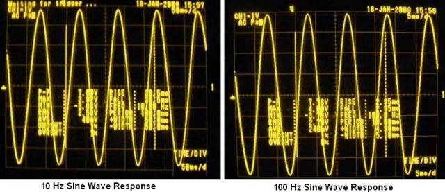
Sine wave 10 Hz and 100 Hz

Sine wave 1 kHz and 10 kHz
100 kHz and 1 MHz signals

Square wave 10 Hz and 100 Hz

Square wave 1 kHz and 10 kHz

60 W total power, 1 kHz symmetry cutoff

Thus, it becomes clear that a simple and high-quality design of an UMZCH is not necessarily made using integrated circuits - only 8 transistors allow you to achieve decent sound with a circuit that can be assembled in half a day.
They are becoming a thing of the past, and now, in order to assemble any simple amplifier, you no longer have to struggle with calculations and rivet a large printed circuit board.
Now almost all cheap amplification equipment is made on microcircuits. The most widespread are TDA chips for amplifying audio signals. Currently used in car radios, powered subwoofers, home speakers and many other audio amplifiers, they look something like this:


Pros of TDA chips
- In order to assemble an amplifier on them, it is enough to supply power, connect speakers and several radio elements.
- The dimensions of these microcircuits are quite small, but they will need to be placed on a radiator, otherwise they will get very hot.
- They are sold at any radio store. There are some things on Ali that are a little expensive if you buy them at retail.
- They have built-in various protections and other options, such as muting the sound, etc. But according to my observations, the protections do not work very well, so microcircuits often die either from overheating or from. So it is advisable not to short-circuit the pins of the microcircuit with each other and not to overheat the microcircuit, squeezing all the juices out of it.
- Price. I wouldn't say they are very expensive. In terms of price and functions, they have no equal.
Single-channel amplifier on TDA7396
Let's build a simple single-channel amplifier using the TDA7396 chip. At the time of writing, I took it at a price of 240 rubles. The datasheet for the chip said that this chip can output up to 45 Watts into a 2 Ohm load. That is, if you measure the resistance of the speaker coil and it is about 2 ohms, then it is quite possible to get a peak power of 45 watts from the speaker.This power is quite enough to arrange a disco in the room not only for yourself, but also for your neighbors and at the same time get mediocre sound, which, of course, cannot be compared with hi-fi amplifiers.
Here is the pinout of the microcircuit:

We will assemble our amplifier according to a typical diagram, which was attached in the datasheet itself:

We apply +Vs to leg 8, and nothing to leg 4. Therefore, the diagram will look like this:

Vs is the supply voltage. It can be from 8 to 18 Volts. “IN+” and “IN-” – we send a weak sound signal here. We attach a speaker to the 5th and 7th legs. We set the sixth leg to minus.
Here is my wall mounted assembly

I did not use capacitors at the power input of 100nF and 1000uF, since I already have pure voltage coming from the power supply.
I rocked the speaker with the following parameters:

As you can see, the coil resistance is 4 ohms. The frequency band indicates that it is a subwoofer type.
And this is what my sub in a self-made housing looks like:

I tried to take a video, but the sound on the video is very poor. But I can still say that the phone at medium power was already hammering so hard that my ears were turning, although the consumption of the entire circuit in working form was only about 10 watts (multiply 14.3 by 0.73). In this example, I took the voltage as in a car, that is, 14.4 Volts, which is well within our operating range from 8 to 18 Volts.

If you do not have a powerful power source, then you can assemble it according to this diagram.
Don't get hung up on this particular chip. These TDA chips, as I already said, there are many types. Some of them amplify the stereo signal and can output sound to 4 speakers at once, as is done in car radios. So don’t be lazy to scour the Internet and find a suitable TDA. After completing the assembly, let your neighbors check out your amplifier by turning the volume knob all the way to the balalaika and leaning the powerful speaker against the wall).
But in the article I assembled an amplifier using a TDA2030A chip

It turned out very well, since the TDA2030A has better characteristics than the TDA7396
For variety, I’ll also attach another diagram from a subscriber whose TDA 1557Q amplifier has been working properly for more than 10 years in a row:

Amplifiers on Aliexpress
I also found kit kits on Ali on TDA. For example, this stereo amplifier is 15 watts per channel and costs $1. This power is quite enough to hang out in your room listening to your favorite tracks.

You can buy it.
And here it's ready right away

And in general, there are a lot of these amplifier modules on Aliexpress. Click on this link and choose any amplifier you like.
Recently, a certain person asked me to build him an amplifier of sufficient power and separate amplification channels for low, medium and high frequencies. Before this I had already collected it more than once for myself as an experiment and, I must say, the experiments were very successful. The sound quality of even inexpensive speakers of a not very high level is noticeably improved compared, for example, with the option of using passive filters in the speakers themselves. In addition, it becomes possible to quite easily change the crossover frequencies and the gain of each individual band and, thus, it is easier to achieve a uniform frequency response of the entire sound amplification path. The amplifier used ready-made circuits that had previously been tested more than once in simpler designs.
Structural scheme
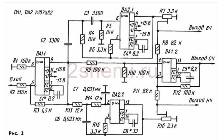
The figure below shows the circuit diagram of channel 1:

As can be seen from the diagram, the amplifier has three inputs, one of which provides a simple possibility of adding a preamplifier-corrector for a vinyl player (if necessary), an input switch, a pre-amplifier-tone control (also three-band, with adjustable HF/MF/LF levels), volume control, filter block for three bands with adjustment of the gain level of each band with the ability to disable filtering and a power supply for high-power final amplifiers (unstabilized) and a stabilizer for the “low-current” part (preliminary amplification stages).
Pre-amplifier-timbre block
A circuit that had been tested more than once before was used, which, despite its simplicity and availability of parts, shows quite good characteristics. The diagram (like all subsequent ones) was once published in the magazine “Radio” and then published more than once on various sites on the Internet:
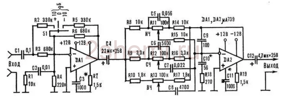
The input stage on DA1 contains a gain level switch (-10; 0; +10 dB), which simplifies the matching of the entire amplifier with signal sources of different levels, and the tone control is directly assembled on DA2. The circuit is not capricious to some variation in the values of the elements and does not require any adjustment. As an op-amp, you can use any microcircuits used in the audio paths of amplifiers, for example, here (and in subsequent circuits) I tried the imported BA4558, TL072 and LM2904. Any will do, but it is better, of course, to choose op-amp options with the lowest possible noise level and high performance (input voltage slew factor). These parameters can be viewed in reference books (datasheets). Of course, it is not at all necessary to use this particular scheme here; it is quite possible, for example, to make not a three-band, but a regular (standard) two-band tone block. But not a “passive” circuit, but with amplification-matching stages at the input and output on transistors or an op-amp.
Filter block
If you wish, you can also find a lot of filter circuits, since there are now enough publications on the topic of multi-band amplifiers. To make this task easier and just as an example, I will list here a few possible schemes found in various sources:
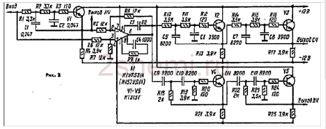
- the circuit that I used in this amplifier, since the crossover frequencies turned out to be exactly what the “customer” needed - 500 Hz and 5 kHz and I didn’t have to recalculate anything.
- the second circuit, simpler on an op-amp.
And another possible circuit, using transistors:
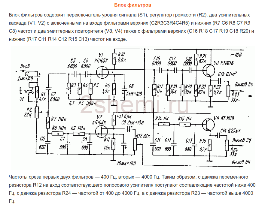
As yours already wrote, I chose the first scheme because of the fairly high-quality filtering of the bands and the correspondence of the band separation frequencies to the specified ones. Only at the outputs of each channel (band) simple gain level controls were added (as was done, for example, in the third circuit, using transistors). Regulators can be supplied from 30 to 100 kOhm. Operational amplifiers and transistors in all circuits can be replaced with modern imported ones (taking into account the pinout!) to obtain better circuit parameters. All these circuits do not require any adjustment unless you need to change the crossover frequencies. Unfortunately, I am not able to provide information on the recalculation of these crossover frequencies, since the circuits were looked for as “ready-made” examples and no detailed descriptions were attached to them.
The ability to disable filtering on the MF and HF channels has been added to the filter block circuit (the first of three circuits). For this purpose, two push-button switches of the P2K type were installed, with the help of which you can simply close the connection points of the filter inputs - R10C9 with their corresponding outputs - “HF output” and “MF output”. In this case, the full audio signal is transmitted through these channels.
Power amplifiers
From the output of each filter channel, HF-MF-LF signals are fed to the inputs of power amplifiers, which can also be assembled using any of the known circuits, depending on the required power of the entire amplifier. I made the UMZCH according to the long-known scheme from the magazine “Radio”, No. 3, 1991, p. 51. Here I provide a link to the “original source”, since there are many opinions and disputes regarding this scheme regarding its “quality”. The fact is that at first glance this is a class “B” amplifier circuit with the inevitable presence of “step” distortion, but this is not so. The circuit uses current control of the transistors of the output stage, which allows you to get rid of these shortcomings during normal, standard switching on. At the same time, the circuit is very simple, is not critical to the parts used, and even the transistors do not require special preliminary selection of parameters. In addition, the circuit is convenient in that powerful output transistors can be placed on one heat sink in pairs without insulating spacers, since the collector terminals are connected at the point " output”, which greatly simplifies the installation of the amplifier:

When setting up, it is only IMPORTANT to select the correct operating modes of the transistors of the pre-final stage (by selecting resistors R7R8) - at the bases of these transistors in the “rest” mode and without load at the output (dynamics) there should be a voltage in the range of 0.4-0.6 volts. The supply voltage for such amplifiers (there should be 6 of them, accordingly) was raised to 32 volts with the replacement of the output transistors with 2SA1943 and 2SC5200, the resistance of resistors R10R12 should also be increased to 1.5 kOhm (to “make life easier” for the zener diodes in the circuit power supply of input op-amps). The op-amps were also replaced with BA4558, in which case the “zero setting” circuit (outputs 2 and 6 in the diagram) is no longer needed and, accordingly, the pinout changes when soldering the microcircuit. As a result, when tested, each amplifier using this circuit produced power up to 150 watts (short-term) with a completely adequate degree of heating of the radiator.
ULF power supply
Two transformers with blocks of rectifiers and filters were used as a power supply according to the usual, standard scheme. To power the low-frequency band channels (left and right channels) - a 250-watt transformer, a rectifier based on diode assemblies such as MBR2560 or similar, and 40,000 uF x 50 volt capacitors in each power arm. For the midrange and high-frequency channels - a 350-watt transformer (taken from a burnt-out Yamaha receiver), a rectifier - a TS6P06G diode assembly and a filter - two capacitors of 25,000 uF x 63 volts for each power arm. All electrolytic filter capacitors are shunted by film capacitors with a capacity of 1 microfarad x 63 volts.
In general, the power supply can have one transformer, of course, but with its corresponding power. The power of the amplifier as a whole in this case is determined solely by the capabilities of the power source. All preamplifiers (timbre block, filters) are also powered from one of these transformers (possibly from any of them), but through an additional bipolar stabilizer unit assembled on a KREN (or imported) MS or using any of the standard transistor circuits.
Homemade amplifier design
This was, perhaps, the most difficult moment in manufacturing, since there was no suitable ready-made housing and I had to come up with possible options :-)) In order not to sculpt a bunch of separate radiators, I decided to use a radiator housing from a car 4-channel amplifier, quite large in size, something like this:

All the “internals” were, naturally, removed and the layout turned out something like this (unfortunately, I didn’t take a corresponding photo):

— as you can see, six terminal UMZCH boards and a pre-amplifier-timbre block board were installed in this radiator cover. The filter block board no longer fit, so it was secured to a structure made from an aluminum corner that was then added (it can be seen in the pictures). Also, transformers, rectifiers and power supply filters were installed in this “frame”.
The view (from the front) with all the switches and controls turned out like this:

Rear view, with speaker output terminals and fuse box (since no electronic protection circuits were made due to lack of space in the design and in order not to complicate the circuit):

Subsequently, the frame from the corner is, of course, supposed to be covered with decorative panels to give the product a more “marketable” appearance, but this will be done by the “customer” himself, according to his personal taste. But in general, in terms of sound quality and power, the design turned out to be quite decent. Author of the material: Andrey Baryshev (especially for the site website).