Motherboard repair: swollen capacitors. Replacing capacitors on the motherboard
The motherboard is a very complex electronic device that combines and coordinates the operation of all computer components. Over time, the motherboard may fail for various reasons: overheating, aging components, etc.
Very often on old motherboards you can find swollen electrolytic capacitors. They look like barrels with a swollen top or bottom. In this case, there may be traces of leaked electrolyte near the capacitor. Such motherboard, in principle, can work successfully, but most often a computer with such motherboard won't start.
To bring the motherboard back to (feelings), you should replace the swollen capacitors with new ones. You can do this type of repair yourself without help. service center. However, if you have never held a soldering iron in your hands and do not have the slightest idea how to work with it, then it is better to contact them in order to avoid aggravating the situation and completely (killing) the system motherboard.

To replace capacitors, you will need a low-power soldering iron (up to 40W) with a narrow tip or a soldering station (ideally), rosin or soldering acid (preferred), tin solder, alcohol or purified gasoline.

Before you begin to solder the capacitor, carefully inspect the motherboard, find any capacitors that are swollen or have traces of leaked electrolyte. Electrolytic capacitors are soldered with respect to polarity. Their housing is usually marked with a negative (-) terminal designation. On the most motherboard, when you solder the capacitor, there is also a polarity marking. In order not to confuse the polarity, you can photograph the location of the capacitors.

And a few more words about preparatory work. The motherboard is sensitive to static voltage, so it would be advisable to ground the soldering iron and the motherboard. For the same reason, you cannot work in synthetic clothing without observing additional measures protection. Use antistatic gloves and wrist straps.
Desoldering the capacitor requires special care, since the printed circuit board has a multi-layer assembly. This means that the tracks not only go on both sides of the board, but also inside it! If you use a soldering iron, heat the legs of the capacitor one at a time and carefully remove it from the printed circuit board. After this, the holes in the board should be cleaned of any remaining solder. You can use a toothpick, which should be inserted into each hole one by one and heat the board on the other side with a soldering iron. This way, any remaining tin will be removed. If you use a soldering iron with tin suction, then cleaning the board from solder residues will not be necessary.

When the capacitors are soldered, you need to check their rating and operating voltage in order to purchase new ones to replace them. The capacitance of the capacitor is indicated in microfarads (µF, uF), and the voltage in volts (V, V). If a soldered capacitor, for example, is marked 6.3V 2000uF, then its operating voltage is 6.3 V and the capacitance is 2000uF. When purchasing a new capacitor, you may not find exactly the same capacity and operating voltage. It is allowed to install capacitors with a higher operating voltage (12V instead of 6.3V) and a larger capacity (2200 µF instead of 2000 µF). It is highly not recommended to use capacitors with lower voltages, since such a capacitor will fail very quickly.
Also, when choosing a capacitor, you should Special attention Pay attention to its size, since the motherboard has a tight installation, and the components are often installed almost end-to-end, then installing a larger diameter capacitor may not be possible. With capacitors that are large in height, there are usually no installation problems.
Now all that remains is to carefully solder the new capacitor and check the functionality of the motherboard. Install the capacitor into the motherboard, being sure to observe the polarity, and solder its legs with reverse side printed circuit board. Do not use a large number of solder so that it does not spread and short-circuit adjacent contacts. When soldering, avoid excessive heating of the board, as this can lead to desoldering of adjacent elements. Once everything is soldered, remove any remaining soldering acid or rosin from the PCB using alcohol or refined gasoline.
Dear guests, in this article we will make a replacement swollen capacitors on the motherboard with your own hands. I would like to say right away that replacing capacitors with your own hands requires knowledge and skills in using such a tool as a soldering iron. IN in this case I used a simple Soviet soldering iron. If you do not have such experience, then I do not recommend taking on such work. We read about replacing capacitors on the power supply.
Typically, capacitors on the motherboard begin to fail after 3-4 years of using the computer. This is usually a normal phenomenon, and all this can be solved by replacing them with new ones.
How to determine that the capacitors on the motherboard are swollen, what are the signs? Now let's look at everything in more detail.
Signs of faulty capacitors on the motherboard
1. When you turn on the computer, it turns on, then turns off. After turning it on 3-4 times it turns on normally and boots operating system. After that, it works without problems, but as soon as you turn it off and on the next day, the problem repeats itself. These signs indicate that the capacitors on the board may have dried out and swelled.
2. The computer simply does not turn on. This could also be due to capacitors or a problem with the power supply. How to check the power supply, read.
3. When you turn on or operate your computer, a blue screen often appears. This can also cause swelling and malfunctioning capacitors on the motherboard. As a rule, these are the primary signs when the capacitors just begin to swell.
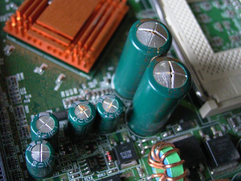
4. Open the side cover of the system unit and carefully inspect the motherboard. As a rule, you can visually determine that the capacitors on the motherboard are swollen and require replacement. Example in the picture.
The picture shows in an approximate way that 2 capacitors on the motherboard are swollen and require replacement. It is necessary to inspect the motherboard carefully, because... An inexperienced person in this matter may not always be able to identify a faulty capacitor the first time. After this, we need to find new replacement capacitors. Usually you can take them from an old motherboard or buy them from radio parts; they are not expensive. Solder off the old capacitors, look at the rating and buy new ones, you can take the old ones with you to show the seller (you can take more by voltage, but not less). In my example this 6.3 volts 1500 uF. Instead I used 16 volts 1500 uF.

If you or your friends have an old motherboard, you can desolder them from it. That's it, we have everything ready, after that we begin replacing the capacitors on the motherboard with our own hands. As I already wrote above, replacing capacitors on the motherboard with your own hands requires certain skills in working with a soldering iron, if you are ready, let's get started.
When replacing capacitors we will need the following tool:
- Soldering iron;
- Rosin;
- Solder;
- Toothpicks;
- Purified gasoline (to remove rosin from the board).

Ideally, to desolder such parts you need to use a desoldering pump or a soldering hair dryer. Since I only have a soldering iron at home, I had to desolder it, alternately heating the legs of the capacitor and pulling it out. Conclusion: doing this with a simple soldering iron is extremely inconvenient.
After we have removed the old capacitor and prepared a replacement for it, we need to clean the holes for the capacitor, otherwise the old solder will not allow it to be inserted properly. The desalination pump could have been done in a couple of seconds, but I had to fiddle around and use toothpicks. Carefully insert them into the holes and heat them with a soldering iron from the back to push out all the excess solder. I repeat once again that this must be done carefully, since the board is multi-layered and the tracks inside the board can be damaged 
After cleaning the holes, insert the capacitor into place, be sure to observe polarity. Usually, on the motherboard there are markings for installing capacitors (the shaded side is the minus “ - "), but it's best to remember how the old one was installed. On the capacitors themselves there are also symbols in the form of a strip with the sign " - «.
We seal it on the reverse side. I don’t have a photo of the process itself, since I couldn’t solder and take pictures at the same time. But there is a photo of the final result)

Don't forget to clean the board from flux or rosin.
Well, that's it, my repair is over. The main thing is not to be afraid and carefully try to solder with your own hands. I must say, this is a very exciting process.
Just in case, I’m giving you a video where you can also watch how the process of replacing capacitors on the motherboard with your own hands occurs.
The most common breakdown modern electronics- this is a malfunction of electrolytic capacitors. If you, after disassembling the case electronic device If you noticed that there are capacitors on the printed circuit board with a deformed, swollen body, from which toxic electrolyte is oozing, then it’s time to figure out how to recognize a breakdown or defect in the capacitor and select an adequate replacement. Having a professional soldering flux, solder, a soldering station, and a set of new capacitors, you can easily “revive” any electronic device with your own hands.
In essence, a capacitor is a radio-electronic component, the main purpose of which is the accumulation and release of electricity for the purpose of filtering, smoothing and generating alternating electrical oscillations. Any capacitor has two important electrical parameter: capacity and maximum constant pressure, which can be applied to a capacitor without breakdown or destruction. Capacity usually determines how much electrical energy can absorb a capacitor if a constant voltage is applied to its plates, not exceeding a given limit. Capacitance is measured in Farads. The most widely used capacitors are those whose capacitance is calculated in microfarads (μF), picofarads (pF) and nanofarads (nF). In many cases, it is recommended to replace a faulty capacitor with a serviceable one that has similar capacitance characteristics. However, in repair practice there is an opinion that in power supply circuits it is possible to install a capacitor with a capacity slightly higher than the factory parameters. For example, if we want to replace a ruptured electrolyte with 100 µF 12 Volt in the power supply, which is designed to smooth out fluctuations after the diode rectifier bridge, we can safely set the capacitance even to 470 µF 25 V. Firstly, increased capacity a capacitor will only reduce ripple, which in itself is not bad for a power supply. Secondly, an increased voltage limit will only increase the overall reliability of the circuit. The main thing is that the space allocated for installing the capacitor is suitable.
Why do electrolytic capacitors explode?
The most common reason why an electrolytic capacitor explodes is excess voltage between the capacitor plates. It's no secret that in many devices made in China The maximum voltage parameter exactly matches the applied voltage. According to their idea, capacitor manufacturers did not foresee that in the normal inclusion of a capacitor in the electrical circuit, exactly maximum voltage. For example, if the capacitor says 16V 100uF, then you should not connect it to a circuit where 15 or 16V will be constantly supplied to it. Of course, he will withstand such abuse for some time, but the safety margin will be practically zero. It is much better to install such capacitors in a circuit with a voltage of 10–12V, so that there is some voltage reserve.
Polarity of connection of electrolytic capacitors
Electrolytic capacitors have negative and positive electrodes. As a rule, the negative electrode is identified by the markings on the body (a white longitudinal strip behind the “-” signs), and the positive plate is not marked in any way. The exception is domestic capacitors, where, on the contrary, the positive terminal is marked with a “+” sign. When replacing capacitors, it is necessary to compare and check whether the polarity of the capacitor connection corresponds to the markings on the printed circuit board (the circle where there is a shaded segment). By matching the negative strip with the shaded segment, you will correctly insert the capacitor. All that remains is to cut off the legs of the capacitor, process the soldering points and solder them properly. If you accidentally reverse the polarity of the connection, then even a completely new and completely serviceable capacitor will simply rupture, simultaneously smearing all adjacent components and printed circuit board conductive electrolyte.
A little about security
It is no secret that replacing low-voltage capacitors can only be harmful to health if the polarity connection is incorrect. The first time you turn it on, the capacitor will explode. The second danger that can be expected from capacitors is the voltage between its plates. If you've ever taken apart computer power supplies, you've probably noticed the huge 200V electrolytes. It is in these capacitors that dangerous high voltages remain that can seriously injure you. Before replacing the capacitors of the power supply, we recommend completely discharging it either with a resistor or a 220V neon lamp.
Helpful advice: such capacitors really don’t like to be discharged through short circuit, so do not short-circuit their terminals with a screwdriver for the purpose of discharge.
If your computer freezes, works with errors, Windows does not install. If the computer does not start at all, or once it starts, it immediately stops, do not be lazy to open the lid system unit and the problem can be seen with the naked eye - this electrolytic capacitors on the motherboard. One of the most common causes of motherboard failure is breakdown, short-circuiting or leakage of electrolytic capacitors. The filter capacitors in the processor voltage regulator or north bridge usually fail.
 Typically, faulty capacitors can be detected by a swollen rear part of the case or leaked electrolyte, but not necessarily. It happens that the capacitor is absolutely normal in appearance, but it is also not working properly. Rough check of the electrolytic capacitor without external damage, can be done using a dial ohmmeter by throwing the arrow. To check the capacitor, the ohmmeter is placed at the lowest range of resistance measurement and connected to the terminals of the capacitor; in the initial period, the capacitor will begin to charge and the instrument needle will deflect, and then as it charges, it will return to its place. You can repeat the test by changing the terminals of the capacitor. The more and slower the needle deviates, the greater the capacitance of the capacitor. If the ohmmeter shows zero, then the capacitor is shorted, and if it is infinity, then a break is likely. If, as the arrow returns to initial position it stops at some position without returning to its original position, then the capacitor is also faulty.
 To approximately determine the capacitance of a capacitor, you can compare the behavior of the instrument needle when connecting a known-good capacitor of the same capacity and the one being tested. To avoid damaging the device, it is necessary to discharge the capacitor by short-circuiting its terminals. Sometimes the condition of the capacitor can be determined with an ohmmeter without unsoldering it, if it is not bypassed by other elements of the circuit, but for a quality check it is still better to unsolder it. You can desolder and solder capacitors with any soldering iron of not very high power (up to 65 watts) using rosin or other soldering flux. After desoldering the capacitors, you need to clear the solder from the holes. I do this using a regular sewing needle, applying the tip of the needle to the hole on the side where the capacitor housings are located and at the same time the tip of the soldering iron on the other side.
The capacitance of the capacitors does not have to be selected exactly; it is possible with a deviation in any direction of up to 30% or even more. If the capacity of the existing capacitors is significantly smaller, then you can add another one; in processor stabilizer filters they are connected in parallel and there are free ones, reserve places. In no case should the voltage rating of the capacitors be chosen less than before. You should pay attention to the temperature rating, it should be 105 0 C. Polarity must be observed. If, having soldered the capacitors, you do not remember how they were positioned, then look carefully at how the others are located and solder them in the same way. When selecting capacitors to replace those located near the processor, it is necessary to take into account the cooler radiator so that they do not interfere with installing it in place. If you do not have the opportunity or desire to replace capacitors, then contact specialists who can do it efficiently and without problems. Typically, the cost of such repairs does not exceed 50% of the cost of the motherboard. Although, most likely no one will give you a guarantee in this case. It's up to you to decide whether to repair or replace?
One of the most common reasons motherboard problems - failed capacitors. Today we will tell you how to replace them correctly.
The first thing to note is that the procedure for replacing capacitors is a very delicate, almost surgical procedure, which will require appropriate skill and experience. If you are not confident in your abilities, then it is better to entrust the replacement to a specialist.
If you have the necessary experience, make sure that in addition to it you have the appropriate equipment.
Replacement capacitors
The most important element. These components differ from each other in two ways key parameters: voltage and capacitance. Voltage represents the operating voltage of the element, capacitance represents the amount of charge that the capacitor can hold. Therefore, when choosing new components, make sure that their voltage is equal to or slightly higher than the old ones (but in no case less!), and that the capacity exactly matches the failed ones.
Soldering iron
This procedure requires a soldering iron with a power of up to 40 W with a thin tip. You can use a soldering station with power adjustment. In addition, be sure to purchase a suitable flux for your soldering iron.
Steel needle or piece of wire
A sewing needle or a piece of thin steel wire will be needed to clean and widen the hole in the board for the legs of the capacitors. It is not advisable to use thin objects made of other metals, as they may be seized by the solder, which will create additional difficulties.
Once you are sure that the inventory meets the requirements, you can proceed directly to the replacement procedure.
Replacing faulty capacitors
Warning! Further actions you do it at your own peril and risk! We do not bear any responsibility for possible damage to the board!
This procedure takes place in three stages: desoldering old capacitors, preparing the site, installing new elements. Let's look at each in order.
Stage 1: Desoldering
To avoid failures, it is recommended before starting manipulations. The procedure goes like this.

If there are several capacitors, repeat the above procedure for each. Having pulled them out, proceed to the next step.
Stage 2: Preparing the seat
This is the most an important part procedures: whether you can install a new capacitor depends on competent actions, so be extremely careful. In most cases, when removing elements, solder gets into the leg hole and clogs it. To clear the area, use a needle or piece of wire as follows.


After making sure that the board is prepared, you can move on to the last stage.
Stage 3: Installation of new capacitors
As practice shows, most mistakes are made at this step. Therefore, if the previous stages have tired you, we recommend taking a break and only then proceeding to the final part of the procedure.

After completing the procedure, let the solder cool and check the results of your work. If you followed the above instructions exactly, there shouldn't be any problems.
Alternative replacement option
In some cases, in order to avoid unnecessary heating of the board, you can do without soldering the faulty capacitor. This method is rougher, but is suitable for users who are not confident in their abilities.

That's all. Finally, we would like to remind you once again - if you think that you cannot cope with the procedure, it is better to entrust it to the master!