Connecting wires to the connector. How to extend and connect an Internet cable at home
Despite the advances by leaps and bounds wireless technologies, in an apartment building or private household desktop computers, TV set-top boxes, file storages are best connected using a cable or twisted pair. To do this, it is important not only to correctly route the wire around the room, but also to crimp the RJ-45 standard connectors at the ends of the cable.
Types of cables for Internet connection
Depending on the type of provider, the cable can be routed to the subscriber in several ways. If the connection is made using the Wi-MAX, LTE or 3G standard, there may not be a cable at all.
Telephone cable
Used when connecting to the Internet using aDSL technology. The wire is used in two- and four-core wires; when using four wires, you can increase the length of the cable route and reduce interference. In some cases, the same line is also connected landline phone. Used for connection special cable digital modem or modem router.
Often for last mile telephone line single-core copper “noodles” are used, the speed and quality of such an Internet channel will be low
Providers use this type of cable to connect network subscribers cable television. Thanks to the wide bandwidth coaxial cable transmits both data and analog TV signals without mutual interference. As with a telephone line, a special modem is used for connection.
Coaxial cable is used when laying dual-use networks, for example, Internet + analog TV
Fiber optic
Fiber optic cable is used to connect either multi-storey buildings, with the installation of subscriber routers in the entrances, or houses in the private sector, since this type of cable transmits the signal over vast distances without reducing the signal level or interference. A converter, or interface converter, allows you to connect a router-router to such a cable using a patch cord made of ordinary twisted pair (UTP).
Fiber optic cable is used for laying long and interference-free routes
Twisted pair (UTP)
This is the most common and inexpensive type of connection. These cables bring the Internet to an apartment or house, and also connect client devices (computers, TV set-top boxes, printers) to the router. Cables come in four and eight cores. Four cores transmit data at speeds of up to 100 Mbit/s, and the eight-core version allows you to increase the speed tenfold.
UTP-8 is the most common wire for laying a local network
Without additional amplifying equipment, the length of cable routes will be small (up to 100 meters). Nevertheless, twisted pair connection is a popular type of connection due to the low cost of the wire and connectors, as well as the ability to cut the cable with or without a cheap tool. Whatever wire enters the house, all the same, after the interface converter or cable modem, the good old twisted pair.
Types of twisted pair
The wire for creating patch cord cables and cable routes differs both in the insulation material and in the composition of the central core (conductor). The cheap one is made of aluminum conductors and plastic insulation, designed for indoor use. Electrical resistance aluminum is higher than copper, and the signal in such a wire attenuates faster. Accordingly, it is worth making only short cables for indoor use, for example, connecting computers in an apartment or small private house to the router.
Use cheap UTP cable only indoors and when creating short network segments
The expensive wire is supplemented with another layer of insulation and a thick steel core, which takes on mechanical loads when suspended. Protected frost-resistant wire with copper conductors costs 3–4 times more, but with its help you can lay long sections of cable routes inside entrances and even between individual houses. It is worth noting that in Lately Such routes are increasingly being made using fiber optic cable.
Protected twisted pair cable is equipped with additional insulation and steel wire for suspension
Tools required for crimping twisted pair cables
You will need crimping pliers (for 99% of the job), a utility knife or a strong utility knife, and a small flashlight.
Crimping pliers, or crimper, are the cableman’s main tool.
From Supplies You will need UTP wire and RJ-45 connectors. If the connectors do not come with silicone caps, a hot glue gun will be useful.
Using RJ45 connectors with silicone caps will not only protect the cable from damage, but also make the connection clearer
If there are no mounting pliers, a small hammer and a flat-head screwdriver with a blade width equal to the width of the contact group of the RJ-45 connector will serve as a substitute.
A cable tester - a device for checking crimped cables - will be extremely useful. If there is a break in the cable or there is no contact in one or two wires, the connection will become unstable.
The cable tester is indispensable for large volumes of cable work and long routes.
Twisted pair crimping circuits
Regardless of the number of cores, cables are divided into two types: straight and crossed. Crossovers are used to connect two computers into a peer-to-peer local network, without a router. If you use a router to build a network, then use any type of cable, since the router automatically detects which cable is connected.
Crimping 4-core cable
A four-core cable can be used indoors at network speeds up to 100 Mbit/s. If you examine the connectors of an inexpensive 100-Mbit router, you will find that each socket is equipped with only four contacts and using an 8-core cable will not provide any advantages. You can perform straight or cross crimping.
Direct crimping of four-core patch cord
The difference between the two types of crimping is the location of the orange and green cores.
Cross crimping of four-core patch cord
Crimping 8-core cable
There are more options for pressing in an 8-core cable, which is not surprising, because local networks with such a cable are the most common. Direct cable pressing can be done in two ways; they differ in the location of the orange cores. Type T586B is a de facto standard in the Russian Federation, and type T586A is common in the European Union and the USA.
Type T586V - the main one for crimping direct patch cords in the Russian Federation
The standards differ in the location of the green and orange cores. Core colors may vary depending on the cable manufacturer.
Type of crimping T586 is practiced in the USA and EU countries
Cable cross-crimping also has two options: for low-speed networks (10–100 Mbps) and for modern gigabit LANs.
Simple crimping is suitable for low speed networks
The difference between simple and cross crimping is the location of the blue and brown wires.
Use cross-pressure for high speed networks
How to crimp a patch cord cable using pliers
Prepare your tools: pliers, a flashlight and a knife.
- Using the miter knife of the pliers, straighten the end of the cable. If the cable was cut in a store with a regular knife, the end is probably beveled.
- Remove the insulation from the network cable. To do this, place the cable in the recess of the stripping tool so as to remove the insulation by 2–2.5 cm. Rotating the cable relative to the knife, cut it along the entire circumference. Remove the cut piece of insulation to expose the colored strands.
Remove the cable insulation using a special tool
- Unbraid the veins. The length of the unbraided section should not be more than 12–13 mm. If it is difficult to align the strands, you can unbraid them to a greater length, and then trim the unbraided and aligned end.
The wire strands are unraveled to a length of 12–13 mm
- Align and arrange the braided strands in the color scheme that matches the cable type.
Align the cable cores according to the color scheme
- Taking the new RJ-45 connector, unfold it with the plastic lock facing down and carefully push the end of the cable into it along the guides. The vinyl chloride insulation tube must reach the inner locking tooth in the connector. If the wire is not inserted completely, the wires may come off.
Carefully insert the unraveled end of the cable into the connector
- Check that the wires in the connector are in order and not damaged. If everything is fine, insert the connector into the connector of the crimping pliers and squeeze them all the way, but not too much.
Crimp the RJ-45 connector with a crimper
- After crimping, the cable is ready for use.
Video: crimping a twisted pair cable
Crimping patch cord without pliers
If you rarely crimp cables or decide to help a friend, but the pliers are left at home, crimping can be done with improvised means that everyone has in their pantry. You will need a flathead screwdriver, a utility knife with a new blade, and a hot glue gun.
- Align the end of the cable with the blade of a sharp knife. Then, stepping back 2–2.5 cm from the end, make a neat circular cut on the insulation. Try not to cut through it so as not to damage the colored wires. After turning the cut section of insulation back and forth several times, separate it.
Strip the cable insulation using a regular knife
- Unbraid the wires so that the length of the unbraided section does not exceed 12–13 mm. If you have difficulty aligning the strands, unbraid them to a greater length, and then trim the unbraided and aligned end.
You can trim the wires to the desired length with wire cutters or a regular knife.
- Align the braided wires and arrange them in a color scheme that matches the type of cable being crimped.
- Now take the new RJ-45 connector and unfold it with the plastic lock facing down. Then carefully push the end of the cable into it along the guides. The insulating vinyl chloride tube must reach the inner lock tooth in the connector. If the wire is not completed to the end, the cores may come off during operation of the cable. Inspect the connector: the wires must be positioned correctly.
Check that the wires are positioned correctly. If you make a mistake, you will have to cut off the connector and crimp on a new one.
- Using a screwdriver, push each of the eight pins down so that they cut into the corresponding colored wire. Place a screwdriver on the contact and press it down. There are only a couple of free millimeters in the connector for maneuver; if you overdo it, you can easily damage it. Repeat this action seven more times.
Press the connector pins down until they penetrate the cable cores
- Using a heat gun, fill the inside of the connector with glue to secure the cable insulation in it.
- Check the quality of the crimp by connecting the cable to an RJ-45 socket (router or laptop). If the connector does not snap fully into place, remove it and repeat steps from step 5.
- When the cable has passed the test, it is ready for use.
Video: crimping connectors using a screwdriver
There is nothing complicated about crimping a twisted pair cable. Half an hour with a special tool or a little longer with improvised means - and your home local network is already working, and cable connection pleases with maximum speed and lack of delays. Remember that a device with a cable Internet connection works faster than over the air and also reduces exposure to high-frequency radiation.
Almost no local network can do without wired segments, where computers are connected to the network using cables. In this material you will learn what types and types of cables are used to create local networks, and you will also learn how to make them yourself.
Almost no local network, be it home or office, can do without wired segments where computers are connected to the network using cables. This is not surprising, because this solution for transferring data between computers is still one of the fastest and most reliable.
Types of network cable
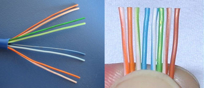
In wired local networks, a special cable called “twisted pair” is used to transmit signals. It is called that because it consists of four pairs of copper strands twisted together, which reduces interference from various sources.
.jpg)
In addition, the twisted pair has a common external dense insulation made of polyvinyl chloride, which is also very little susceptible to electromagnetic interference. Moreover, on sale you can find both an unshielded version of the UTP (Unshielded Twisted Pair) cable and shielded varieties that have additional screen from foil - either common for all pairs (FTP - Foiled Twisted Pair), or for each pair separately (STP - Shielded Twisted Pair).
Using a modified twisted pair cable with a screen (FTP or STP) at home only makes sense when there is high interference or to achieve maximum speeds with a very long cable length, which should preferably not exceed 100 m. In other cases, a cheaper unshielded UTP cable, which can be found, will do at any computer store.
Twisted pair cable is divided into several categories, which are marked from CAT1 to CAT7. But you shouldn’t be immediately afraid of such diversity, since for building home and office computer networks Mostly unshielded cable CAT5 or its slightly improved version CAT5e is used. In some cases, for example, when the network is laid in rooms with large electromagnetic interference, you can use a sixth category cable (CAT6), which has a common foil screen. All of the categories described above are capable of providing data transmission at speeds of 100 Mbit/s when using two pairs of cores, and 1000 Mbit/s when using all four pairs.
Crimping schemes and types of network cable (twisted pair)
Twisted pair crimping is a crimping procedure. special connectors at the ends of the cable, which use 8-pin 8P8C connectors, which are usually called RJ-45 (although this is somewhat misleading). In this case, the connectors can be either unshielded for UTP cables or shielded for FTP or STP cables.

Avoid purchasing so-called plug-in connectors. They are designed for use with soft stranded cables and require some skill to install.
To lay the wires, 8 small grooves are cut inside the connector (one for each core), above which metal contacts are located at the end. If you hold the connector with the contacts up, the latch facing you, and the cable input is facing you, then the first contact will be located on the right, and the eighth on the left. Pin numbering is important in the crimping procedure, so remember this.
There are two main schemes for distributing wires inside connectors: EIA/TIA-568A and EIA/TIA-568B.

When using the EIA/TIA-568A circuit, wires from pins one to eight are laid out in the following order: White-Green, Green, White-Orange, Blue, White-Blue, Orange, White-Brown, and Brown. In the EIA/TIA-568B circuit, the wires go like this: White-Orange, Orange, White-Green, Blue, White-Blue, Green, White-Brown and Brown.
For the manufacture of network cables used for interconnection computer devices and network equipment in various combinations, there are two main cable crimping options: straight and crossover (crossover). Using the first, most common option, cables are made that are used to connect the network interface of a computer and other client devices to switches or routers, as well as connect modern network equipment to each other. The second, less common option is used to make a crossover cable, which allows you to directly connect two computers through network cards, without the use of switching equipment. You may also need a crossover cable to connect old switches into a network via up-link ports.
What to make straight network cable , it is necessary to crimp both ends the same scheme. In this case, you can use either option 568A or 568B (used much more often).

It is worth noting that to make a straight network cable it is not at all necessary to use all four pairs - two will be enough. In this case, using one twisted pair cable, you can connect two computers to the network at once. Thus, if high local traffic is not planned, the wire consumption for building a network can be halved. However, keep in mind that at the same time, maximum speed Data exchange on such a cable will drop 10 times - from 1 Gbit/s to 100 Mbit/s.

As can be seen from the figure, in in this example Orange and Green pairs are used. To crimp the second connector, the place of the Orange pair is taken by Brown, and the place of Green by Blue. In this case, the connection diagram to the contacts is preserved.
For the manufacture of crossover cable necessary one crimp its end according to circuit 568A, and second- according to the 568V scheme.

Unlike a straight cable, all 8 cores must always be used to make a crossover. At the same time, a crossover cable for data exchange between computers at speeds of up to 1000 Mbit/s is manufactured in a special way.

One end of it is crimped according to the EIA/TIA-568B scheme, and the other has the following sequence: White-green, Green, White-orange, White-brown, Brown, Orange, Blue, White-blue. Thus, we see that in circuit 568A the Blue and Brown pairs have swapped places while maintaining the sequence.
Finishing the conversation about circuits, we summarize: by crimping both ends of the cable according to the 568V circuit (2 or 4 pairs), we get straight cable to connect a computer to a switch or router. By crimping one end according to circuit 568A and the other according to circuit 568B, we get crossover cable for connecting two computers without switching equipment. A special feature is the production of gigabit crossover cable, where a special circuit is required.
Crimping a network cable (twisted pair)
For the cable crimping procedure itself, we will need a special crimping tool called a crimper. Crimper is a pliers with several working areas.

In most cases, knives for cutting twisted pair wires are placed closer to the tool handles. Here, in some modifications, you can find a special recess for stripping the outer insulation of the cable. Further, in the center of the working area, there are one or two sockets for crimping network (marking 8P) and telephone (marking 6P) cables.
Before crimping the connectors, cut a piece of cable to the required length at a right angle. Then, on each side, remove the common outer insulating sheath by 25-30 mm. At the same time, do not damage the own insulation of the conductors located inside the twisted pair.
Next, we begin the process of sorting the cores by color, according to the selected crimping pattern. To do this, unravel and straighten the wires, then arrange them in a row in in the right order, pressing tightly together, and then trim the ends with a crimper knife, leaving approximately 12-13 mm from the edge of the insulation.
Now we carefully place the connector on the cable, making sure that the wires do not get mixed up and that each of them fits into its own channel. Push the wires all the way until they rest against the front wall of the connector. With the correct length of the ends of the conductors, they should all fit into the connector all the way, and the insulating sheath must be inside the housing. If this is not the case, then remove the wires and shorten them somewhat.

After you have placed the connector on the cable, all that remains is to fix it there. To do this, insert the connector into the corresponding socket located on the crimping tool and smoothly squeeze the handles until they stop.
Of course, it’s good when you have a crimper at home, but what if you don’t have one, but you really need to crimp the cable? It is clear that you can remove the outer insulation with a knife, and use ordinary wire cutters to trim the cores, but what about the crimping itself? In exceptional cases, you can use a narrow screwdriver or the same knife for this.

Place a screwdriver on top of the contact and press it so that the teeth of the contact cut into the conductor. It is clear that this procedure must be done with all eight contacts. Finally, push the central cross section to secure it in the cable insulation connector.
And finally, I’ll give you a little advice: Before crimping the cable and connectors for the first time, buy with a reserve, since not everyone can perform this procedure well the first time.
The Internet has very quickly and extremely firmly entered into life. modern man. It is now difficult to even imagine housing that is not equipped with a connection line worldwide network, wired or optical. However, as a rule, the provider’s area of responsibility ends with the modem or router. That is, if the owners’ plans are not limited to installing one computer, but involve creating an entire home local network, including connecting IP television, then you will either have to deal with these issues yourself, or invite specialists for a separate fee.
When improving home network Almost never goes without laying LAN cables. Purchasing a twisted-pair cable itself is not a problem - it comes in a wide variety, and its price is quite affordable. But turning it into a patch cord or a full-fledged line means mounting (more often they say, crimping) special contact tips and connectors at the ends. This is, in principle, the whole difficulty. But the complexity is not so great that it is mandatory to give money to the invited master for this. That is, this operation can be carried out on your own. And even using the simplest tools.
So, let's learn how to crimp an Internet cable yourself. Sooner or later such a skill will be in demand.
There are many cases when it is necessary to resort to the use of such a compound. And with the increasing saturation of family life, modern technology is becoming more and more common.

- The number of computers in the house has increased. A Wi-Fi connection is certainly convenient, but it has its vulnerabilities and disadvantages. It is more reliable and better to carry out switching using a LAN cable.
- More and more people are switching to IP-TV (SMART-TV). And again, to ensure a guaranteed stable signal supply, you can’t think of anything better than twisted pair.
- Network connections are sometimes required by other modern Appliances, equipped with remote control functions.
- Even in one room there may be several devices that require such a connection. This means that a router or switch is installed, to which connecting patch cords are connected in the required quantity.
- Even a high-quality LAN cable can fail due to accidental damage or simple wear of the connector contact group. Another common reason is a broken lock on the connector body. It’s a small thing, but because of it the connector is poorly held in the router socket, network card and so on. This means it is better to replace it with a new one.
There may be other situations - you can’t foresee everything. In any case, the ability to crimp a network cable will definitely come in handy.
And in order to do everything correctly, with an understanding of the issue, you must first understand at least a little about the structure of the LAN cable.
First of all, about the cable itself. It is called twisted pair for a reason. Under the outer insulating sheath there are actually several pairs of spirally twisted wires with color coding. The number of pairs may vary. In the cases discussed in the article, a cable with four pairs is most often used. Often you can get by with two.

Such cables are divided into several standards according to level external protection from interference.
- The UTP (Unshielded Twisted Pair) standard is the most inexpensive, since it does not provide any shielding. Just pairs of wires covered with an outer insulating and protective sheath. An example is shown in the figure above.
In terms of their transmission characteristics, such cables are no worse than others. But if they fall into an area of electromagnetic interference, the quality of signal transmission decreases sharply. That is, even closely located 220 volt wiring can cause problems.
- FTP (Foiled Twisted Pair) standard. Under the shell there is a continuous foil screen, which becomes reliable protection from possible leads. The price is, of course, higher, but often you can’t do without it.

Such LAN cables can already be laid in close proximity to power cables, for example, in the cable channel of baseboards or in a common stub. Such proximity will not affect the quality of signal transmission.
- Finally, the STP (Shielded Twisted Pair) standard. Everything is “serious” here. That is, in addition to the external common screen, each twisted pair is also enclosed in an individual foil braid.

Such cables are most often used in large data centers, communication centers, industrial equipment, etc. Using them for the conditions of a house or apartment is a completely unnecessary precaution and an unnecessary waste of money.
Cat 5– operate with frequencies up to 100 MHz, allowing data transfer rates of up to 100 megabits per second.
Cat 5e– frequencies up to 125 MHz, speed up to 1 gigabit.
Higher categories (6, 6a, 7 and 7a) differ even more high speeds. But for a home network, where not all providers provide 100 megabits yet, the fifth category is quite sufficient. Of course, if you think about the future, it’s still better cat 5e.
Thus, the best option for stationary installation it seems FTP Withat 5e(so as not to worry about the tip). For patch cords that will not be adjacent to power cables, you can also use UTP withat 5e.
The basic data of a cable can always be found out by reading its markings, applied at regular intervals on the outer insulating sheath.

Cables may have other differences. For example, some have a steel string placed inside them - it enhances self-supporting capabilities, which can be important for outdoor areas and, even more so, for air laying. But this does not particularly affect the crimping technology.
How the connector works
It is clear that the cable itself does not solve the problem of connecting devices. A switching element, called a connector or Ethernet plug, must be correctly installed at its end. A common designation (somewhat incorrect, but well-established and therefore widely used) is RJ-45, or the more correct 8P8C (8 Position & 8 Contact). All this, in fact, is the same detail, and further on in the course of the presentation the term “connector” will simply be used.
Most connectors used in domestic conditions have a similar design.

As a rule, the connector has a plastic transparent body (item 1), which allows you to visually control the installation process. On the side opposite the contact group there is a latch (pos. 2) - for securely fixing the connector in the socket (port) network card, router, etc. As already mentioned, it is the failure of this latch that often becomes the motivating reason for repairs.
On the rear side there is an opening for the factory-prepared cable (item 3). Higher up on the body there is a slightly protruding fixing bar (item 4) in a rectangular window. During the crimping process, it will move down and tightly clamp the outer insulation of the installed cable. This ensures a reliable connection - it is almost impossible to pull the connector out of the cable after such fixation.
The internal cavity in the front part of the connector diverges into eight narrow cylindrical channels (item 5) - exactly the diameter of the twisted pair wires. That is, no matter how much you want to cram two wires under one contact, it won’t work. These channels continue all the way to the front end wall of the connector. And exactly coaxially with them, eight bronze or brass contacts were located on top (item 6). Each of them is placed in its own guide groove, that is, they are isolated from each other. Initial position They are raised upward, that is, they do not yet interfere with the installation of cable wires through the channels until they stop at the front wall. Each of these contacts has two or three sharp knife protrusions at the bottom (item 7).
When crimping the connector, these contacts will move down, and the knife protrusions will pierce the insulation of the wires. This ensures the necessary electrical contact with the conductor. The metal contacts themselves are recessed flush with the plastic surface of the tip and, in fact, turn into contact pads, which is required for switching in the port (socket) of connected devices.
The yellow wide arrow shows the direction of contact numbering, from 1 to 8.
All connection mechanics are very simple and clear.
There are also slightly different connector models that include an additional insert. Such a detail, according to the plan, should facilitate the correct insertion of conductors into the required positions under the blade contacts.

I can’t judge for everyone how much this makes the work easier. Personally, I find it more convenient to work with standard connectors, without any additional operations.

When purchasing connectors, you can immediately purchase insulating caps. This element is not considered mandatory, but the difference in price is a pittance. And the cap well protects the LAN cable from dangerous bending in this rather vulnerable place, the latch from accidental breakage, and the connector itself and the connected port from dust. And the cable or patch cord looks much neater. In addition, the use of caps different color can simplify (make more visual) switching in complex network branch nodes.
What crimping schemes can be used
There are two main schemes for crimping an Internet cable. Their use depends on which devices communicate with each other.
Direct connection (Straight)
The most commonly used option in LAN (Local Area Network) or DSL (Digital Subscriber Line) networks. Allows you to switch different devices and devices in different combinations.
For example:
- PC – Router (computer – router);
- PC – Switch (computer – switch);
- Router – Switch (router – switch);
- Router – SMART TV (router – TV)
and other similar options.
A characteristic feature of this type of connection is the completely identical arrangement of wires in the contacts of both connectors.
The following color scheme for the arrangement of conductors has been adopted:

It is worth making one important note. By and large, at data transfer rates of up to 100 megabits per second, only four conductors are used - 1, 2, 3 and 6. The rest are not used. So often to reduce the cost total cost A local network uses a cable with only two twisted pairs. The connector, of course, remains the same, but only four conductors are inserted into it.

Knowing this nuance sometimes allows you to get by with “little loss” when it is necessary to repair a line. For example, a cable failed, and its test ring showed that there was a break in the orange-white-orange pair. It's OK. It is quite possible to change it, for example, to an unused pair “brown - white-brown”. But, of course, it’s the same on both ends of the cable. And the line's functionality will be restored.
Cross-Over
Such a connection sometimes has to be used to connect devices of the same type. For example, a computer with a computer, a router with a router, etc.
The difference is this. One end of the cable uses the same color "pinout" scheme as shown above. But on the opposite side, changes are being made. In principle, they only consist in the fact that the pairs “orange - white-orange” and “green - white-green” are swapped.

The remaining wires do not change their positions.
This somewhat complicated scheme, by the way, is gradually falling out of use. The fact is that more and more modern digital devices are equipped with an Auto MDI-X interface. The point is that the system itself automatically determines the type of connection and switches to the optimal switching mode. That is, all that remains is to crimp the Internet cables in a straight line, and not fool yourself. But it’s still often necessary...
So, we can say that the theory is finished. We can proceed to review practical guide– how to crimp an Internet cable.
Internet cable crimping
Correct crimping of the Internet cable is done using a special tool. It is called a press tongs, a crimper, or, in common parlance, a crimper. If crimping work needs to be carried out urgently, there is no crimper and there is no opportunity to rent one from friends or rent from a store - you can get by with a simpler tool - a screwdriver. Let's consider both options.
How to do it correctly - using press pliers (crimper)
What you need for work
So, special pliers are needed for the job. It is clear that not everyone has them. But nowadays it is not seen special problems get them for rent - many stores offer similar services. And if, for example, in big apartment or a private home has a fairly extensive local network, it wouldn’t hurt to have such a tool in your “arsenal.”
How does the crimper work and what is its operating principle?
The illustration below shows perhaps its simplest model:

As befits any pliers, there are two lever handles (item 1) through which force is transmitted.
Actually, the pressing of the connector contacts itself is carried out in a special socket (item 2). Its configuration is such that the connector, when inserted all the way, fits “like a glove”, and it is almost impossible to make a mistake with its position. Most crimpers have two or even three sockets for different connectors. For example, you can crimp a cable for a wired telephone line (item 3).
The main working “organ” is a special metal comb (item 4). Its protrusions, after placing the connector in the socket, will be located exactly above the blade contacts. That is, when the handles are compressed, the protrusions of the comb will each press on its own contact, pushing them down until the insulation of the conductors is pierced.
Most press pliers are also equipped with special knives (item 5), which allow you to bite off the cable, remove the top insulating braid, evenly trim the edges of wires prepared for insertion into the connector, etc. The illustration shows the simplest “cutting section”, but it can also be more functional, including several different blades of different configurations and purposes.
As mentioned, the crimper shown is far from perfect. Professionals prefer to work with a tool in which the crimp sockets are placed at the top, perpendicular to the axis of the pliers. An example is shown in the illustration below.

The fact is that with this arrangement, the pressing force of the comb is strictly progressive, upward. This makes crimping more reliable, the contacts settle uniformly, and the comb itself wears out less. So if you plan to purchase a crimper, keep this in mind. But, in general, the choice of such a tool is a topic for a separate discussion, since it also has its own nuances.
However, the sequence of work does not change depending on the features of the tool.
In addition to crimping, for work you will need the cable itself of the required length, at least two connectors. It is advisable to have a couple more in stock - at first, due to inexperience, it is quite possible to make a mistake. And reusing a crimped connector is impossible.
It is necessary to prepare a workplace with good lighting - some operations require a certain amount of eye strain.
If a faulty Internet cable is repaired, the connector with a small section of the cable is bitten off. At the same time, there is no need to rush to immediately throw it in the trash bin - it will become a good “visual aid” for the location of wires. So you definitely can’t go wrong with the connection option.
Well, the work itself is not so difficult:
| Illustration | Brief description of the operation performed |
|---|---|
 | For example, a short patch cord will be produced. A section of UTP cat 5e LAN cable is being prepared for it. Again, for example, slightly different connectors will be crimped on both sides of the cable. One is normal, and the second has a guide insert. For crimping, it is supposed to use a crimper equipped with all the knives necessary for cutting and removing the outer insulation. That is, no other tools are required. |
 | If the end of the cable is “frayed”, then it would be better to trim it carefully. For this purpose, the crimper has a special knife that perfectly replaces wire cutters. The same knife can be used to cut off the connector that has come out and is inoperative if the Internet cable is being repaired and the connector is being replaced. |
 | The end of the cable is brought under the knife perpendicular to it. A little effort is... |
 | ... and you get a smooth cut edge. At this stage, you can immediately insert the protective cap of the connector onto the cable if you plan to use it. |
 | Now you need to clean the end of the cable - carefully remove a section of the upper braid from it. There is also a special device on the crimper for this. On one side there is a round groove into which the cable will be inserted, on the opposite side there is a knife blade. In a high-quality, well-adjusted tool, when squeezing the handles, the knife will cut only the layer of the upper braid without affecting the insulation themselves twisted pairs. |
 | The outer braid is removed in an area of approximately 30 mm. It is not recommended to do less - it will be inconvenient to straighten the twisted pair conductors and fold them into a “package” according to the color scheme. The excess, one way or another, will have to be cut off as work progresses. The cable is inserted into a round groove, the crimping handles are brought together... |
 | ...and then the tool is rotated around the cable axis in a circle. The knife will cut the insulation around the entire circumference... |
 | ...and then it can be easily removed with a neat cylinder. |
 | Under the braid, in addition to twisted pairs, there is usually also a strong nylon thread. It is either cut off immediately, or some craftsmen prefer to simply take it to the side. This is not important. But if the cable has a metal string or a plastic core in the center, it must all be cut flush with the edge of the braid. |
 | The next task is to carefully unravel the twisted pairs with your fingers and try to align the wires as much as possible. |
 | It should look something like what is shown in the photo. |
 | Now it makes sense to put in front of you a printed color diagram of the location of the wires in the connector (or a cut connector taken as a sample). The formation of a “package” begins in accordance with the diagram - the wires are laid and held with fingers in the required sequence, from the first to the eighth. |
 | With such a distribution, you should immediately monitor so that the wires do not cross each other again at the exit from the braid. This is not difficult to achieve. This is what happened - the wires are laid out in strict sequence in accordance with the switching diagram. But they are still lying like a fan, and now we need to form the most dense flat “package” out of them. |
 | The wiring is compacted and further aligned to the maximum. |
 | The next step is to shorten this “package” - trim the edge. This is done in such a way that when inserted, the wires reach the edge of the connector and rest against its front wall, and at the same time, the cable braid also enters the connector by approximately 8 ÷ 10 mm. Experienced installers cut by eye, but you can also do a “fit-on” by attaching a connector. Typically, for most connectors, it is enough to leave the length of the “package” of wires at 15 mm. |
 | Trimming is done with a crimping knife. It is very important to position the package in this “guillotine” so that the cut is perpendicular to the cable axis. That is, when inserted into the connector, the cut ends of all wires will be in one line. |
 | After trimming, the “package” is no longer released from the fingers - it’s time to insert it into the connector. |
 | The wires are carefully inserted through the entrance opening of the connector. Please note that it is taken so that the contact group is at the top and the protruding latch is at the bottom. |
 | The internal configuration of the connector is such that after the flat “package” of wires is installed, it is unlikely to come apart or begin to bulge. The cable is carefully pushed forward. No haste or excessive effort is required, otherwise the wire may get stuck and begin to bend - you will have to repeat the operation. |
 | Separate channels for each wire begin approximately from the middle of the connector. Once the wires have entered them correctly, they will not go anywhere. |
 | The cable is pushed forward until it stops. |
 | Through the front transparent wall of the connector, the end sections of the wires resting against it are usually very clearly visible. That's it, the connector is on - you can proceed directly to crimping. |
 | Carefully, so as not to pull out the cable by accidental careless movement, the connector is placed in the crimp socket of the crimper. It's difficult to make a mistake here - the shape of the socket itself will prevent you from placing the connector incorrectly. |
 | And now all that remains is to apply a smooth, but quite strong compressive force on the crimping handles. |
 | The teeth of the comb will move the metal contacts down, and they will pierce the insulation with their knife-like protrusions and cut each into its own wire. |
 | That's it, the connector is crimped. |
 | Notice how deep the cable braid goes into the connector. And how, after crimping, the fixing bar moved - its protrusion tightly rested against the cable. |
 | Now, even if a fairly significant pulling force is applied, the connector will still remain motionless and the contacts will not be broken. After this, you can put on the protective cap that was previously inserted onto the cable - and the task is completed. |
 | At the other end of the cable, a connector with a guide insert will be used as an example. But all the preliminary operations for stripping the braid, straightening the wires and forming a “package” do not have any special features. |
 | And only after the “package” is assembled is it inserted into the insert holes. |
 | After all the wires have entered their holes, the insert is pushed as deep as possible towards the cable. |
 | All that remains is to trim the edge of the “package” to the required length. It’s convenient that you don’t have to worry about its integrity - the wires won’t move anywhere. |
 | After this, the cable with the insert on is inserted into the connector... |
 | ...push forward all the way. The insert should snap into place and lock there. The wires should be distributed along their channels and rest against the front wall of the connector. |
 | All that remains is to crimp the connector in the crimper. |
 | The patch cord is ready and can be used for its intended purpose. |
There may be other designs of crimp connectors with inserts. But the sequence of operations is approximately the same, and the assembly principle also does not change much.
As possible in case of emergency - using a screwdriver
But what to do if there is no special crimping tool, but you need to install the connector urgently, as they say, “here and now”? In this case, you can use the “folk” technology using a screwdriver.
| Illustration | Brief description of the operations performed |
|---|---|
 | So, there is no crimper. A flat blade screwdriver is available. It is desirable that the tip be thin, no more than 3-4 mm wide, but at the same time the screwdriver is powerful enough. Since there is no special insulation stripper either, you have to use a regular sharp knife. Some care should be taken to avoid accidentally damaging the insulation of the twisted pairs. |
 | All operations for unraveling and straightening wires, for assembling the “package” in accordance with the diagram are unchanged. Trimming the wires to the required length before inserting them into the connector can be done with ordinary side cutters. Do not forget about the obligatory smooth cut edge perpendicular to the cable axis. |
 | The wires are inserted into the connector - everything is as usual. |
 | You can proceed to crimping. And it is recommended to start with the fixing bar at the connector shank. If you fix it right away, you won’t have to worry that during the work an accidental movement will pull the cable out of the connector, and you’ll have to redo everything. |
 | The connector rests against a hard surface. Then the tip of the screwdriver is placed on this fixing bar and force is applied. By the way, both this operation and subsequent ones require good support of the connector on a rigid base. This is quite seriously hampered by the spring-loaded plastic latch located below. And sometimes it even breaks under great force. To avoid this and make the work more comfortable, you can come up with some kind of base on which there is a hole or groove (groove), where the latch will hide without experiencing any load. For example, when using this practice, the author of these lines performed crimping with the connector resting on a kitchen board, along the edge of which there was a recess along the perimeter. It turned out very convenient. |
 | Under the force of a screwdriver, the bar moves down and is fixed in the lower position. |
 | It is clearly visible that the latch has moved down and rested against the cable braid, denting it somewhat. Now you don’t have to worry about the cable accidentally falling out of the connector. |
 | You can proceed to crimping the contacts. The connector rests again on a secure base. Then they begin to sequentially push the contacts downwards using a screwdriver. The task is to move the metal contact down all the way so that it pierces the wire insulation with its knives and slightly cuts into it. There is no need to rush - everything should be done extremely carefully. First, you need to make sure that the tip of the screwdriver hits the contact and does not jump between them. Secondly, the force required is quite large, and if the tip of the screwdriver slips, you can easily puncture your finger. Sometimes it is advisable to wear glasses or use a magnifying glass to avoid mistakes. |
 | Having “drowned” one contact, they move on to the next. We must try to subtly feel that the contact really fell into place and ensured electrical connection with wire. |
 | This continues until all eight contacts are pushed down. |
 | Crimping field last contact It is advisable to arm yourself with a magnifying glass and carefully examine the result of the work. It is unacceptable for any of the contacts (even those not involved in data transmission) to protrude upward - they all must be pushed all the way down and placed at the same level. If shortcomings are identified, they should be eliminated immediately, that is, the resulting contact pad should be made even. |
 | The connector on the opposite side of the patch cord is crimped in a similar way. After this, you can try it out at work. |
The method, of course, is more complex to implement. In addition, at first it may well turn out to be a marriage. Therefore, it is better to have several additional connectors in stock so that you can redo them if necessary, taking into account the mistakes made.
Using special self-crimping connectors
Yes, today you can find connectors on sale that require virtually no tools at all to connect to an Internet cable. Except, of course, for those needed to remove the top braid and trim the wires.
For example, this is what a professional-grade connector produced by NICOMAX looks like

The example may not be entirely indicative, since such NICOMAX connectors really belong to professional equipment. And the cost of each of them is estimated at several hundred rubles.
But there is more available solutions, working on the same principle. Example - self-crimping (or, as they are also called, tool-free) connectors produced Russian company LLC SUPR.

The connector body consists of two hinge-opening halves (item 1). On the back side of these covers there are special matrix projections (item 2), which will guide the laid wires onto the contacts. In the center there is a switching module (item 3) with special channels-grooves for laying the wires of the crimped cable. Each side of the module is designed to accommodate four wires. To make the task easier for the master, there is also a color “cheat sheet” for the placement of conductors - it’s hard to make a mistake. Finally, each of the flaps has an integrated half of the protective cap (item 4), and when assembled, the area where the cable enters the connector immediately receives excellent protection against fracture.
As you can see, the principle of crimping here is exactly the opposite. The contact blades are located motionless in the slots of the switching module. And the matrices on the covers will insert wires onto these knives to ensure insulation cutting and reliable electrical switching.
The procedure for assembling such a connector is simple.
- The cable is stripped of its braid.
- The twisted pairs are unraveled, the wires are straightened.
- Further, there is no need to create a “package”. The connector covers open (pos. 1a). The wires are not pushed through, but are inserted from above into their grooves in the switching unit, according to the available “cheat sheet”. Moreover, special clamps in each of these sockets will no longer allow the wire to jump back out on its own.
- After laying the wires, all that remains is to close both halves of the case and press them against each other until the latch is activated. The matrices will push the wires onto the fixed contact blades. And that’s it – the connector is ready for use.
Of course - very convenient. True, the price of such a connector, compared to a regular one, is also high - about 75 rubles. But on the other hand, no tools are required, and the likelihood of making a poor-quality connection is negligible. In addition, such a connector can be used repeatedly if necessary.
How to check the quality of an Internet cable crimp?
So, the connectors on the LAN cable are installed. How can you now verify the reliability of the connection being created?
There are several ways.
- The simplest one is to connect the LAN cable directly to its destination. That is, if after switching the devices everything began to work normally, then you can congratulate the technician on the successful completion of the installation.
- Professionals evaluate the quality of crimping and the condition of laid communication lines using special devices - LAN testers.
These devices usually consist of two blocks, that is, you can check a cable whose opposite connectors are located in different rooms. It’s even easier, of course, to check the patch cord with it.

Both the main unit and the additional remote unit have ports for connecting connectors. After connecting the cable, the power is turned on and the device begins to scan each wire, which is indicated by numbered light indicators. If there is a break in the line, then it is immediately noticeable which of the wires is faulty. Or, in our case, which contact of the connector is crimped poorly.
- A LAN tester is the privilege of professionals, but at home you can try using a regular multimeter. It is set to ringing (with sound indication) or to a minimum resistance, for example, 200 Ohms. And then they check each wire of the same color on two adjacent Internet cable connectors.

Such an audit will not take much time. True, the tester probes must be thin in order to accurately fall on specific connector contacts of the same name. This can be solved either by sharpening them, or by temporarily installing thin wire tips.
If some wire does not ring (among those that are significant for a particular connection), then you will have to redo it.
- How to test an Internet cable with a multimeter if the connectors are located far away from each other (for example, in different rooms). Nothing too complicated either.
If you look at schematic diagram device ports of switching devices, then an induction coil is visible there, connecting the wires of one pair (for example, green - white-green). That is, there must be conductivity between them.

This means that you can insert one connector into the port of any of the devices (it is better to do this with the device turned off), and then check the line conductivity on the second connector. Typically, for home lines (up to 100 megabits), it is enough to test only two pairs. Check the resistance between orange and white-orange, green and white-green.
Of course, there will be resistance (calculated in units of Ohms), and it depends largely on the length of the cable. But what’s important is that it should be approximately the same for both couples. If the difference is large, or the resistance is very large, and even more so if the line does not ring at all, you should look for defects in the work performed and redo it again.
This verification is described in more detail in the video below:
Video: How to check an Internet cable using a tester
For quick and reliable transmission and obtaining information, a local network is used, which is created using cables. And in order to reduce the impact of various interferences, a twisted pair cable is used, which is laid from the router to the computer. The design of the device consists of 8 cores that are twisted together. There are such unpleasant moments when a conductor fails. In order to fix everything, it is enough to crimp the twisted pair again. In this article we will take a closer look at how to crimp a network cable with and without a crimper, having a regular straight screwdriver on hand.
What tools are needed for the job?
Without a special tool, it will be difficult to crimp the cable. What tool do you need for the job? In order to perform crimping, you must have the following tools:
- Direct network cable or, as it is also called, twisted pair.
- Connector (RJ-45 is used).
- Pincers or crimper. This is a special device that has several working areas.
If there is no crimper, and crimping is done at home and one-time, then it can be done with a screwdriver or pliers. As for the connectors, you should buy several of them so that you have a reserve if it doesn’t work out the first time.

Twisted pair pinout diagrams
Before you get started, you should decide which pattern you need to use to crimp the network cable. There are two types of schemes that differ in purpose, technology and data transmission standard. The difference between the T568A and T568B circuits also lies in the arrangement of the cores.
The color scheme for crimping RJ45 twisted pair cables is as follows:

If you need to establish an Internet connection from the router to the computer, you can use this scheme:

Crimping technology
There are two ways to crimp a network cable:
- direct crimping (used when connecting a computer to a router or switch);
- cross crimp (used for connection diagrams such as computer-to-computer or router-to-router).
There is a certain procedure. The first thing you need to do is strip the insulation from the network cable. You just need to be careful not to damage the insulation of the wiring itself. We talked about this in the corresponding article.

As a result, 4 wires of different colors should be visible. They need to be separated from each other and cut so that they are the same length. Then you should select the scheme according to which you want to crimp the network cable.
Straight type
If you choose the direct type, then it is suitable for any traffic. There is only one condition - you need to crimp the network cable equally on both sides. In most cases, this type is used in the T568B circuit. The photo shows how the wiring is divided by color:

If there is no need for high local traffic, then crimping the twisted pair is done as follows:

After the outer braid has been removed, it is necessary to straighten all the wiring and arrange it in the sequence indicated in the drawing.

The next stage requires special attention. You need to insert the wires into the grooves. In this case, it is very important not to confuse the sequence of wires. If you do this, nothing will work. In order to crimp correctly, the network cable should be inserted into the connector until it stops.

After this, you need to insert the device into the appropriate connector in the crimping pliers. There are several connectors depending on the type of electrical wire. We squeeze the pliers tightly and firmly until the wires in the device cut through the insulation and come into contact with the cord. This is how the twisted pair is crimped.

It is important that the outer braid fits securely into the device. This will prevent damage to the mechanism.
Cross type
This method of crimping an Internet cable is suitable if you want to connect two computers. In this case, the wires at the ends have a different order (one end according to principle A, and the other according to principle B).

Then crimping occurs in the same sequence as the direct type.
Tool-free crimping
You can crimp a network cable without a crimper. If you don’t have a special tool at hand, you can use a regular flat-head screwdriver. But such twisted pair crimping may not be of the highest quality. For example:
- It is not always possible to perform high-quality compression;
- the likelihood of damaging the electrical wire increases.
To do crimping without pliers, you need to do everything the same way. Namely, clean the outer sheath, align the wires and arrange them according to the appropriate electrical diagram. Then you also need to cut off the excess wires and insert them into the grooves of the connector.
After this, you need to turn the connector over so that the contacts are on top and the latch is on the bottom. Place the connector on a flat surface so that it rests securely on the base and use a screwdriver to secure the latch.

It is more difficult to crimp a network cable with a screwdriver, as the work takes more time. You need to press with the tool until the latch stops protruding beyond the edges of the connector. Only in this case will the electrical wire be securely fixed and secured.
The twisted pair is compressed with a screwdriver as follows:
- Apply pressure on each conductor in turn. And so on with all eight contacts until they are pressed in all the way.
- Then you need to press the tool on the central part, thus fixing and securely fastening all the contacts in the connector.

Crimping a twisted pair cable in this way should be done carefully, since the contact plates, and the connector itself, are very fragile. If you do everything correctly, you will be able to connect to the Internet.
According to the EIA/TIA-568 specification, there are several color schemes for crimping a twisted pair network cable (patch cord) into an RJ-45 connector to connect a computer to a router, hub, switch, or connect two computers to each other.
The power plug is usually called RJ-45, although its correct name is 8P8C. And RJ (Registered Jack) is the name of the standard that describes the design of the detachable connection between the plug and the socket.
All the photographs below show one cut UTP cable, intended for use in LAN (Local Area Network) and DSL (Digital Subscriber Line) networks, with twisted pairs crimped at its ends into RJ-45 plugs.
Color scheme for crimping RJ-45 computer - hub for the Internet
according to option B, the most common option.

Color marking for twisted pair lan cable crimping according to option A.
As you can see in the photo, in both versions the ends of the lan cable are crimped according to the same electrical circuit, only the two twisted pairs are swapped. In place of the orange twisted pair, a green one is crimped, and in place of a green twisted pair, an orange one.
Twisted utp pairs cables, crimped according to both option A and option B, interchangeable. So you can crimp according to any color scheme you like, this will not affect the performance of the lan network.
Color scheme for crimping RJ-45 two pair twisted pair cables
Currently, a twisted pair network cable has appeared on sale, in which instead of the traditional four there are only two twisted pairs. And this is economically justified, since 90% of cable lines for the Internet use only two twisted pairs.

As you can see, electrical diagram The connection of the RJ-45 pins has not changed, only instead of the green pair, the blue one is crimped.

Such a twisted pair cable according to option B is crimped according to the diagram shown above in the photograph. When compressing according to option A, the pairs simply change places. Instead of an orange pair, a blue pair is crimped, and instead of a blue pair, an orange pair is crimped.
RJ-45 crimp color scheme computer - computer
If you need to create a local lan network from two or more computers without the use of additional active equipment (hub, switch or router), for example for group games, then for this case the EIA/TIA specification provides for the following twisted-pair network cable termination. To create a network of two computers, it is enough to insert one such twisted pair cable into their network ports.

Please note that the opposite ends of the computer-to-computer twisted pair lan cable are crimped in different color schemes.
Crimping RJ-45 twisted pairs is done with a tool called a crimping tool. If you don’t have pliers on hand, you can use twisted-pair crimping technology without pliers.
All the above color schemes UTP pinouts for twisted pair cables are currently losing relevance. Modern network cards, switches, hubs and routers, thanks to the support of Auto-MDIX technology, automatically detect the twisted pair cable crimp option and perform internal adjustments. So modern computer, when creating a network, you can connect it to a hub or another computer without thinking about the color scheme of the twisted pair cable pinout.
RJ-45 crimp color scheme
according to PoE standard IEEE 802.3af and IEEE 802.3at
The IEEE 802.3af PoE standard provides the ability to transmit an information signal and supply power to the device via a single twisted pair cable crimped with an RJ-45 connector. This allows you to do without an additional wire to supply the supply voltage.

Regardless of the RJ-45 compression options, voltage is supplied simultaneously from the positive terminal of the power supply to pins 4 and 5 (blue pair), and from the negative terminal to pins 7 and 8 (brown pair).
As a rule, the pinout of twisted pair cables according to the PoE IEEE 802.3af standard is used when creating video surveillance systems that use a switch, for example, a 9-port PoE switch ROKA R-KM-POE0801, in which each port has the ability to feed via RJ-45 DC voltage 12 V power up to 30 W.
RJ-45 4 wire crimp color scheme for Internet
When connecting a computer to the Internet or creating a local network, rarely does anyone use the full capabilities of twisted pair lan cables. This is usually due to a lack of information.
When transmitting a signal over twisted pairs of a CAT5 cable (speed up to 100 Mbit/s), only two pairs of wires are used out of the four available in the cable. One pair is for receiving a signal, the second is for transmitting, which is clearly demonstrated by the electrical diagram of connecting a computer network card using a twisted pair cable with an RJ-45 connector to a hub switch or router.

As can be seen from the diagram, each of the two steam lan The cable is connected to the computer and hub switch or router using a symmetrical transformer circuit. The advantage of the transformer circuit is that it suppresses interference and interference and provides high degree protection from short circuits and errors during installation of twisted pair cables.
If it becomes necessary to lay an additional line or if pairs in a twisted-pair network cable are partially damaged, it is possible, without degrading the data transfer speed, to double the number of lines or repair the twisted-pair cable by crimping RJ-45 plugs onto previously unused twisted pairs.
The color schemes below for crimping an RJ-45 twisted pair cable do not differ from those shown above, but they show only the lan conductors of the twisted pair cable, which are used to transmit information. Twisted pairs that do not fit closely to the RJ45 plug are usually crimped, but no signal is transmitted through them and they can be used to transmit additional information.
Color scheme for crimping RJ-45 4 wires computer hub

Twisted pair crimp, option B. The signal is transmitted only on the orange and green pairs.

Twisted pair crimping, option A. The signal is also transmitted only over green and orange pairs, but the twisted pairs are crimped into the RJ-45 plug to other contacts.
Color scheme for crimping RJ-45 4 wires computer - computer

Crimping twisted pair computer-to-computer. The signal is transmitted only on green and orange pairs.
Color scheme for crimping RJ-45 computer - hub for repair
What is the difference between a patch cord and a twisted pair cable?
A patch cord, or as it is also called a patch cord, is designed to connect electronic devices, for example, a computer with a hub, switch, or two computers to each other if the devices need to be moved relative to each other during operation.
To make a patch cord, you take a twisted-pair cable, the cores of which are made of stranded wire so that they do not break due to frequent kinks. To crimp such a cable, special RJ-45 connectors are used. According to the ANSI EIA TIA 568B.1 standard, the length of the patch cord should not exceed five meters. Connecting devices using a patch cord is economically feasible if they will often move relative to each other during operation.