How to make a projector from glasses. Making a projector using a mobile phone
A multimedia projector is a very useful thing. With its help, you can enlarge the image many times from a tablet, laptop or other gadget, watch photos, videos, a movie or a football match.
However, the cost of modern projectors is high enough that everyone can afford to have such a device at home. And for those who do not have enough money, but want to have an interesting and fashionable new product, a life hack comes to the rescue - a master class on how to make a multimedia projector with your own hands. Let's find out how to do this and what is needed for this.
Master class “How to make a projector yourself from a box and a magnifying glass”
So, the projector can be used with various gadgets– and the technology of its manufacture depends to some extent on this.
It is very convenient that the projector is made using simple things that are accessible to everyone:
- cardboard box of appropriate size (for example, for designing an image with smartphone will do regular shoe box). Ideally, it should be black on the inside. If this is not the case, the box can be painted with black paint or covered with dark paper;
- big magnifying glass(magnifying glass);
- electrical tape or dark-colored opaque tape;
- sharp knife-cutter;
- pencil.

Performance:
- You need to cut a large round hole in the end of the box. Its diameter should match the diameter of your magnifying glass.
- We fix the magnifying glass in the hole using small pieces of electrical tape. This must be done both outside and inside the box.
- You also need to cut a hole in the lid of the box so that the box can be tightly closed.
- Be prepared for the fact that the image from your smartphone will not be very clear. In order for the picture to be in focus of the lens, slowly move the smartphone away from the far wall of the box.
- To enhance the quality of a photo or video projected on a wall or special screen, you can make the projector larger and use not a phone, but, for example, a tablet as a source of multimedia information.
- In this case, instead of a magnifying glass, you will need to use a Fresnel lens, which is made of hard transparent plastic. We take a box such that its end part is slightly more screen tablet. And the hole itself in the box should be cut 1.5-2 cm smaller size lenses.
- If you wish, for the same box you can cut out a small stencil-diaphragm with a hole for a smartphone - then such a projector can be used with different gadgets.
- Carefully use tape to secure the lens to the front panel of the future projector.
- In order for the tablet to stand level inside the box, you need to use either a special case or a regular book and rubber bands.
- You can do it yourself home projector from an even larger box. If you decide to use a laptop instead of a tablet, you will have to take an even larger box for it. Another option is to cut a hole on the side in a box of the same size and install a lens opposite it.
- Another thing to consider is that the projected image will appear upside down. To solve this problem, you will have to change the screen settings of your gadget (and in the case of a laptop, simply turn the device itself over, as shown in the photo).
- Image projected from screen


It was a breakthrough in “handicrafts”. An article published in Russian that described in detail the process of building a projector at home based on an overhead unit. Although I had previously come across the French site AllInBox.com, I completely underestimated the information I found.
After reading the article in Russian and “entering” the essence of the process, several more resources on the topic were found.
The iXBT.com conference “Do it yourself home theater projector”, at that time one of the most theoretically savvy forums on the topic. The theory was discussed there, there were only a few practitioners, but theorists zealously built their virtual projectors. This is a good school for beginners. True, today there are already more than 130 pages and it is very difficult to re-read them in one gulp. I advise you to take a notebook and pen to take notes, because... there is a lot of material, the ideas are very interesting.
The already mentioned French site AllInBox. An excellent site completely dedicated to design engineering. Huge gallery finished projects, theory, links, daily updates, overall class.
One of the Russian-language resources dedicated to projector construction is the site “Homemade LCD projector for home cinema.” An excellent Russian-language resource, the theory is well described, a gallery of finished projects, a forum, everything on the topic. Respect and respect to the authors of the resource.
The theory was studied thoroughly, as it seemed then, but the manufacturing process itself was constantly postponed, then the topic was abandoned, first due to lack of funds, then time, then because of other projects.
At the beginning of the winter of 2006, after another fall of the Axis and a global reinstallation and cleaning of the machine, I came across the “Cinema” folder in my bookmarks, and again I became interested in the topic. The theory was repeated in just a few days, and the harsh practice of project construction began.
First a little theory
Our projector is no different from the usual “projection apparatus” that we all studied at school in physics lessons. A projection device is an optical device that forms optical images objects on a scattering surface serving as a screen. Based on the method of illuminating an object, diascopic, episcopic and epidiascopic projection devices are distinguished. In our case (in a diascopic) projection device (overhead projector), the image on the screen is created by light rays passing through a transparent object (in our case, through an LCD matrix).
Diascopic projection apparatus: 1 - light source, 2 - condenser, 3 - object (LCD panel), 4 - lens, 5 - screen.
In our case, the “light source” is a lighting system consisting of a metal halide lamp, a spherical reflector and a capacitor. A metal halide lamp, with its low power, produces a very powerful luminous flux, plus it provides a color temperature that halogen lamps cannot provide. Plus, the operating time is about 10,000 hours, and it does not burn out like a halogen, but simply loses its brightness. A spherical reflector that stands behind the lamp and reflects light coming in the opposite direction from the LCD matrix.
Today, some enthusiasts use LEDs as a light source, and get good results. http://www.allinbox.com/DARTG_BOX/DARTG_BOX.htm very worthy LED project.
The “condenser” in our case is two Fresnel lenses. It’s like a regular lens, only flat, due to the fact that its spherical surface is in the same plane in the form of grooves.

“Object” in our case is a matrix from the usual LCD monitor or TV. She works for the light.
“Lens” is a triplet. A lens consisting of two convex and one concave lenses to correct aberrations (such distortions).
“Screen” is a homemade screen made of banner fabric.
In general, light from a metal halide lamp through a condenser lens, passes through the first Fresnel, passes through the matrix, thereby receiving information about the color of each pixel. Then it passes through the second Fresnel, collecting into the lens. It passes through the lens and forms an image on the screen. In my case, there is a mirror between the second Fresnel and the lens to rotate the light 90 degrees.
There are also such issues as the body, cooling, focusing mechanism, cooling shutdown delay timer, we will consider these and other issues as we work on the project.
In general, there is a huge amount of room for fantasy, and the most important thing is to understand the principle of its operation, and the rest is a matter of technology. In the above sources you can find a lot of information on the theory of design engineering, as well as many practical implementations of the project, you can see how certain components of the system are made (installed, which ones are used).
A huge gallery of finished projects on the AllInBox website http://www.allinbox.com/allinbox2007.htm - and this is just for this year.
Decision-making
First you need to decide on the choice of components, that is, matrix diagonal, lamp power, lens type, etc. After weighing all the pros and cons, the decision was made: Matrix - 15”, Lamp 250W, Lens from Lumienlab for a 15” matrix, everything else along the way.
To make a positive decision on the construction of the projector, an estimate was drawn up, which was adjusted during implementation. Before construction began, it was just under $400. Really decreased due to the purchase of a used monitor. So we’ll say that the projector cost $350.
Construction costs:
|
TOTAL: |
1665,525 |
||
|
the name of detail |
Price, UAH. |
Comment |
|
|
Reflector |
polished stainless steel bowl |
||
|
Lamp holder (socket) |
Cartridge E40 |
||
|
Capacitor |
28 µF 250 V |
||
|
Power cable |
From monitor 15 XEROX |
||
|
Capacitor (optical) |
Conder Ф120mm+70mm |
||
|
1 grill for 80 mm valve |
|||
|
Light block housing |
Aluminum |
||
|
UV-IR filter |
|||
|
S15 kit + delivery |
|||
|
Matrix LCD |
|||
|
Controller+Inverter+PSU |
|||
|
Keystone mechanism |
2 studs + 48 nuts |
||
|
Lens |
S15 kit + delivery |
||
|
focusing mechanism |
Furniture slide + PVC pipe + motor |
||
|
PVC 4 mm 1000x3000 |
|||
|
Fans |
4 valves D 80 mm |
||
|
PSU for fans |
BP12V + parts for timer |
||
|
Frames for fastening fresnels and matrix |
Aluminum |
||
|
regular from glass cutter + wash |
|||
|
Mirror frame |
Aluminum |
||
|
Banner fabric EcoBaner |
|||
|
Screen folding mechanism |
Printer motor and gearbox D219 |
||
|
Electrical accessories |
Buttons+Terminals+Wires |
||
|
6A fuse |
Holder+fuse |
||
|
Bolts+nuts+rivets |
|||
|
VGA cable 6m. |
VGAtoVGA connector |
After drawing up an estimate, a 3D model was developed, which prompted the use of studs and the principle of lens mounting.

To build the model, we also used a calculator written by the French and designed to calculate the distances between the components of the system. http://allinbox.free.fr/Programmes/calculeimagev3.rar
The result of the calculations is shown in the figure:

Practical implementation
So, after mentally preparing for the implementation of the project and making the final decision, which happened spontaneously, the time has come to purchase components.
The first thing that needed to be purchased were Fresnel lenses, an LCD monitor and a lens component that was impossible to make yourself, and constituted the most expensive item in the project.
There are very few Fresnel sellers, I would even say mega-few. The most important is Lumenlab.com - Americans, Asians - this is the site 3Dlens.com, the French Izzotek.com, Domestic piskovatsky.narod.ru - the site of Oleg Piskovatsky aka Paramon5. Of course, you can also cite the Germans as an example - exclusiv-online.com, they have a lot of equipment for projectors with small matrices.
Since it was initially decided to build a projector on a 15” matrix and use a sharpened lens, it was decided to order Fresnels and the lens from Lumienlab. There were no problems with placing the order; an S15 kit was purchased, which included 2 Fresnels and a Triplet. Payment Visa card, delivery by USPS (American Post). Delivery is two weeks, and now the box is received, we open it, everything is in place, packed perfectly, nothing is broken.
Next purchase is an LCD monitor. New monitor I didn’t want to buy it in order to destroy it (remove the matrix), so the choice fell on Second Hand equipment, which can be found in abundance at the eBay.com auction. Purchasing a monitor took a very long time, firstly, due to the lack of experience in this auction, and secondly, due to the fact that I chose a budget of $80 for purchasing the monitor. After a month of communicating with the auction, understanding the principles of its operation, it became clear that it was impossible to buy a normal 15” LCD monitor for that price (I had the sad experience of purchasing for $30 with delivery, supposedly a matrix with a controller from the monitor, but the matrix arrived broken into pieces).
The budget was set at $100 +/-$10 and everything started to improve. For $67+$40 (shipping) I purchased an excellent Xerox monitor. In good condition, fully working. Delivery took 9 days.

While moving towards Ukraine, Fresnel and Monitor, a lamp, a socket, and ballasts (ballasts) for the lamp were purchased. A metal halide lamp is a gas-discharge lamp; it does not have an incandescent filament; in it, the gas pumped into the burner glows when an electric discharge arc passes through it. Therefore, the lamp needs a choke as well as an IZU (ignition unit). Everything is sold in a store that sells lamps and fixtures. A Chinese Deluxe lamp of 250 W, 5800Lm, 4800K was purchased, as well as a choke and an IZUshka.

The lamp was initially chosen to be inexpensive for carrying out experiments and starting work; today it needs to be replaced with a metal halide lamp with a ceramic burner. These lamps have a higher luminous flux.

M6 threaded rods were chosen as the frame fastening mechanism to allow for their adjustment. They needed 2 m. or 4 of 0.5 m each.

Next, the light block is assembled on an aluminum plate. The bracket for mounting the socket has the ability to adjust the position of the lamp. The spherical reflector was purchased at a flea market, most likely from some overhead unit. It is secured using an M3 stud and aluminum plates.
A capacitor (condenser lens) is a completely different story. There were many different ones, all of them burst due to the high temperature, since they are very close to the lamp. Now there is a 120mm capacitor from a film projector, but it also burst. This has virtually no effect on the image.
All this miracle of lighting technology is naturally centered and is located in a stainless steel bowl. At first, only the bowl acted as a reflector, as many foreigners do. But a bowl as a reflector, to put it mildly, is like a sieve as a bucket. Therefore, a normal spherical reflector was installed, and the bowl began to perform a different function, evolving into a heat shield. It prevents heat from heating the walls of the case.

Above the light block there is a heat filter made of K-glass. It allows light to pass through and prevents heat from damaging the matrix. The matrix is a very gentle creature; it works at temperatures below 60 degrees. With more high temperatures it shows nothing, turns brown and dies. The glass is secured using corners made of the same aluminum.

The frames for the Fresnels and the matrix were made of 1.5mm thick aluminum sheet. Everything was cut into strips with a jigsaw and assembled with rivets.
Matrix
The matrix from the LCD monitor will form the image of our projector. To do this, you need to remove the working glass of the matrix, without damaging the flexible cables glued to it, otherwise it will be covered. Of the entire monitor, we need “glass” with a controller, a monitor controller and a power supply. We do not need matrix backlight lamps and an inverter to power them.
It is better to disassemble the monitor in a quiet environment, but on a clean table without foreign objects. All screws that will be unscrewed during disassembly should be placed in some kind of box so that they do not fall on the working surface of the table and you do not damage the working surface of the monitor.
So, we take our monitor, turn it over, and unscrew all the screws that can be unscrewed. Naturally, after this the monitor case will not open, since it has locks around the perimeter. In our case, you can act roughly, but it is still better if the opening of the case occurs in a more civilized manner.

Under back cover the control board or monitor controller and the power inverter for the matrix backlight lamps are detected. Some monitor models also have a power supply, and in some it is combined with an inverter. In my case, the power supply is external.

Carefully disconnect all the wires connecting the boards to each other. It’s better to write down or photograph the connections in advance so that you don’t have to search for what connects where.
The boards are attached to the monitor chassis; we don’t need the chassis either, so we remove the monitor controller board and the board with the buttons. Although some creators use the entire chassis with circuit boards, securing it inside the case.

We unscrew all the bolts that are possible. At the top of the matrix, where the cable is connected, there is a matrix controller covered with a lid. Let's remove this cover. The controller itself is screwed to the aluminum matrix body, unscrew it. Some matrices have another board located on the side of the matrix, connected by a cable to the main one. If it is there, unscrew it too. Naturally we disconnect the cable. Then we carefully bend the controller on the cables outside the matrix body. It is with these cables that you need to be extremely careful, because... they are glued to the glass and the controller board, if they break, that’s ALL, the end.

But all this wealth can be used in modding - a cold cathode lamp, a piece of light-diffusing acrylic, a lamp power inverter. You can make some kind of glowing stand, or simply use a lamp to illuminate the inside of the case.
After removing the backlight, there should be one frame in which the working glass of the matrix is located. This glass with attached controllers will add information about the color of each pixel to the light flux (form an image).

The matrix is mounted on the frame and attached to it using furniture glass guides. They have a small gap, which prevents it from breaking when screwed on. First, the guides were installed, and then the matrix was inserted into it.

The matrix controller is mounted on a perpendicular acrylic stand, which is attached to studs. It might be better if it is attached to the frame, but in my case it was easier.

The matrix is located between two Fresnels. Although sometimes two Fresnels are connected together, and the matrix is placed above the Fresnels. The first, the so-called lamp Fresnel, with a shorter focal length (220mm.). The lamp is practically in focus and, according to theory, the light, after passing through it, travels in a parallel beam the size of a Fresnel.
It is screwed to the frame using homemade holders. Although it was possible to buy a mirror holder, which are used in furniture production.

The second Fresnel, located behind the matrix, has a focal length of 310 mm. It is attached to the frame in the same way as the first one. It is located at an angle, this is a mechanical correction of the trapezius. The fact is that if you install the projector not exactly perpendicular to the screen, but lower, then the geometry of the image will be disrupted, a so-called “trapezoid” will appear, the top side is wider than the bottom. Installing the second Fresnel at an angle compensates for the trapezoid.
The next component of the system in the selected layout is the mirror. The frame for the mirror is made of aluminum, the elements that allow you to adjust the position and tilt of the mirror are made of 3mm acrylic. It is easier to mill grooves in it. Acrylic is attached to aluminum using the same rivets.

The mirror was purchased from a regular glass cutter, but for such things you need to use mirrors with an outer reflective layer. After the first tests, it was decided to convert the existing, ordinary mirror into a “correct” one with an external reflective layer. For this purpose, a remover for old paint “Washing VL-1” was purchased on the market. With her help it was washed away protective layer on the back of the glass, then the whole thing is washed with soap and water. The result was a mirror that reflected on both sides.
In a regular mirror, light passes through the glass, is reflected from the reflective layer, passes through the glass a second time, and is also reflected from the surface of the glass, so the image is doubled. There is no ghosting when using an external reflective layer.

The last component (in description, not in importance) of the projector's optical system is the lens. The lens was purchased from LumienLab, but many people use domestic lenses made in the USSR.
The lens is mounted on a PVC ring, which is glued into a section of 100mm sewer pipe. Telescopic guides (from furniture fittings) are attached to both sides of the pipe, which I shortened because... big move not needed.
The guides are screwed to the supports that hold the lens against the center of the mirror.

The lens moves along guides, thereby focusing the image on the screen. For this, a motor with a gearbox is used. The gearbox is homemade, assembled from various gears, the rotary bar is made of acrylic.

The mirror is at an angle of 45 degrees. to the flow of light so that the light rotates 90 degrees.
In some places, the mirror frame and lens support are reinforced by creating a T-shaped profile. All connections are angles and rivets.
There are spacers installed diagonally on 3 sides, which give the chassis rigidity.

All optical components, lamps, fresnels, mirrors, and lenses were centered using laser pointer. At the bottom, near the lamp, threads were stretched diagonally between the studs, and at the top above the upper Fresnel. The lamp was placed in the center at the intersection of the threads. Then the mirror was positioned so that when looking through the lens at the lamp, the upper and lower threads merged. Then they shined the light into the center of the lens with a pointer and finally aligned all the components so that the beam passed through the intersections of the threads into the center of the lamp.
Electrical part
The electrical part of the projector consists of a circuit for switching on the lamp, in our case metal halide, and a circuit for switching on the matrix and lamp cooling system, in our case fans.
The lamp switching circuit is shown on the IZU:

And the rest is a matter of fantasy. You can simply connect the fans to the monitor's power supply, or you can make a separate power supply. I decided to make a separate power supply with a timer, which would allow the lamps and matrix to continue to blow for some time when the lamps and matrix are turned off. There is no point in accurately measuring time, 10 min +/- 50% is enough, that’s why I chose simplest scheme timing chain.
It’s difficult to recreate the complete projector circuit, it’s something like this:

The unit has its own transformer (standby power supply). And only a transformer and a diode assembly. Power button (ON) with fixation. When it is turned on, voltage is supplied to the relay, which turns on the lamp and matrix, and also supplies +12 to the fan start timer. When the “ON” button is turned off, the fan relay remains on, since it is held by the charging voltage of the capacitor in the base of the transistor, the capacitor slowly discharges and after about 10 minutes, the fans turn off.
A power connector is installed on the monitor chassis and there is a 5A fuse and a switch in the input circuit
In addition to the power button, there is also an extension button for 10 minutes. fan operation, lens (focus) control buttons, and light indication of lamp, fan, and standby mode operation.
All control buttons and lamps are displayed on a separate control panel.

The monitor controller is mounted behind the mirror on an acrylic plate and connected to the matrix controller.

It is powered by the monitor's power supply, which must also be secured in the case. Best place he couldn't find it.

Also on the projector chassis, there is a VGA connector, which is connected to the controller via a homemade cable.

The ballast for the lamp is located at the bottom, because the throttle weighs a good 3 kilos.

Therefore, the lower aluminum plate was screwed to the chipboard plate.
Frame
After assembling the chassis, the whole thing was tested several times. As I already said, the mirror was redone, the condenser lens was replaced several times, because... It was constantly bursting, and then it had a body. Housing made of PVC foam, 4mm thick. Many people make them from chipboard, I have nothing against chipboard, but PVC is a very easy-to-work material. It is cut with a stationery knife, glued with diffuse glue, very easy to drill, bend, in general, a miracle material. Was purchased from advertisers whole sheet. The cutting of the sheet proceeded without any drawings; the configuration and implementation of the building in need was invented on the fly.
The body was made of 2 parts. The first: this is the right side, front and top, and the second: the left side and back.


4 fans were installed in the right wall, which create air movement inside the case. Since the lamp generates a lot of heat, it needs to be cooled effectively.
the following scheme was chosen, two 80mm. The fans stand opposite the matrix and draw air inside the case, while blowing the matrix and the Fresnels. The air reaches the opposite wall of the case, in which a slot is cut, through which it enters the lower part of the case, into the lamp compartment where there are two similar fans that draw air out of the case. Thus, rapid air exchange occurs and the matrix does not overheat.

There you can also see the stiffening ribs glued with reverse side housings.
The body is attached to the bottom chipboard board with screws.
The parts of the housing are also connected to each other using screws.
A control panel is installed on the left side. It is secured with a PVC clamp.

Screen

You can buy a ready-made screen, but you can also make it yourself. You will need banner fabric, only matte and not glossy, and black self-adhesive. Instead of banner fabric, it is better to use awning fabric, the material is the same but thicker, there are fewer folds on it. It would be better to stretch the fabric over a wooden frame. But if there is not enough space, you can make a collapsible screen.
The white banner fabric is edged with black self-adhesive, also matte. Black edging gives a subjective increase in contrast and makes the black color stand out.
I was making a retractable screen. The banner and border were attached to a wooden block with rounded corners. Fastening - small shoe nails at a distance of 5 cm.
Screen width 2300 mm. Sections of M6 studs are inserted into the ends. The screen is nailed to the ceiling using aluminum corners. For fastening, anchors dia. 8mm.

On one side there is a gearbox from the D219-P1 engine. And a 12V motor was chosen as the motor. direct current from the printer. It is secured using an acrylic ring and M3 studs.

There is enough power to lower and raise the screen without any problems.
Well, in general, that’s it. And finally, a few photos with the results.
In the dark:


With a 60W lamp on.


Good luck and happy modding.
Each part of the projection apparatus is a separate story with many questions.
Many people like to watch movies. Fortunately, nowadays there is a lot of suitable equipment: from smartphones and tablets to large plasma and LCD TVs. But what to do if there is no large plasma nearby, but there is a large group of people eager to watch the next good movie? That's right, make a projector. You can read about how to make it yourself in our article.
All you need
If we are making a projector for a smartphone, then we will need: an ordinary cardboard box (for example, a shoe box), a large lens that can be safely pulled out of a magnifying glass, a small amount of cardboard, tape and glue.
The projector box will block light from outside, preventing refraction and scattering of the smartphone image. Lens in this project acts as a lens. When properly configured, it will begin to focus the light and transfer the image to the surface.
Of course, such a simple device will not come out perfect, with clear and high-quality image, but you will be able to study the primitive structure of the projector and enjoy watching a movie in the company of loved ones, and this is the most important thing.
Making a projector
First we need to ensure a good “cameraness” of the image. Using black paint or paper of the same color, we ensure that the inside surface of our box is matte black. Thus, we will significantly reduce the reflection of light from the walls of the box and improve image quality.
Then we make a slot in the end of the projector box that matches the diameter of the lens. This is necessary for good fixation of the lens and the absence of gaps, i.e. extraneous light that would definitely interfere with our viewing.
Next we move on to the lens and smartphone. There are at least two ways, which we will tell you about. They differ fundamentally based on the composition of the moving elements. In the first option, we will move the lens to focus correctly and increase image clarity. In the second option, we will move the smartphone for the same purpose.
- If you decide to make a movable lens, then you need to make a cardboard cylinder whose diameter matches the diameter of the lens, then use glue applied to the end of the lens to secure it to the base of the cardboard cylinder. The length of this design should not be very large; it is enough that it provides a lens travel of 5-7 centimeters. The smartphone is fixed in one place and does not move anywhere.
- Here the smartphone acts as a moving element. In this case, we need to make a stable platform for the phone (from foam, cardboard or even a paper clip), which we will move around the box, thereby achieving maximum image accuracy. The lens in this version is fixed at the end of the box and serves as a static element for focusing the smartphone’s light code.

Final preparations
After installing the entire structure, our preparations are almost complete. But it’s worth paying attention to a few nuances:
-
Inverted image
The image from the smartphone, passing through the lens, turns out upside down. Naturally, watching a video in this format will not suit anyone. The most in a simple way V in this case will turn over original image 180 degrees. In this case, the output will be a normal picture. -
Image clarity
You need to achieve maximum image clarity. This is achieved by manipulating the lens in the first case, using a homemade lens, and moving the smartphone along the walls of the box in the second case. When maximum image clarity is achieved, you can consider the setup complete. -
Surface preparation
It is advisable to prepare a wall, table or other surface on which films and other images will be broadcast. Ideally, it should be white, smooth and matte. For our little experiment, you can hang a regular sheet or take large thick white paper. -
Preparing the room
The room should be dark. Then, and only then, your image will be as clearly visible as possible, and you will enjoy viewing. If your private view happens in the evening, it will be enough to turn off the light in the room. Well, if the action takes place during the day, you can close the curtains tightly and try to minimize the flow of light into the room with the projector. Don’t forget to increase the brightness of your broadcast smartphone to maximum - this will ensure the clearest and most colorful image.

Enjoy watching!
That's it, now the entire process of assembling and preparing the projector is completed. All that remains is to choose your favorite movie, get together with a friendly group and enjoy the movie. Let the movie show bring you a lot of joy, and let the assembly of a simple device from a shoe box go quickly and efficiently.
As additional information To learn how to assemble your own projector, we invite you to watch the following video:
Take it for yourself and tell your friends!
Read also on our website.
Watching movies at home on big screen- This is a very common desire. But its implementation is significantly expensive for most dreamers. Otherwise, they would simply buy either a projector or a TV. But those who understand the structure of electrical appliances are quite capable of independently making a projection device for home theater. This will be discussed further.
A little theory
First, let's look at the diagram of the correct projector. Obviously, not everyone can make such a device. If only because you will need several accurate and high-quality factory-made optical parts:
- lens;
- lenses.
The uniformity of light distribution on the screen will depend on them. The light must enter the lens at the correct angle. In ignorance optical characteristics lens and lenses, all distances can be determined experimentally.
The image source in the projection device is a liquid crystal matrix. They work for the light. Moreover, each pixel on the screen is projected with increasing size. Therefore, the original image should be as clear as possible. The more pixels the better. The so-called FULL HD is 1920x1080 pixels. The brightness of the projection lamp will determine maximum size screen on which you can watch movies with acceptable brightness and contrast.
The simplest projector
If the reader owns a smartphone or tablet with bright screen and a resolution close to FULL HD, and also dreams of watching movies on a big screen, he can try to make a simple device from a box, a lens and his gadget. The housing box should be larger than the gadget in any cross-section, and the diameter of the lens should be commensurate with the size of its screen. But the distance to the screen will depend on its focal length. The idea is simple:
- a hole for the lens is cut in the box;
- A gadget is placed inside, which can be brought closer or further away from the lens.
The gadget is installed in a mandrel that is convenient to move in the box. For mandrel, another box with smaller dimensions can serve as a completely suitable blank. Reflection of light from the walls of the boxes should be minimal. To do this, it is best to cover the surfaces with black velvet applique paper. Or paint it with matte black paint. Instead of paint, you can use thick black shoe polish. It is best to place guides between the walls of the boxes, especially when using velvet paper. They will protect painted surfaces from rubbing.
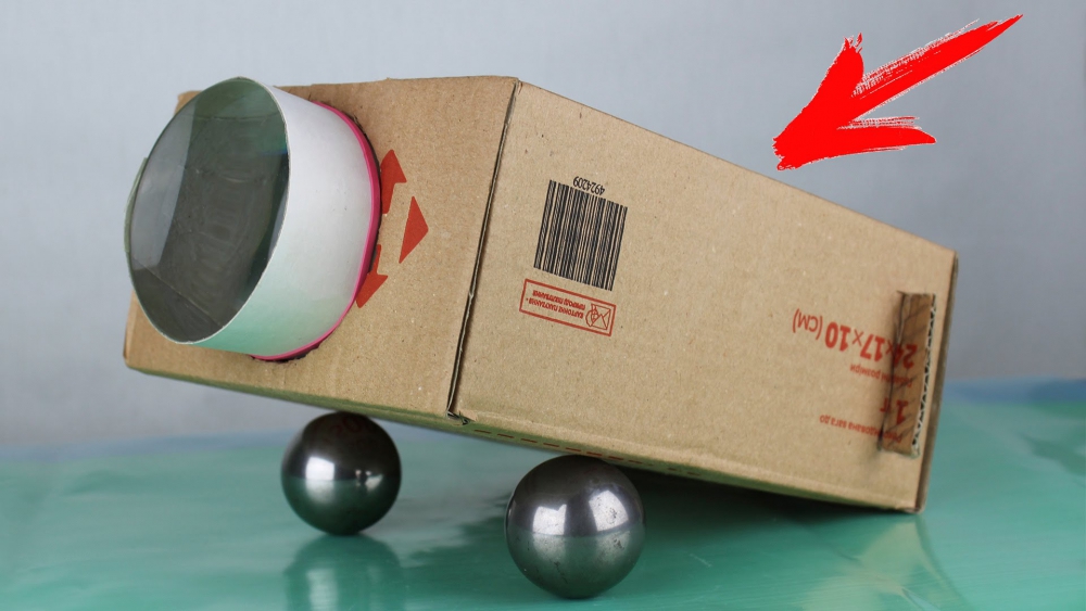
That's the whole projector. See its details in the images below.


Painted box

The lens is applied to the body and outlined with a pencil.
A hole is cut along the line from the pencil with a sharp knife.
A lens is inserted into the hole and glued along the contour


We place the carriage inside the housing box and use the projector

The result we see on the screen greatly depends on the size of the image on it. If the size is reduced, the brightness and clarity of the frame will improve. The image quality in this simple projection device is at the “better than nothing” level. But the reason for this is obvious - more is needed high brightness image source and additional optics.
High-quality homemade projector
Next, we’ll tell you how to make a projector with your own hands, observing all the requirements. You need to start by disassembling the gadget. It is disassembled while maintaining its functionality so that the liquid crystal matrix of the screen is accessible for illumination by an extraneous light source. If you can't do this, then building such a projector is not for you.


Parts used:
- LED power supply board;
- LED 100 W (a light source with minimal dimensions is advantageous);
- fan power supply board;
- fan control board;
- intermediate lens;
- output lens;
- gadget control panel via Wi-Fi;
- two intermediate Fresnel lenses;
- liquid crystal matrix from the gadget.


Heat sink mounted LED


Demonstration of the effectiveness of a Fresnel lens.
An intermediate lens is placed between the LED and the Fresnel lens to reduce light loss


Elimination of projection distortions by suspending a matrix with lenses with horizontal and vertical deviations
And here is the result of the work done. The distance to the screen is 4 meters, the diagonal of the frame on the screen is 100 inches. Everything is clearly visible.


Based on a slide projector
But there is an easier way to create a projector. To do this, you can use a projector for slides that are projected from a sheet of A4 paper (overhead projector). Since all the optics are already in stock, all that remains is to attach the image source to it. It could be a monitor matrix. It will have to be disassembled while still working. Because after installing the matrix in the projector, the monitor, as usual, is connected to the computer. It is best to use a projector that illuminates the slide rather than using reflected light.
What results from this hybridization of a monitor and a projector is shown in the images below.


That's all there is to do. If, of course, you have such a projector. The resulting visibility on the screen is shown in the image below.


The size and quality of the frame on the screen are very good. Moreover, there are projectors for projecting small slides that are comparable to a smartphone screen. They are cheaper. Therefore, you can buy a smartphone with broken screen and a faulty projector for its matrix. And what should happen as a result is already shown above.
You can make your own projector using mobile devices android or laptop monitor. This device is perfect for viewing slides. Also, the homemade projection will make it possible to watch movies. Assembling a simple device is not difficult.
An option on how to make a projector from a phone with your own hands
You can make a projector at home using a regular cardboard box and a phone. This device is not difficult to make with your own hands. To begin with, do preparatory work and stock up necessary tools. The projector will require a cardboard box, a magnifying glass with 10x magnification, a sharp knife, a pencil and electrical tape.
The magnifying glass can be a regular magnifying glass or a Fresnel lens. This item can be purchased at any hardware store.
If desired, the lens can be made at home. This will require certain knowledge and skills. You can use any box as a base, for example a shoe box.
The sequence of creating a projector from a phone:
- First you need to make a hole for the lens. It is performed in the center of the box.
- Next you will need to secure the lens in the hole made. To do this, use electrical tape. In some cases, silicone or special glue is used.
- Next, you will need to install a stand for your smartphone. For this they choose right place. At the same time, the phone must hold tightly and not wobble, so that the image does not end up blurry.
- The resulting device should be tested. To do this, close the curtains in the room. After a trial time, the correct placement of the device becomes clear.
- On the smartphone itself you will need to install special program, which will flip the image, because the lamp bends the picture by 180 degrees.
- On the other side of the box you will need to take care of the hole for charging the phone.

At this point, the homemade cardboard mini projector is considered ready for use. This creates a home theater where you can watch movies with the whole family. In addition, this is a great option for viewing photos with a large group.
A way to make a projector at home from a laptop
A smartphone is a great option for creating a projector. But if you want to improve the quality, you can use another gadget. So it is advised to take into account a laptop or tablet. Because of higher resolution screen video quality will be much better.
When using a laptop, you should understand that the screen resolution will be much better. But the design will be more cumbersome.
The box for building a home theater from a tablet must be large enough. So the length should be at least 50 cm, and the end part is slightly larger than the device screen. It is better to choose a large Soviet magnifying glass.
A hole should be made in the end using a knife. It should be slightly smaller than the magnifying glass itself. The lens is attached using double-sided adhesive tape. Then you should secure the tablet inside the box. It should be taken into account that the lens reverses the image.
Creating a projector from a laptop has its own characteristics. You will need to cut rectangular holes on both ends. The device is placed with the monitor facing down, while the keyboard is located at the top. This placement will help to get the correct image in the final result.
Original 3D projector with your own hands: features of creation
You can make an original 3D projector based on a smartphone. For such a design you will need a plastic pyramid. You can purchase such a device on the Internet, where you can also get acquainted with the dimensions. Then you just need to fix the pyramid on your smartphone strictly in the center and start the required video. The type of design is determined by the purpose of such a device. Therefore, it should be determined in advance.

Purposes of 3d projector:
- You can show a real fairy tale from a technologically progressive future. Such tricks will appeal to both the older and younger generations.
- This design will interest kids and you can show children cartoons.
- A laser slide projector creates the effect of a cinema and you don’t have to spend money on extra costs, this will help you save on hobbies costs.
This design does not require special costs and materials. It is enough to show a little imagination. You will only have to spend money on a plastic pyramid, but this is not a significant expense.
Rules for making a projector with your own hands: main features
Before you start building the projector, you should study its design. Only then can you evaluate your chances of getting the right device. The right projector includes a lens and a lens. They affect the uniform distribution of light. Light must enter the lens at a certain angle.
The image source is usually a liquid crystal matrix. She works for the light. Each pixel increases by several sizes. Therefore, the original image should be as large as possible good quality. The brightness of the projection lamp determines the maximum screen size.
For good image quality, the source material must be FULL HD - this is 1920x1080 pixels.
The simplest video projector is made using a smartphone, a cardboard box and a lens. The box should be larger in size than the gadget, and the diameter of the lens should match the size of the screen. Its focal length determines the distance to the screen.
The principle of arranging a simple projector:
- A hole is made in the box for the lens;
- Any gadget can be secured inside.

The phone frame should be easy to move inside the box. Often, another box, which is smaller in size, is used for this. Reflection of light should be minimal. That is why the inside surface of the box is covered with black applique paper. You can also paint it with matte paint. In some cases, shoe polish may be noticeable. You can also take a thick artist’s canvas
A way to make a magnifying glass at home
The purpose of the lenses is clear. This is a magnifying glass that helps you magnify objects. To make your own lens you will need a plastic bottle, water, plasticine or window putty. When you fill the bottle with water, the magnifying device will be ready, but this is clearly not enough.
Sequential creation of a magnifying glass:
- 2 identical circles are cut out of a plastic bottle.
- Then the two circles will need to be connected using plasticine or window putty. You should not forget to roll out the plasticine before work.
- Next, you will need to cut the straw into two parts and attach it to the surface of the lens.
- One end of the straw is inserted into a slit in the lens, and the other is used to remove air. This will help force water inside the lens. But all connections must be tight.
- Then the lens is lowered into the water and liquid is drawn inside.
After all, the lens is removed and the gap is sealed with sealant. At this point, lens manufacturing is considered complete. For convenience, it is recommended to attach a lens to the structure.
DIY projector screen (video)
To make a projector yourself, you will need to take a magnifying glass, a gadget and cardboard box. After simple manipulations such a filmoscope will project films onto the wall if you make a special elevator. But you can buy ready-made mobile projector Avon. Reviews about it are positive.