How to make color music using LEDs with your own hands. How to make color music using LEDs on your own? How to make a screen for LED light music
Below are schematic diagrams and articles on the topic of “color music” on the radio electronics website and radio hobby website.
What is “color music” and where is it applied, schematic diagrams of homemade devices that relate to the term “color music”.
I propose two simple CMU schemes. The first one was collected many years ago, was repeated by several radio amateurs and did not need any adjustment. The circuit is assembled using only six transistors of the KT315 type, they, of course, can be replaced with others... A simple, easily repeatable color-music installation using symmetrical thyristors and incandescent lighting lamps is described, which can be used to illuminate a hall or dance floor, because summer is coming! It is said about color music... This music set-top box has a relatively high power of lighting lamps, namely: in each channel you can use lamps designed for a voltage of 220 V (one or more), or low-voltage lamps connected in garlands of 220 V. Total power ... Scheme of a simple color music set-top box for working with a tube radio, low-frequency amplifier or tape recorder. Contains a minimum of parts and is not difficult to assemble, a good option for beginner radio amateurs. Connect it to the secondary winding of the output transformer. For power supply... The color music circuit, the operating principle of the installation is based on dividing the spectrum of the sound signal by frequency. To achieve greater variety and richness of the color pattern, instead of the widespread three-color system, it uses a four-color system (red, yellow, blue and violet)... The color-music installation on thyristors develops a power of up to 2...3 kW at the load and can be recommended for color-music accompaniment of variety acts. In this case, it is advisable to mount powerful incandescent lamps in spotlights with color filters, directing them... Installation with pulse-number control of thyristors ensures the convergence of the dynamic ranges of lamp brightness and sound signal level, as well as obtaining light compensation channels without any special electronic devices. The power of each of the three main channels... Homemade color music using triacs, diagram and description of parts for self-production. Triacs are symmetrical thyristors that operate at any voltage polarity at the anode. They are used in household dimmers SRP-0.2-1. The installation is three-channel. The audio frequency signal is supplied to its input through step-up transformer T1, which also performs the functions... I would like to present to your attention a color music set-top box assembled on two synchronous binary counter-dividers (each counter is based on four D-flip-flops), also known as the K561IE10 microcircuit. This design is easily accessible for repetition; the K561IE10 microcircuit can still be bought at a radio store, and radio amateurs will probably have it in stock... The proposed simple devices are designed for creating lighting effects at discos and during various entertainment events. The signals they generate can control several lighting devices, switching them almost randomly Provided... The peak of popularity of color and music installations occurred in the 80s of the last century, now they have somehow almost been forgotten. And yet, time does not stand still, and there are new technologies that can revive “color music” in a new form. Here, for example, are three-color LED RGB strips or garlands... A diagram of a simple homemade three-channel color and music installation with a microphone for responding to sound in a room is given. The device “connects” to the equipment via acoustics, that is, there is a microphone at the input instead of a connector, and it perceives music directly in the room where it is... A three-color LED strip can be used as a screen for a color music installation. The advantage of an RGB LED strip is that it can be positioned in any way, either under a matte screen or, for example, hung as a garland on a Christmas tree. Diagram of a color and music installation... This device is a typical analogue light and music set-top box, like those that were very popular in the 80-90s and are undeservedly forgotten today. The input signal through a separate transformer is fed to four active filters, dividing the signal into four... Schematic diagram of a homemade color music system for three channels, it is based on LM567 tone decoders, S202S02 opto-keys are used for switching. The peak of popularity of color music installations occurred in the 80s of the last century. Now they have somehow almost been forgotten. And yet, time is not worth it... A light-music circuit using LEDs, a simple design based on K561IE16, K176IE4 microcircuits for beginner radio amateurs. In most cases, light and music installations are based on filters that divide the input audio signal into several bands. Then at the output of each of the strips there is a key... An interesting homemade device that changes the color of the LEDs according to the ratio of the frequency components of the audio signal. This device is not a full color music installation, because it works completely differently. The color music installation at the entrance has... Good afternoon, dear radio amateurs. This article appeared thanks to many questions devoted to ionophones of various types, sent to me after the publication of a series of articles on this topic. Especially often questions related to tube ionophones and their improvement and further development... Various options for light-dynamic installations (LDS) are widely presented in amateur radio literature. For the most part, they can be divided according to the principle of operation into two different groups: these are either garland (lantern) switches operating from a clock generator according to a specific program... Good afternoon, dear radio amateurs. Today I would like to continue a short series of articles devoted to ionophones, in response to numerous requests and questions that came after the publication of previous articles on this topic. The proposed version of the ionophone is, in fact, a more powerful version...simple scheme of color music using 220V lamps
Everyone knows and almost everyone assembles this device that flickers and blinks to the music - color music. On the Internet, many search for color music schemes using various queries and they are different everywhere. I present to your attention the diagram below, the appearance of which you see in the pictures. And so, circuit of working color music for 220 Volts on teristors
A simple color scheme
 It will require the bare minimum of parts.
We buy colored incandescent lamps 220V
Considering that the output stage of the color music is made of thyristors, it has a lot of power. If thyristors are placed on heat sinks, then each channel can be loaded with 1000 watts. But for a home, 60-100 watt lamps are quite enough.

Drawing of a printed circuit board for light and music

I did not use laser-iron technology for such a simple board design. I simply printed the image as a mirror image and placed it on the foil.

To prevent the paper from moving, we secure it with tape or something else and mark the places of future holes

We paint the tracks themselves with nitro paint

Any transformer from a Chinese power supply, whether from a radiotelephone or something else, will be suitable as a transformer.
And look at the completely soldered board

We attach the cartridges to the aluminum corner

In addition to the photo sent
In this article we will talk about color music. Probably every beginning radio amateur, and not only others, at one time or another had the desire to assemble color music. What this is, I think, is known to everyone - to put it simply, it is the creation of visual effects that change to the beat of the music.
That part of color music that emits light can be performed using powerful lamps, for example, in a concert setup; if color music is needed for home discos, it can be done using ordinary 220 volt incandescent lamps, and if color music is planned, for example, as computer modding, for everyday use, it can be done with LEDs.

Recently, with the advent of LED strips on sale, color and music consoles using such LED strips are increasingly used. In any case, to assemble Color Musical Installations (CMUs for short) a signal source is required, which can be a microphone with several amplifier stages assembled.

Also, the signal can be taken from the linear output of a device, a computer sound card, from the output of an mp3 player, etc., in this case an amplifier will also be required, for example, two stages on transistors; for this purpose I used KT3102 transistors. The preamplifier circuit is shown in the following figure:

Preamplifier - circuit
The following is a diagram of a single-channel color music with a filter, working in conjunction with a preamplifier (above). In this circuit, the LED flashes along with the bass (low frequencies). To match the signal level, a variable resistor R6 is provided in the color music circuit.

There are also simpler color music circuits that any beginner can assemble, using 1 transistor, and also not requiring a preamplifier; one of these circuits is shown in the picture below:

Color music on a transistor
The pinout diagram for the Jack 3.5 plug is shown in the following figure:

If for some reason it is not possible to assemble a pre-amplifier using transistors, you can replace it with a transformer turned on as a step-up. Such a transformer must produce voltage on the windings of 220/5 Volts. The transformer winding with a smaller number of turns is connected to a sound source, for example, a radio tape recorder, parallel to the speaker, and the amplifier must produce a power of at least 3-5 watts. A winding with a large number of turns is connected to the color music input.
![]()
Of course, color music is not only single-channel, it can be 3, 5 or more multi-channel, when each LED or incandescent lamp blinks while reproducing the frequencies of its range. In this case, the frequency range is set by using filters. In the following circuit, a three-channel color music system (which I recently assembled myself), there are capacitors as filters:

If we wanted to use not individual LEDs in the last circuit, but an LED strip, then the current-limiting resistors R1, R2, R3 should be removed from the circuit. If the strip or LED is used RGB, it must be made with a common anode. If you plan to connect long LED strips, then to control the strip you should use powerful transistors installed on radiators.

Since LED strips are designed for 12 Volt power supply, we should accordingly raise the power supply in the circuit to 12 Volts, and the power supply should be stabilized.
Thyristors in color music
Until now, the article has only talked about color and music devices using LEDs. If there is a need to assemble a digital control unit using incandescent lamps, then thyristors will need to be used to control the brightness of the lamps. What is a thyristor anyway? This is a three-electrode semiconductor device, which accordingly has Anode, Cathode And Control electrode.

KU202 Thyristor
The figure above shows the Soviet thyristor KU202. Thyristors, if you plan to use them with a powerful load, also need to be mounted on a heat sink (radiator). As we see in the figure, the thyristor has a thread with a nut and is attached similarly to powerful diodes. Modern imported ones are simply equipped with a flange with a hole.

One of these thyristor circuits is shown above. This is a three-channel color music circuit with a step-up transformer at the input. When selecting analogue thyristors, you should look at the maximum permissible voltage of the thyristors, in our case for the KU202N it is 400 volts.

The figure shows a similar color music circuit to the one shown above, the main difference in the lower circuit is that there is no diode bridge. Also, LED color music can be built into the system unit. I assembled such a three-channel color music with a preamplifier in a casing from a cider. In this case, the signal was taken from the computer’s sound card using a signal divider, the outputs of which connected active acoustics and color music. It is possible to adjust the signal level, both overall and separately by channel. The preamplifier and color music were powered from a 12 Volt Molex connector (yellow and black wires). The preamplifier and three-channel color music circuits for which they were assembled are shown above. There are other LED color music schemes, for example this one, also three-channel:

Color music on 3 LEDs - diagram
In this circuit, unlike the one I assembled, inductance is used in the mid-frequency channel. For those who want to first assemble something simpler, here is the following diagram for 2 channels:

If you collect color music using lamps, you will have to use light filters, which in turn can be either homemade or purchased. The figure below shows the filters that are commercially available:

Some fans of color and musical effects assemble devices based on microcontrollers. Below is a diagram of four-channel color music on the AVR tiny 15 MK:

The Tiny 15 microcontroller in this circuit can be replaced with tiny 13V, tiny 25V. And at the end of the review, I would like to say on my own that color music using lamps is inferior in terms of entertainment to color music using LEDs, since lamps are more inertial than LEDs. And for self-repetition, I can recommend this one:
Additionally
-
IN: I bought a tape with contacts G, R, B, 12 on it. How to connect?
A: This is the wrong tape, you can throw it awayIN: The firmware loads, but the error “Pragma message...” appears in red letters.
A: This is not an error, but information about the library versionIN: What should I do to connect a ribbon of my own length?
A: Count the number of LEDs, before loading the firmware, change the very first setting in the sketch, NUM_LEDS (the default is 120, replace it with your own). Yes, just replace it and that’s it!!!IN: How many LEDs does the system support?
A: Version 1.1: maximum 450 pieces, version 2.0: 350 piecesIN: How to increase this number?
A: There are two options: optimize the code, take another library for the tape (but you will have to rewrite some of it). Or take Arduino MEGA, it has more memory.IN: Which capacitor should I use to power the tape?
A: Electrolytic. The voltage is 6.3 Volts minimum (more is possible, but the conductor itself will be larger). Capacitance - at least 1000 uF, and the more the better.IN: How to check the tape without Arduino? Does the tape burn without Arduino?
A: The address strip is controlled using a special protocol and works ONLY when connected to a driver (microcontroller) -
YOU CAN ASSEMBLE THE CIRCUIT WITHOUT A POTENTIOMETER! To do this, use the POTENT parameter (in the sketch in the settings block in the settings signal) assign 0. The internal reference voltage reference source of 1.1 Volt will be used. But it will not work at any volume! For the system to work correctly, you will need to select the volume of the incoming audio signal so that everything is beautiful, using the previous two setup steps.
-
Version 2.0 and higher can be used WITHOUT an IR REMOTE, modes are switched with a button, everything else is configured manually before loading the firmware.
-
How to set up another remote control?
Other remote controls have different button codes, use the sketch to determine the button code IR_test(versions 2.0-2.4) or IRtest_2.0(for versions 2.5+), available in the project archive. The sketch sends the codes of the pressed buttons to the port monitor. Next in the main sketch in the section for developers There is a definition block for the remote control buttons, just change the codes to your own. You can calibrate the remote control, but honestly it’s too lazy. -
How to make two volume columns by channel?
To do this, it is not at all necessary to rewrite the firmware; it is enough to cut a long piece of tape into two short ones and restore the broken electrical connections with three wires (GND, 5V, DO-DI). The tape will continue to work as one piece, but now you have two pieces. Of course, the audio plug must be connected with three wires, and the mono mode is disabled in the settings (MONO 0), and the number of LEDs must be equal to the total number on the two segments.
P.S. Look at the first diagram in the diagrams! -
How to reset settings that are stored in memory?
If you've played around with the settings and something goes wrong, you can reset the settings to factory settings. Starting from version 2.4 there is a setting RESET_SETTINGS, set it to 1, flash it, set it to 0 and flash it again. The settings from the sketch will be written to memory. If you are on 2.3, then feel free to upgrade to 2.4, the versions differ only in a new setting that will not affect the operation of the system in any way. In version 2.9 there was a setting SETTINGS_LOG, which outputs the values of settings stored in memory to the port. So, for debugging and understanding.
Almost every novice radio amateur, and not only others, had a desire assemble a color music console or running fire to add variety to your music listening experience in the evening or on holidays. In this article we will talk about a simple color music console assembled on LEDs, which even a novice radio amateur can assemble.
1. The operating principle of color music consoles.
Operation of color music consoles ( CMP, CMU or SDU) is based on frequency division of the spectrum of an audio signal with its subsequent transmission through separate channels low, average And high frequencies, where each channel controls its own light source, the brightness of which is determined by the vibrations of the sound signal. The end result of the console's operation is to obtain a color scheme that matches the piece of music being played.
To obtain a full gamut of colors and the maximum number of color shades, color music consoles use at least three colors:

The frequency spectrum of the audio signal is divided using LC- And RC filters, where each filter is tuned to its own relatively narrow frequency band and passes through only vibrations of this part of the audio range:
1
. Low pass filter(low-pass filter) transmits vibrations with a frequency of up to 300 Hz and the color of its light source is chosen red;
2
. Mid Pass Filter(PSC) transmits 250 – 2500 Hz and the color of its light source is chosen green or yellow;
3
. High pass filter(HPF) transmits from 2500 Hz and above, and the color of its light source is chosen blue.

There are no fundamental rules for choosing the bandwidth or color of the lamps, so each radio amateur can use colors based on the characteristics of his perception of color, and also change the number of channels and frequency bandwidth at his own discretion.
2. Schematic diagram of a color music console.
The figure below shows a diagram of a simple four-channel color and music set-top box assembled using LEDs. The set-top box consists of an input signal amplifier, four channels and a power supply that supplies the set-top box with AC power.

The audio frequency signal is supplied to the contacts PC, OK And General connector X1, and through resistors R1 And R2 goes to the variable resistor R3, which is a regulator of the input signal level. From the middle terminal of the variable resistor R3 sound signal through a capacitor C1 and resistor R4 goes to the input of a pre-amplifier assembled on transistors VT1 And VT2. The use of an amplifier made it possible to use the set-top box with almost any audio source.
From the output of the amplifier, the audio signal is supplied to the upper terminals of trimming resistors R7,R10, R14, R18, which are the load of the amplifier and perform the function of adjusting (tuning) the input signal separately for each channel, and also set the desired brightness of the channel LEDs. From the middle terminals of the trimming resistors, the audio signal is supplied to the inputs of four channels, each of which operates in its own audio range. Schematically, all channels are designed identically and differ only in RC filters.
Per channel higher R7.
The channel bandpass filter is formed by a capacitor C2 and passes only the high-frequency spectrum of the audio signal. Low and medium frequencies do not pass through the filter, since the capacitor resistance for these frequencies is high.

Passing the capacitor, the high-frequency signal is detected by a diode VD1 and is fed to the base of the transistor VT3. The negative voltage appearing at the base of the transistor opens it, and a group of blue LEDs HL1 — HL6 included in its collector circuit are ignited. And the greater the amplitude of the input signal, the stronger the transistor opens, the brighter the LEDs burn. To limit the maximum current through the LEDs, resistors are connected in series with them R8 And R9. If these resistors are missing, the LEDs may fail.
Per channel average frequency signal is supplied from the middle terminal of the resistor R10.
The channel bandpass filter is formed by a circuit С3R11С4, which for low and higher frequencies has significant resistance, therefore, to the base of the transistor VT4 Only mid-frequency oscillations are received. LEDs are included in the collector circuit of the transistor HL7 – HL12 Green colour.
Per channel low frequency signal is supplied from the middle terminal of the resistor R18.
The channel filter is formed by a circuit С6R19С7, which attenuates signals of medium and high frequencies and therefore to the base of the transistor VT6 Only low frequency vibrations are received. The channel load is LEDs HL19 – HL24 Red.
For a variety of colors, a channel has been added to the color music console yellow colors. The channel filter is formed by a circuit R15C5 and operates in the frequency range closer to low frequencies. The input signal to the filter comes from a resistor R14.
The color music console is powered by constant voltage 9V. The power supply unit of the set-top box consists of a transformer T1, diode bridge made on diodes VD5 – VD8, microcircuit voltage stabilizer DA1 type KREN5, resistor R22 and two oxide capacitors C8 And C9.
The alternating voltage rectified by the diode bridge is smoothed by an oxide capacitor C8 and goes to the voltage stabilizer KREN5. From the output 3 microcircuit, a stabilized voltage of 9V is supplied to the set-top box circuit.
To obtain an output voltage of 9V between the negative bus of the power supply and the output 2 chip included resistor R22. By changing the resistance value of this resistor, the desired output voltage is achieved at the pin 3 microcircuits.
3. Details.
The set-top box can use any fixed resistors with a power of 0.25 - 0.125 W. The figure below shows resistor values that use colored stripes to indicate the resistance value:

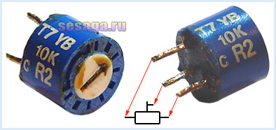
Variable resistor R3 and tuning resistors R7, R10, R14, R18 of any type, as long as they fit the size of the printed circuit board. In the author's version of the design, a domestic variable resistor of the SP3-4VM type and imported trimming resistors were used.
Permanent capacitors can be of any type, and are designed for an operating voltage of at least 16 V. If difficulties arise in purchasing a C7 capacitor with a capacity of 0.3 μF, it can be composed of two connected in parallel with a capacity of 0.22 μF and 0.1 μF.
Oxide capacitors C1 and C6 must have an operating voltage of at least 10 V, capacitor C9 not below 16 V, and capacitor C8 not below 25 V.

Oxide capacitors C1, C6, C8 and C9 have polarity, therefore, when mounting on a breadboard or printed circuit board, this must be taken into account: for Soviet-made capacitors, the positive terminal is indicated on the case; for modern domestic and imported capacitors, the negative terminal is indicated.

Diodes VD1 – VD4 any from the D9 series. A colored stripe is applied to the diode body on the anode side, identifying the letter of the diode.

As a rectifier assembled on diodes VD5 - VD8, a ready-made miniature diode bridge is used, designed for a voltage of 50V and a current of at least 200 mA.

If you use rectifier diodes instead of a ready-made bridge, you will have to slightly adjust the printed circuit board, or even move the diode bridge outside the main board of the set-top box and assemble it on a separate small board.
For self-assembly of the bridge, the diodes are taken with the same parameters as the factory bridge. Any rectifier diodes from the KD105, KD106, KD208, KD209, KD221, D229, KD204, KD205, 1N4001 - 1N4007 series are also suitable. If you use diodes from the KD209 or 1N4001 - 1N4007 series, then the bridge can be assembled directly from the printed circuit board directly on the contact pads of the board.
LEDs are standard with yellow, red, blue and green colors. Each channel uses 6 pieces:

Transistors VT1 and VT2 from the KT361 series with any letter index.

Transistors VT3, VT4, VT5, VT6 from the KT502 series with any letter index.

Voltage stabilizer type KREN5A with any letter index (imported analogue 7805). If you use nine-volt KREN8A or KREN8G (imported analogue 7809), then resistor R22 is not installed. Instead of a resistor, a jumper is installed on the board, which will connect the middle pin of the microcircuit to the negative bus, or this resistor is not provided at all during the manufacture of the board.

To connect the set-top box to the sound source, a three-pin jack connector is used. The cable is taken from a computer mouse.

Power transformer - ready-made or home-made with a power of at least 5 W with a voltage on the secondary winding of 12 - 15 V at a load current of 200 mA.
In addition to the article, watch the first part of the video, which shows the initial stage of assembling a color music console
This ends the first part.
If you are tempted make color music using LEDs, then select the parts and be sure to check the serviceability of diodes and transistors, for example. And we will carry out the final assembly and configuration of the color and music console.
Good luck!
Literature:
1. I. Andrianov “Attacks for radio receivers.”
2. Radio 1990 No. 8, B. Sergeev “Simple color and music consoles.”
3. Operating manual for the “Start” radio designer.