How does a transistor work? Bipolar transistors: switching circuits. Connection circuit for a bipolar transistor with a common emitter What can be done with a transistor
It is perhaps difficult today to imagine the modern world without transistors; in almost any electronics, from radios and televisions, to cars, telephones and computers, they are used in one way or another.
There are two types of transistors: bipolar And field. Bipolar transistors are controlled by current, not voltage. There are high-power and low-power, high-frequency and low-frequency, p-n-p and n-p-n structures... Transistors come in different packages and come in different sizes, ranging from SMD chips (in fact there are much smaller than chips) that are designed for surface mounting, ending with very powerful transistors . Based on power dissipation, there are low-power transistors up to 100 mW, medium-power transistors from 0.1 to 1 W, and high-power transistors greater than 1 W.

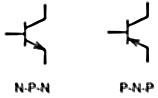
When people talk about transistors, they usually mean bipolar transistors. Bipolar transistors are made of silicon or germanium. They are called bipolar because their work is based on the use of both electrons and holes as charge carriers. Transistors in the diagrams are designated as follows:
One of the outermost regions of the transistor structure is called the emitter. The intermediate region is called the base, and the other extreme region is called the collector. These three electrodes form two p-n junctions: between the base and the collector - the collector, and between the base and the emitter - the emitter. Like a regular switch, a transistor can be in two states - “on” and “off”. But this does not mean that they have moving or mechanical parts; they switch from off to on and back again using electrical signals.

Transistors are designed to amplify, convert and generate electrical oscillations. The operation of a transistor can be illustrated using the example of a plumbing system. Imagine a faucet in the bathroom, one electrode of the transistor is the pipe before the faucet (mixer), the other (second) is the pipe after the faucet, where the water flows out, and the third control electrode is the faucet with which we will turn on the water.
A transistor can be thought of as two diodes connected in series, in the case of NPN the anodes are connected together, and in the case of PNP the cathodes are connected together.

There are transistors of PNP and NPN types, PNP transistors are opened by a voltage of negative polarity, NPN - by a positive one. In NPN transistors, the main charge carriers are electrons, while in PNP they are holes, which are less mobile; accordingly, NPN transistors switch faster.
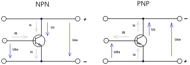
Uke = collector-emitter voltage
Ube = base-emitter voltage
Ic = collector current
Ib = base current
Depending on the states in which the transitions of the transistor are, its operating modes are distinguished. Since the transistor has two transitions (emitter and collector), and each of them can be in two states: 1) open 2) closed. There are four operating modes of the transistor. The main mode is the active mode, in which the collector junction is in the closed state, and the emitter junction is in the open state. Transistors operating in active mode are used in amplification circuits. In addition to the active mode, there is an inverse mode, in which the emitter junction is closed and the collector junction is open, a saturation mode, in which both junctions are open, and a cutoff mode, in which both junctions are closed.
When a transistor operates with high-frequency signals, the time of occurrence of the main processes (the time of movement of carriers from the emitter to the collector) becomes commensurate with the period of change of the input signal. As a result, the transistor's ability to amplify electrical signals deteriorates as frequency increases.
Some parameters of bipolar transistors
Constant/pulse voltage collector - emitter.
Constant collector-base voltage.
Constant voltage emitter - base.
Limit frequency of base current transfer coefficient
Constant/pulse collector current.
Current transfer coefficient
Maximum permissible current
Input impedance
Power dissipation.
Temperature of p-n junction.
Ambient temperature, etc...
Boundary stress Ukeo gr. is the maximum permissible voltage between the collector and emitter, with the base circuit open and the collector current. The voltage at the collector is less than Ukeo gr. characteristic of pulsed operating modes of the transistor at base currents other than zero and the corresponding base currents (for n-p-n transistors the base current is >0, and for p-n-p vice versa, Ib<0).
Bipolar transistors can include unijunction transistors, such as KT117. Such a transistor is a three-electrode semiconductor device with one p-n junction. A unijunction transistor consists of two bases and an emitter.

Recently, composite transistors have often been used in circuits, they are called a pair or Darlington transistors, they have a very high current transfer coefficient, they consist of two or more bipolar transistors, but ready-made transistors are also produced in one package, such as the TIP140. They are turned on with a common collector, if you connect two transistors, they will work as one, the connection is shown in the figure below. The use of load resistor R1 allows you to improve some characteristics of the composite transistor.

Some disadvantages of a compound transistor: low performance, especially the transition from open to closed state. The forward voltage drop across the base-emitter junction is almost twice that of a conventional transistor. Well, of course, you will need more space on the board.
Checking bipolar transistors
Since the transistor consists of two junctions, each of which is a semiconductor diode, you can test the transistor in the same way as you test a diode. The transistor is usually checked with an ohmmeter; both p-n junctions of the transistor are checked: collector - base and emitter - base. To check the direct resistance of the p-n-p transitions of the transistor, the negative terminal of the ohmmeter is connected to the base, and the positive terminal of the ohmmeter is connected alternately to the collector and emitter. To check the reverse resistance of the junctions, the positive terminal of the ohmmeter is connected to the base. When checking n-p-n transistors, the connection is made in reverse: forward resistance is measured when connected to the base of the positive terminal of the ohmmeter, and reverse resistance is measured when connected to the base of the negative terminal. Transistors can also be tested with a digital multimeter in diode testing mode. For NPN, we connect the red “+” probe of the device to the base of the transistor, and alternately touch the black “-” probe to the collector and emitter. The device should show some resistance, approximately from 600 to 1200. Then we change the polarity of connecting the probes, in this case the device should not show anything. For a PNP structure, the checking order will be reversed.
I want to say a few words about MOSFET transistors (metal-oxide-semiconductor field-effect transistor), (Metal Oxide Semiconductor (MOS)) - these are field-effect transistors, not to be confused with ordinary field-effect transistors! Field-effect transistors have three terminals: G - gate, D - drain, S - source. There are N channel and P channel; in the designation of these transistors there is a Schottky diode, it passes current from source to drain, and limits the drain-source voltage.

They are mainly used for switching high currents; they are controlled not by current, like bipolar transistors, but by voltage, and, as a rule, they have a very low open channel resistance; the channel resistance is constant and does not depend on the current. MOSFET transistors are specially designed for key circuits, one might say as a replacement for a relay, but in some cases they can also be amplified; they are used in powerful low-frequency amplifiers.
The advantages of these transistors are as follows:
Minimum control power and high current gain
Better characteristics, such as faster switching speed.
Resistant to large voltage surges.
Circuits where such transistors are used are usually simpler.
Minuses:
They are more expensive than bipolar transistors.
They are afraid of static electricity.
Most often, MOSFETs with an N-channel are used for switching power circuits. The control voltage must exceed the 4V threshold, in general, 10-12V is needed to reliably turn on the MOSFET. The control voltage is the voltage applied between the gate and source to turn on the MOSFET transistor.
The values of most transistor parameters depend on the actual operating mode and temperature, and with increasing temperature, the transistor parameters may change. The reference book contains, as a rule, typical (averaged) dependences of transistor parameters on current, voltage, temperature, frequency, etc.
To ensure reliable operation of transistors, it is necessary to take measures that exclude long-term electrical loads close to the maximum permissible, for example, replacing a transistor with a similar one but of lower power is not worth it, this applies not only to power, but also to other parameters of the transistor. In some cases, to increase power, transistors can be connected in parallel, with emitter connected to emitter, collector to collector, and base to base. Overloads can be caused by various reasons, for example from overvoltage; high-speed diodes are often used to protect against overvoltage.
As for heating and overheating of transistors, the temperature regime of transistors not only affects the value of the parameters, but also determines the reliability of their operation. You should strive to ensure that the transistor does not overheat during operation; in the output stages of amplifiers, transistors must be placed on large radiators. Transistors must be protected from overheating not only during operation, but also during soldering. When tinning and soldering, measures should be taken to prevent overheating of the transistor; it is advisable to hold the transistors with tweezers during soldering to protect them from overheating.
We learned how a transistor works and reviewed manufacturing technologies in general terms. germanium And silicon transistors and figured out how they are marked.
Today we will conduct several experiments and make sure that the bipolar transistor really consists of two diodes, connected back-to-back, and that the transistor is signal amplifier.
We will need a low-power germanium p-n-p transistor from the MP39 - MP42 series, an incandescent lamp rated for a voltage of 2.5 Volts and a power supply of 4 - 5 Volts. In general, for beginning radio amateurs, I recommend assembling a small adjustable one with which you will power your designs.
1. The transistor consists of two diodes.
To verify this, let's assemble a small circuit: the base of the transistor VT1 connect to the minus of the power source, and the collector terminal to one of the terminals of the incandescent lamp EL. Now if the second terminal of the lamp is connected to the positive of the power source, the lamp will light up.
The light bulb came on because we applied direct- the throughput voltage that opened the collector junction and flowed through it direct current collector Ik. The magnitude of this current depends on the resistance filaments lamps and internal resistance power supply.
Now let’s look at the same circuit, but we’ll depict the transistor as a semiconductor plate.
Main charge carriers in the base electrons, overcoming the p-n junction, enter the hole region collector and become irrelevant. Having become minority electrons, the base electrons are absorbed by majority carriers in the hole region of the collector holes. In the same way, holes from the collector region, entering the electronic region of the base, become minority and are absorbed by the main charge carriers in the base electrons.

The base contact connected to the negative pole of the power supply will act almost unlimited quantity electrons, replenishing the decrease in electrons from the base region. And the collector contact, connected to the positive pole of the power source through the lamp filament, is capable of accept the same number of electrons, due to which the concentration of holes in the region will be restored bases.
Thus, the conductivity of the p-n junction will become large and the current resistance will be small, which means that the collector current will flow through the collector junction Ik. And what more there will be this current, then brighter the lamp will light up.
The light bulb will also light if it is connected to the emitter junction circuit. The figure below shows exactly this version of the circuit.

Now let’s change the circuit and base of the transistor a little VT1 connect to plus power supply. In this case, the lamp will not light up, since we have included the p-n junction of the transistor in reverse direction. This means that the resistance of the pn junction has become great and only a very small amount flows through it reverse current collector Ikbo unable to heat a lamp filament EL. In most cases, this current does not exceed a few microamps.

And to finally verify this, let’s again consider a circuit with a transistor depicted as a semiconductor plate.
Electrons located in the region bases, will move to plus power source, moving away from the p-n junction. Holes located in the area collector, will also move away from the p-n junction, moving towards negative pole of the power source. As a result, the border of the regions seems to be will expand, which results in the formation of a zone depleted of holes and electrons, which will provide great resistance to the current.

But, since in each of the areas the base and collector are present non-core charge carriers, then small exchange electrons and holes will still occur between regions. Therefore, a current many times less than direct current will flow through the collector junction, and this current will not be enough to ignite the lamp filament.
2. Operation of the transistor in switching mode.
Let's do another experiment showing one of the operating modes of the transistor.
Between the collector and emitter of the transistor we will connect a power source and the same incandescent lamp connected in series. We connect the plus of the power source to the emitter, and the minus through the filament of the lamp to the collector. The lamp does not light up. Why?

Everything is very simple: if you apply a supply voltage between the emitter and the collector, then, with any polarity, one of the transitions will be in the forward direction, and the other in the reverse direction and will interfere with the flow of current. This is not difficult to see if you look at the following figure.
The figure shows that the base-emitter emitter junction is included in direct direction and is in an open state and is ready to accept an unlimited number of electrons. The base-collector junction, on the contrary, is included in reverse direction and prevents the passage of electrons to the base.
It follows that the main charge carriers in the emitter region holes, repelled by the plus of the power source, rush to the base area and there they are mutually absorbed (recombine) with the main charge carriers in the base electrons. At the moment of saturation, when there are no free charge carriers left on either side, their movement will stop, which means the current stops flowing. Why? Because from the collector's side there will be no recharge electrons.

It turns out that the main charge carriers in the collector holes attracted by the negative pole of the power source, and some of them were mutually absorbed electrons, coming from the minus side of the power source. And at the moment of saturation, when there is no left on both sides free charge carriers, holes, due to their predominance in the collector area, will block further passage of electrons to the base.
Thus, between the collector and the base, a zone depleted of holes and electrons is formed, which will provide great resistance to the current.
Of course, thanks to the magnetic field and thermal effects, a tiny current will still flow, but the strength of this current is so small that it is not capable of heating the lamp filament.
Now let's add to the diagram jumper wire and we will connect the base with the emitter to it. The light bulb connected to the collector circuit of the transistor will not light up again. Why?

Because when the base and emitter are short-circuited with a jumper, the collector junction becomes simply a diode to which the opposite voltage. The transistor is in the off state and only a slight reverse collector current flows through it Ikbo.
Now let's change the circuit a little more and add a resistor Rb resistance 200 - 300 Ohm, and another voltage source Gb in the form of a AA battery.
Connect the negative of the battery through a resistor Rb with a transistor base, plus batteries with an emitter. The lamp came on.

The lamp lit up because we connected a battery between the base and the emitter, and thereby applied it to the emitter junction direct unlocking voltage. The emitter junction opened and went through it straight current, which opened collector junction of the transistor. The transistor opened and along the circuit emitter-base-collector collector current flowing Ik, many times greater than the circuit current emitter-base. And thanks to this current, the light bulb lit up.
If we change the polarity of the battery and apply plus to the base, then the emitter junction will close, and along with it the collector junction will close. A reverse collector current will flow through the transistor Ikbo and the light will go out.
Resistor Rb limits the current in the base circuit. If the current is not limited and all 1.5 volts are applied to the base, then too much current will flow through the emitter junction, which may result in thermal breakdown transition and the transistor will fail. As a rule, for germanium transistors, the unlocking voltage is no more than 0,2 volt, and for silicon no more 0,7 Volt.
And again we will analyze the same circuit, but we will imagine the transistor in the form of a semiconductor plate.
When an unlocking voltage is applied to the base of the transistor, it opens emitter transition and free holes from the emitter begin to be mutually absorbed with electrons bases, creating a small forward base current Ib.

But not all holes introduced from the emitter into the base recombine with its electrons. Typically, the base area is made thin, and in the manufacture of p-n-p structure transistors, the concentration of holes in emitter And collector make many times greater than the electron concentration in database, therefore only a small part of the holes is absorbed by the base electrons.
The bulk of the emitter holes passes through the base and comes under the influence of a higher negative voltage acting in the collector, and together with the collector holes moves to its negative contact, where it is mutually absorbed by the introduced electrons by the negative pole of the power source G.B..
As a result, the resistance of the collector circuit emitter-base-collector decreases and a direct collector current flows in it Ik many times the base current Ib chains emitter-base.
How more more holes are introduced from the emitter into the base, thereby more significantly current in the collector circuit. And, conversely, than less unlocking voltage at the base, so less current in the collector circuit.
If at the moment of operation of the transistor a milliammeter is included in the base and collector circuits, then with the transistor closed there would be practically no currents in these circuits.
When the transistor is open, the base current Ib would be 2-3 mA, and the collector current Ik would be around 60 – 80 mA. All this suggests that the transistor can be current amplifier.
In these experiments, the transistor was in one of two states: open or closed. The transistor switched from one state to another under the influence of the unlocking voltage at the base Ub. This transistor mode is called switching mode or key. This mode of operation of the transistor is used in instruments and automation devices.
Let's finish here, and in the next part we will analyze the operation of a transistor using the example of a simple audio amplifier assembled on a single transistor.
Good luck!
Literature:
1. Borisov V.G - Young radio amateur. 1985
2. E. Iceberg - Transistor?.. It's very simple! 1964
Are bipolar transistors. Switching circuits depend on what kind of conductivity they have (hole or electronic) and the functions they perform.
Classification
Transistors are divided into groups:
- By materials: gallium arsenide and silicon are most often used.
- By signal frequency: low (up to 3 MHz), medium (up to 30 MHz), high (up to 300 MHz), ultra-high (above 300 MHz).
- By maximum dissipation power: up to 0.3 W, up to 3 W, more than 3 W.
- By type of device: three connected layers of semiconductor with alternating changes in the direct and reverse methods of impurity conduction.
How do transistors work?
The outer and inner layers of the transistor are connected to supply electrodes, called emitter, collector and base, respectively.
The emitter and collector do not differ from each other in types of conductivity, but the degree of doping with impurities in the latter is much lower. This ensures an increase in the permissible output voltage.
The base, which is the middle layer, has high resistance because it is made of a lightly doped semiconductor. It has a significant contact area with the collector, which improves the removal of heat generated due to the reverse bias of the junction, and also facilitates the passage of minority carriers - electrons. Although the transition layers are based on the same principle, the transistor is an asymmetrical device. When changing the locations of the outer layers with the same conductivity, it is impossible to obtain similar parameters of the semiconductor device.
Switching circuits are capable of maintaining it in two states: it can be open or closed. In active mode, when the transistor is on, the emitter bias of the junction is made in the forward direction. To visually consider this, for example, on an n-p-n semiconductor triode, voltage should be applied to it from sources, as shown in the figure below.

The boundary at the second collector junction is closed, and no current should flow through it. But in practice the opposite happens due to the close proximity of the transitions to each other and their mutual influence. Since the “minus” of the battery is connected to the emitter, the open junction allows electrons to enter the base zone, where they partially recombine with holes - the majority carriers. A base current I b is formed. The stronger it is, the proportionally greater the output current. Amplifiers using bipolar transistors operate on this principle.
Only diffusion movement of electrons occurs through the base, since there is no action of the electric field there. Due to the insignificant thickness of the layer (microns) and the large size of negatively charged particles, almost all of them fall into the collector area, although the base resistance is quite high. There they are drawn in by the electric field of the transition, which promotes their active transfer. The collector and emitter currents are almost equal to each other, if we neglect the slight loss of charges caused by recombination in the base: I e = I b + I c.
Transistor parameters
- Gain coefficients for voltage U eq /U be and current: β = I to /I b (actual values). Typically, the β coefficient does not exceed 300, but can reach 800 or higher.
- Input impedance.
- Frequency response is the performance of a transistor up to a given frequency, above which transient processes in it do not keep up with changes in the supplied signal.
Bipolar transistor: switching circuits, operating modes
Operating modes differ depending on how the circuit is assembled. The signal must be applied and removed at two points for each case, and only three terminals are available. It follows that one electrode must simultaneously belong to the input and output. This is how any bipolar transistors are turned on. Switching schemes: OB, OE and OK.
1. Scheme with OK
Connection circuit with a common collector: the signal is supplied to a resistor R L, which is also included in the collector circuit. This connection is called a common collector circuit.

This option produces current gain only. The advantage of an emitter follower is the creation of a high input resistance (10-500 kOhm), which allows convenient matching of stages.
2. Scheme with OB
Connection circuit for a bipolar transistor with a common base: the incoming signal enters through C 1, and after amplification it is removed in the output collector circuit, where the base electrode is common. In this case, a voltage gain is created similar to working with OE.

The disadvantage is the low input resistance (30-100 Ohms), and the circuit with OB is used as an oscillator.
3. Scheme with OE
In many cases, when bipolar transistors are used, the switching circuits are predominantly made with a common emitter. The supply voltage is supplied through the load resistor R L, and the negative pole of the external power supply is connected to the emitter.

The alternating signal from the input arrives at the emitter and base electrodes (V in), and in the collector circuit it becomes larger in value (V CE). The main elements of the circuit: a transistor, a resistor R L and an amplifier output circuit with external power. Auxiliary: capacitor C 1, which prevents the passage of direct current into the circuit of the supplied input signal, and resistor R 1, through which the transistor opens.
In the collector circuit, the voltages at the output of the transistor and at the resistor R L are together equal to the value of the EMF: V CC = I C R L + V CE.
Thus, a small signal V in at the input sets the law of changing the direct supply voltage into alternating voltage at the output of the controlled transistor converter. The circuit provides an increase in input current by 20-100 times, and voltage by 10-200 times. Accordingly, power also increases.
Disadvantage of the circuit: low input resistance (500-1000 Ohms). For this reason, problems arise in the formation of the Output impedance of 2-20 kOhm.
The following diagrams demonstrate how a bipolar transistor works. If additional measures are not taken, their performance will be greatly affected by external influences, such as overheating and signal frequency. Also, grounding the emitter creates nonlinear distortion at the output. To increase the reliability of operation, feedback, filters, etc. are connected to the circuit. In this case, the gain decreases, but the device becomes more efficient.
Operating modes
The functions of the transistor are affected by the value of the connected voltage. All operating modes can be shown if the previously presented circuit for connecting a bipolar transistor with a common emitter is used.
1. Cut-off mode
This mode is created when the voltage value V BE decreases to 0.7 V. In this case, the emitter junction closes and there is no collector current, since there are no free electrons in the base. Thus, the transistor is switched off.
2. Active mode
If a voltage sufficient to turn on the transistor is applied to the base, a small input current appears and an increased output current appears, depending on the magnitude of the gain. Then the transistor will work as an amplifier.
3. Saturation mode
The mode differs from the active one in that the transistor opens completely and the collector current reaches the maximum possible value. Its increase can only be achieved by changing the applied EMF or load in the output circuit. When the base current changes, the collector current does not change. Saturation mode is characterized by the fact that the transistor is extremely open, and here it serves as a switch in the on state. Circuits for switching on bipolar transistors when combining cutoff and saturation modes make it possible to create electronic switches with their help.
All operating modes depend on the nature of the output characteristics shown in the graph.

They can be clearly demonstrated if a circuit for switching on a bipolar transistor with an OE is assembled.
If you plot on the ordinate and abscissa axes the segments corresponding to the maximum possible collector current and the value of the supply voltage V CC, and then connect their ends to each other, you will get a load line (red). It is described by the expression: I C = (V CC - V CE)/R C. It follows from the figure that the operating point, which determines the collector current IC and voltage V CE, will shift along the load line from bottom to top as the base current I V increases.
The area between the V CE axis and the first output characteristic (shaded), where I B = 0, characterizes the cutoff mode. In this case, the reverse current I C is negligible, and the transistor is closed.
The uppermost characteristic at point A intersects with the direct load, after which, with a further increase in I B, the collector current no longer changes. The saturation zone on the graph is the shaded area between the I C axis and the steepest characteristic.
How does a transistor behave in different modes?
The transistor operates with variable or constant signals entering the input circuit.
Bipolar transistor: switching circuits, amplifier
For the most part, the transistor serves as an amplifier. An alternating signal at the input causes its output current to change. Here you can use schemes with OK or with OE. The signal requires a load in the output circuit. Typically a resistor is used in the output collector circuit. If it is chosen correctly, the output voltage will be significantly higher than the input.
The operation of the amplifier is clearly visible in the timing diagrams.

When pulse signals are converted, the mode remains the same as for sinusoidal ones. The quality of conversion of their harmonic components is determined by the frequency characteristics of the transistors.
Operation in switching mode
Designed for contactless switching of connections in electrical circuits. The principle is to change the resistance of the transistor in steps. The bipolar type is quite suitable for the requirements of the key device.
Conclusion
Semiconductor elements are used in electrical signal conversion circuits. Universal capabilities and large classification allow bipolar transistors to be widely used. Switching circuits determine their functions and operating modes. Much also depends on the characteristics.
The basic switching circuits of bipolar transistors amplify, generate and convert input signals, and also switch electrical circuits.
All experiments use KT315B transistors, D9B diodes, and 2.5V x 0.068A miniature incandescent lamps. Headphones are high-impedance, type TON-2. Variable capacitor - any, with a capacity of 15...180 pF. The power battery consists of two 4.5V 3R12 batteries connected in series. The lamps can be replaced with series-connected AL307A LEDs and a 1 kOhm resistor.
EXPERIMENT 1
ELECTRICAL DIAGRAM (conductors, semiconductors and insulators)
Electric current is the directed movement of electrons from one pole to another under the influence of voltage (9 V battery).
All electrons have the same negative charge. Atoms of different substances have different numbers of electrons. Most electrons are tightly bound to atoms, but there are also so-called “free” or valence electrons. If voltage is applied to the ends of the conductor, free electrons will begin to move towards the positive pole of the battery.
In some materials, electrons move relatively freely and are called conductors; in others, movement is difficult, they are called semiconductors; thirdly, it is generally impossible; such materials are called insulators, or dielectrics.
Metals are good conductors of current. Substances such as mica, porcelain, glass, silk, paper, cotton are classified as insulators.
Semiconductors include germanium, silicon, etc. These substances become conductors under certain conditions. This property is used in the production of semiconductor devices - diodes, transistors.

Rice. 1. Determination of water conductivity
This experiment demonstrates the operation of a simple electrical circuit and the differences in conductivity between conductors, semiconductors, and dielectrics.
Assemble the circuit as shown in Fig. 1, and bring the bare ends of the wires to the front of the board. Connect the bare ends together, the light bulb will light. This indicates that an electric current is passing through the circuit.
Using two wires you can test the conductivity of various materials. To accurately determine the conductivity of certain materials, special instruments are required. (The brightness of the light bulb can only determine whether the material being tested is a good or bad conductor.)
Connect the bare ends of the two conductors to a piece of dry wood a short distance apart. The light will not light up. This means that dry wood is a dielectric. If the bare ends of two conductors are connected to aluminum, copper or steel, the light bulb will light. This suggests that metals are good conductors of electric current.
Dip the bare ends of the conductors into a glass of tap water (Fig. 1, a). The light is not on. This means that water is a poor conductor of current. If you add a little salt to the water and repeat the experiment (Fig. 1, b), the light bulb will light, which indicates the flow of current in the circuit.
The 56 ohm resistor in this circuit and in all subsequent experiments serves to limit the current in the circuit.
EXPERIMENT 2
DIODE ACTION
The purpose of this experiment is to clearly demonstrate that the diode conducts current well in one direction and does not conduct in the opposite direction.
Assemble the circuit as shown in Fig. 2, a. The lamp will light up. Rotate the diode 180° (Fig. 2, b). The light will not light up.
Now let’s try to understand the physical essence of the experiment.

Rice. 2. Action of a semiconductor diode in an electronic circuit.
The semiconductor substances germanium and silicon each have four free, or valence, electrons. The atoms of the semiconductor are bonded into dense crystals (crystal lattice) (Fig. 3, a).

Rice. 3. Crystal lattice of semiconductors.
If an impurity is introduced into a semiconductor having four valence electrons, for example arsenic, which has five valence electrons (Fig. 3, b), then the fifth electron in the crystal will be free. Such impurities provide electronic conductivity, or n-type conductivity.
Impurities that have a lower valency than semiconductor atoms have the ability to attach electrons to themselves; such impurities provide hole conductivity, or p-type conductivity (Fig. 3, c).

Rice. 4. p-n junctions in a semiconductor diode.
A semiconductor diode consists of a junction of p- and n-type materials (p-n junction) (Fig. 4, a). Depending on the polarity of the applied voltage, the p-n junction can either facilitate (Fig. 4, d) or hinder (Fig. 4, c) the passage of electric current. At the interface of two semiconductors, even before applying external voltage, a binary electric layer with a local electric field of intensity E 0 is created (Fig. 4, b).
If an alternating current is passed through the diode, then the diode will pass only the positive half-wave (Fig. 4 d), and the negative will not pass (see Fig. 4, c). The diode thus converts, or “rectifies,” alternating current into direct current.
EXPERIMENT 3
HOW DOES A TRANSISTOR WORK
This experiment clearly demonstrates the basic function of a transistor, which is a current amplifier. A small control current in the base circuit can cause a large current in the emitter-collector circuit. By changing the resistance of the base resistor, you can change the collector current.

Assemble the circuit (Fig. 5). Place resistors in the circuit one by one: 1 MOhm, 470 kOhm, 100 kOhm, 22 kOhm, 10 kOhm. You will notice that with 1 MΩ and 470 kΩ resistors the light bulb does not light; 100 kOhm - the light bulb barely lights up; 22 kOhm - the light bulb burns brighter; Full brightness is observed when connecting a 10 kOhm base resistor.
|
Rice. 6. Transistor with n-p-n structure. |
Rice. 7. Transistor with p-n-p structure. |


A transistor is essentially two semiconductor diodes that have one common area - the base. If in this case the region with p-conductivity turns out to be common, then a transistor with an n-p-n structure will be obtained (Fig. 6); if the general area is with n-conductivity, then the transistor will have a p-n-p structure (Fig. 7).
The region of the transistor that emits (emigrates) current carriers is called the emitter; The area that collects current carriers is called a collector. The area enclosed between these areas is called the base. The transition between the emitter and the base is called the emitter, and between the base and the collector is called the collector.
In Fig. Figure 5 shows the inclusion of an n-p-n transistor in an electrical circuit.
When a pnp transistor is connected to the circuit, the polarity of battery B is reversed.
For currents flowing through a transistor, there is a relationship
I e = I b + I k
Transistors are characterized by a current gain, denoted by the letter β, which is the ratio of the increment in the collector current to the change in the base current.
The value of β ranges from several tens to several hundred units depending on the type of transistor.
EXPERIMENT 4
CONDENSER PROPERTIES
Having studied the principle of operation of a transistor, you can demonstrate the properties of a capacitor. Assemble the circuit (Fig. 8), but do not attach the 100 µF electrolytic capacitor. Then connect it to position A for a while (Fig. 8, a). The light will come on and go off. This indicates that a capacitor charging current was flowing in the circuit. Now place the capacitor in position B (Fig. 8, b), but do not touch the terminals with your hands, otherwise the capacitor may discharge. The light will light up and go out, indicating that the capacitor has discharged. Now place the capacitor again in position A. It is charged. Place the capacitor aside for a while (10 s) on the insulating material, then place it in position B. The light will turn on and off. From this experiment it is clear that the capacitor is capable of accumulating and storing electric charge for a long time. The accumulated charge depends on the capacitance of the capacitor.
|
Rice. 8. Diagram explaining the principle of operation of a capacitor. |
Rice. 9. Change in voltage and current across the capacitor over time. |


Charge the capacitor by placing it in position A, then discharge it by connecting conductors with bare ends to the terminals of the capacitor (hold the conductor by the insulated part!), and place it in position B. The light bulb will not light up. As can be seen from this experiment, a charged capacitor acts as a power source (battery) in the base circuit, but after using the electric charge, the light bulb goes out. In Fig. Figure 9 shows the time dependences of: capacitor charge voltage; charge current flowing in the circuit.
EXPERIMENT 5
TRANSISTOR AS A SWITCH
Assemble the circuit according to Fig. 10, but do not install resistor R1 and transistor T1 into the circuit yet. Key B must be connected to the circuit at points A and E so that the connection point of resistors R3, R1 can be connected to a common wire (negative bus of the printed circuit board).

Rice. 10. The transistor in the circuit works like a switch.
Connect the battery, the light in the T2 collector circuit will light up. Now close the circuit with switch B. The light will go out, since the switch connects point A to the negative bus, thereby reducing the potential of point A, and therefore the potential of the T2 base. If the switch is returned to its original position, the light will come on. Now disconnect the battery and connect T1, do not connect resistor R1. Connect the battery, the light will come on again. As in the first case, transistor T1 is open and electric current passes through it. Now place resistor R1 (470 kOhm) at points C and D. The light will go out. Remove the resistor and the light will come back on.
When the voltage at the T1 collector drops to zero (when installing a 470 kOhm resistor), the transistor opens. The base of transistor T2 is connected through T1 to the negative bus, and T2 closes. The light goes out. Thus, transistor T1 acts as a switch.
In previous experiments the transistor was used as an amplifier, now it is used as a switch.
The possibilities of using a transistor as a key (switch) are given in experiments 6, 7.
EXPERIMENT 6
ALARM
A feature of this circuit is that transistor T1, used as a key, is controlled by photoresistor R2.
The photoresistor included in this kit changes its resistance from 2 kOhms in strong lighting to several hundred kOhms in the dark.
Assemble the circuit according to Fig. 11. Depending on the lighting of the room where you are conducting the experiment, select resistor R1 so that the light bulb burns normally without dimming the photoresistor.

Rice. 11. Alarm circuit based on a photoresistor.
The state of transistor T1 is determined by a voltage divider consisting of resistor R1 and photoresistor R2.
If the photoresistor is illuminated, its resistance is low, transistor T1 is closed, and there is no current in its collector circuit. The state of transistor T2 is determined by applying a positive potential to the base of T2 by resistors R3 and R4. Consequently, transistor T2 opens, collector current flows, and the light bulb lights up.
When the photoresistor is darkened, its resistance increases greatly and reaches a value when the divider supplies a voltage to the base of T1 sufficient to open it. The voltage at the collector T1 drops almost to zero, through resistor R4 it turns off transistor T2, and the light goes out.
In practice, in such circuits, other actuators (bell, relay, etc.) can be installed in the collector circuit of transistor T2.
In this and subsequent circuits, a photoresistor of the SF2-9 type or similar can be used.
EXPERIMENT 7
AUTOMATIC LIGHT SWITCH
Unlike experiment 6, in this experiment, when photoresistor R1 is dimmed, the light bulb lights up (Fig. 12).

Rice. 12. Circuit that turns on the light automatically.
When light hits the photoresistor, its resistance decreases greatly, which leads to the opening of transistor T1, and consequently to the closing of T2. The light is not on.
In the dark, the light turns on automatically.
This property can be used to turn lamps on and off depending on the light level.
EXPERIMENT 8
SIGNAL DEVICE
A distinctive feature of this scheme is its high sensitivity. In this and a number of subsequent experiments, a combined connection of transistors (composite transistor) is used (Fig. 13).

Rice. 13. Optoelectronic signaling device.
The operating principle of this circuit is no different from the circuit. At a certain value of the resistance of resistors R1 + R2 and the resistance of photoresistor R3, current flows in the base circuit of transistor T1. A current also flows in the collector circuit T1, but 3 times greater than the base current T1. Let us assume that (β = 100. All current flowing through the emitter T1 must pass through the emitter-base junction T2. Then the collector current T2 is β times greater than the collector current of T1, the collector current of T1 is β times the base current of T1, the collector current of T2 is approximately 10,000 times the base current of T1. Thus, the composite transistor can be considered as a single transistor with a very high gain and high sensitivity. The second feature of a composite transistor is that transistor T2 must be quite powerful, while the transistor T1 controlling it may be low-power, since the current passing through it is 100 times less than the current passing through T2.
The performance of the circuit shown in Fig. 13, is determined by the illumination of the room where the experiment is being carried out, so it is important to select the resistance R1 of the upper arm divider so that in a lit room the light bulb does not burn, but burns when the photoresistor is dimmed by hand, the room is darkened with curtains, or when the light is turned off if the experiment is carried out in the evening.
EXPERIMENT 9
HUMIDITY SENSOR
In this circuit (Fig. 14), a compound transistor with high sensitivity is also used to determine the moisture content of the material. The base bias of T1 is provided by resistor R1 and two conductors with bare ends.
Check the electrical circuit by lightly squeezing the bare ends of two conductors with the fingers of both hands, without connecting them to each other. The resistance of the fingers is enough to trigger the circuit, and the light bulb lights up.

Rice. 14. Humidity sensor circuit. The bare ends of the conductors penetrate the blotting paper.
Now pass the bare ends through blotting paper at a distance of approximately 1.5-2 cm, attach the other ends to the diagram according to Fig. 14. Next, dampen the blotting paper between the wires with water. The light comes on (In this case, the decrease in resistance occurred due to the dissolution of the salts in the paper with water.).
If blotting paper is soaked in a saline solution, and then dried and the experiment is repeated, the efficiency of the experiment increases and the ends of the conductors can be separated over a greater distance.
EXPERIMENT 10
SIGNAL DEVICE
This circuit is similar to the previous one, the only difference is that the lamp lights up when the photoresistor is illuminated and goes out when it is darkened (Fig. 15).

Rice. 15. Signaling device on a photoresistor.
The circuit works as follows: with normal lighting of the photoresistor R1, the light bulb will light up, since the resistance of R1 is low, the transistor T1 is open. When the light is turned off, the light will go out. Light from a flashlight or lit matches will cause the light bulb to light again. The sensitivity of the circuit is adjusted by increasing or decreasing the resistance of resistor R2.
EXPERIMENT 11
PRODUCTS COUNTER
This experiment should be carried out in a semi-darkened room. All the time the light falls on the photoresistor, the indicator light L2 is on. If you place a piece of cardboard between the light source (bulb L1 and the photoresistor, light bulb L2 goes out. If you remove the cardboard, light bulb L2 lights up again (Fig. 16).

Rice. 16. Product counter.
For the experiment to be successful, you need to adjust the circuit, i.e. select the resistance of resistor R3 (the most suitable in this case is 470 Ohms).
This scheme can practically be used to count a batch of products on a conveyor belt. If the light source and photoresistor are placed in such a way that a batch of products passes between them, the circuit is switched on and off as the flow of light is interrupted by passing products. Instead of the L2 indicator light, a special counter is used.
EXPERIMENT 12
SIGNAL TRANSMISSION USING LIGHT

Rice. 23. Transistor frequency divider.
Transistors T1 and T2 open alternately. The control signal is sent to the flip-flop. When transistor T2 is open, light bulb L1 does not light up. Lamp L2 lights up when transistor T3 is open. But transistors T3 and T4 open and close alternately, therefore, lamp L2 lights up with every second control signal sent by the multivibrator. Thus, the burning frequency of light bulb L2 is 2 times less than the burning frequency of light bulb L1.
This property can be used in an electric organ: the frequencies of all notes in the upper octave of the organ are divided in half and a tone is created an octave lower. The process may be repeated.
EXPERIMENT 18
SCHEME “AND” BY UNITS
In this experiment, a transistor is used as a switch and a light bulb is the output indicator (Figure 24).
This circuit is logical. The light will light if there is a high potential at the base of the transistor (point C).
Let's say points A and B are not connected to the negative bus, they have a high potential, therefore, at point C there is also a high potential, the transistor is open, the light bulb is on.

Rice. 24. Logic element 2I on a transistor.
Let’s assume conditionally: high potential - logical “1” - the light is on; low potential - logical “0” - the light does not light.
Thus, if there are logical “1” at points A and B, there will also be a “1” at point C.
Now connect point A to the negative bus. Its potential will become low (fall to “0” V). Point B has high potential. Current will flow through the circuit R3 - D1 - battery. Therefore, at point C there will be a low potential or “0”. The transistor is closed, the light does not light.
Let's connect point B to ground. The current now flows through the circuit R3 - D2 - battery. The potential at point C is low, the transistor is closed, the light bulb does not light up.
If both points are connected to ground, point C will also have a low potential.
Similar circuits can be used in an electronic examiner and other logic circuits, where the output signal will only be generated if there are simultaneous signals in two or more input channels.
Possible states of the circuit are shown in the table.
Truth table of the AND circuit
EXPERIMENT 19
"OR" SCHEME BY UNITS
This scheme is the opposite of the previous one. In order for there to be “0” at point C, it is necessary that there should also be “0” at points A and B, that is, points A and B must be connected to a negative bus. In this case, the transistor will close and the light will go out (Fig. 25).
If now only one of the points, A or B, is connected to the negative bus, then at point C there will still be a high level, i.e. “1”, the transistor is open, the light is on.

Rice. 25. Logic element 2OR on a transistor.
When point B is connected to the negative bus, the current will flow through R2, D1 and R3. No current will flow through diode D2, since it is turned on in the opposite direction for conductivity. At point C there will be about 9 V. The transistor is open, the light bulb is on.
Now we connect point A to the negative bus. The current will flow through R1, D2, R3. The voltage at point C will be about 9 V, the transistor is open, the light bulb is on.
OR circuit truth table
EXPERIMENT 20
CIRCUIT "NOT" (INVERTER)
This experiment demonstrates the operation of a transistor as an inverter - a device capable of changing the polarity of the output signal relative to the input signal to the opposite one. In the experiments, the transistor was not part of the operating logic circuits; it only served to turn on the light bulb. If point A is connected to the negative bus, then its potential will drop to “0”, the transistor will close, the light will go out, and at point B there will be a high potential. This means logical “1” (Fig. 26).

Rice. 26. The transistor works as an inverter.
If point A is not connected to the negative bus, i.e. at point A there is “1”, then the transistor is open, the light bulb is on, the voltage at point B is close to “0” or it is a logical “0”.
In this experiment, a transistor is an integral part of a logic circuit and can be used to convert an OR circuit to a NOR circuit and an AND circuit to a NAND circuit.
Truth table of NOT circuit
EXPERIMENT 21
"AND-NOT" SCHEME
This experiment combines two experiments: 18 - AND circuit and 20 - NOT circuit (Fig. 27).
This circuit functions similarly to the circuit, forming a “1” or “0” on the basis of a transistor.

Rice. 27. Logic element 2I-NOT on a transistor.
The transistor is used as an inverter. If a “1” appears at the base of the transistor, then the output point is “0” and vice versa.
If the potentials at point D are compared with the potentials at point C, it is clear that they are inverted.
NAND circuit truth table
EXPERIMENT 22
"OR-NOT" SCHEME
This experiment combines two experiments: - OR circuit and - NOT circuit (Fig. 28).

Rice. 28. Logic element 2OR-NOT on a transistor.
The circuit functions exactly the same as in experiment 20 (a “0” or “1” is generated at the base of the transistor). The only difference is that the transistor is used as an inverter: if “1” is at the input of the transistor, then “0” is at its output and vice versa.
Truth table of NOR circuit
EXPERIMENT 23
“AND-NOT” CIRCUIT ASSEMBLED WITH TRANSISTORS
This circuit consists of two NOT logic circuits, the transistor collectors of which are connected at point C (Fig. 29).
If both points A and B are connected to a negative bus, then their potentials will become equal to “0”. The transistors will close, at point C there will be a high potential, the light bulb will not light up.

Rice. 29. Logic element 2I-NOT.
If only point A is connected to the negative bus, at point B there is a logical “1”, T1 is closed, and T2 is open, the collector current flows, the light is on, at point C there is a logical “0”.
If point B is connected to the negative bus, then the output will also be “0”, the light will be on, in this case T1 is open, T2 is closed.
And finally, if points A and B are logic "1" (not connected to the negative bus), both transistors are open. Their collectors are “0”, current flows through both transistors, the light bulb is on.
NAND circuit truth table
EXPERIMENT 24
PHONE SENSOR AND AMPLIFIER
In the experimental circuit, both transistors are used as an audio signal amplifier (Fig. 30).

Rice. 30. Inductive phone sensor.
The signals are captured and applied to the base of transistor T1 using an inductive coil L, then they are amplified and sent to the phone. When you have finished assembling the circuit on the board, place a ferrite rod near the phone perpendicular to the incoming wires. Speech will be heard.
In this scheme and in the future, a ferrite rod with a diameter of 8 mm and a length of 100-160 mm, grade 600NN, is used as an inductive coil L. The winding contains approximately 110 turns of insulated copper wire with a diameter of 0.15..0.3 mm, type PEL or PEV.
EXPERIMENT 25
MICROPHONE AMPLIFIER
If an extra telephone is available (Fig. 31), it can be used instead of the inductor in the previous experiment. As a result, we will have a sensitive microphone amplifier.

Rice. 31. Microphone amplifier.
Within the assembled circuit, you can get something like a two-way communication device. Phone 1 can be used as a receiving device (connection at point A), and phone 2 can be used as an output device (connection at point B). In this case, the second ends of both phones must be connected to the negative bus.
EXPERIMENT 26
PLAYER AMPLIFIER
Using a gramophone amplifier (Fig. 32), you can listen to recordings without disturbing the peace of others.
The circuit consists of two audio amplification stages. The input signal is the signal coming from the pickup.

Rice. 32. Amplifier for player.
In the diagram, the letter A indicates the sensor. This sensor and capacitor C2 are a capacitive voltage divider to reduce the initial volume. Trimmer capacitor C3 and capacitor C4 are secondary voltage dividers. Using C3 you can adjust the volume.
EXPERIMENT 27
"ELECTRONIC VIOLIN"
Here the multivibrator circuit is designed for producing electronic music. The scheme is similar. The main difference is that the base bias resistor of transistor T1 is variable. A 22 kΩ resistor (R2) in series with the variable resistor provides the minimum base bias resistance for T1 (Figure 33).

Rice. 33. Multivibrator for creating music.
EXPERIMENT 28
FLASHING BUZZER MORSE
In this circuit, the multivibrator is designed to generate pulses with a tone frequency. The light comes on when the circuit is powered on (Fig. 34).
The telephone in this circuit is connected to the circuit between the collector of transistor T2 through capacitor C4 and the negative bus of the board.

Rice. 34. Generator for learning Morse code.
Use this chart to practice learning Morse code.
If you are not satisfied with the sound tone, swap capacitors C2 and C1.
EXPERIMENT 29
METRONOME
A metronome is a device for setting rhythm (tempo), for example, in music. For these purposes, a pendulum metronome was previously used, which provided both a visual and audible indication of the tempo.
In this circuit, the indicated functions are performed by a multivibrator. The tempo frequency is approximately 0.5 s (Fig. 35).

Rice. 35. Metronome.
Thanks to the telephone and the indicator light, it is possible to hear and visually feel the given rhythm.
EXPERIMENT 30
AUDIBLE ALARM DEVICE WITH AUTOMATIC RETURN TO STARTING POSITION
This circuit (Fig. 36) demonstrates the use of a one-shot device, the operation of which is described in experiment 14. In the initial state, transistor T1 is open and T2 is closed. The phone is used here as a microphone. Whistling into the microphone (you can just blow) or light tapping excites alternating current in the microphone circuit. Negative signals, arriving at the base of transistor T1, close it, and therefore open transistor T2, a current appears in the collector circuit T2, and the light bulb lights up. At this time, capacitor C1 is charged through resistor R1. The voltage of the charged capacitor C2 is sufficient to open the transistor T1, i.e. the circuit returns to its original state spontaneously, and the light goes out. The lamp burns for about 4 seconds. If capacitors C2 and C1 are swapped, the burning time of the light bulb will increase to 30 s. If resistor R4 (1 kOhm) is replaced with 470 kOhm, the time will increase from 4 to 12 s.

Rice. 36. Acoustic signaling device.
This experiment can be presented as a magic trick that can be performed among friends. To do this, you need to remove one of the phone's microphones and place it under the board near the light bulb so that the hole in the board coincides with the center of the microphone. Now, if you blow on a hole in the board, it will seem like you are blowing on a light bulb and therefore it will light up.
EXPERIMENT 31
AUDIBLE ALARM DEVICE WITH MANUAL RESET
This circuit (Fig. 37) is similar in principle to the previous one, with the only difference being that when switching, the circuit does not automatically return to its original state, but is done using switch B.

Rice. 37. Acoustic warning device with manual reset.
The circuit's readiness state or initial state will be when transistor T1 is open, T2 is closed, and the lamp is not lit.
A light whistle into the microphone gives a signal that turns off transistor T1, while opening transistor T2. The warning light comes on. It will burn until transistor T2 closes. To do this, it is necessary to short-circuit the base of transistor T2 to the negative bus (“ground”) using key B. Other actuators, such as relays, can be connected to similar circuits.
EXPERIMENT 32
THE SIMPLE DETECTOR RECEIVER
A novice radio amateur should begin designing radio receivers with the simplest designs, for example, with a detector receiver, the diagram of which is shown in Fig. 38.
The detector receiver works as follows: electromagnetic waves sent into the air by radio stations, crossing the receiver antenna, induce a voltage in it with a frequency corresponding to the frequency of the radio station signal. The induced voltage enters the input circuit L, C1. In other words, this circuit is called resonant, since it is pre-tuned to the frequency of the desired radio station. In the resonant circuit, the input signal is amplified tens of times and then goes to the detector.

Rice. 38. Detector receiver.
The detector is assembled on a semiconductor diode, which serves to rectify the modulated signal. The low-frequency (sound) component will pass through the headphones, and you will hear speech or music, depending on the transmission of that radio station. The high-frequency component of the detected signal, bypassing the headphones, will pass through capacitor C2 to ground. The capacitance of capacitor C2 determines the degree of filtering of the high-frequency component of the detected signal. Typically, the capacitance of capacitor C2 is chosen so that for audio frequencies it represents a large resistance, and for the high-frequency component its resistance is small.
As capacitor C1, you can use any small-sized capacitor of variable capacity with a measurement range of 10...200 pF. In this designer, a ceramic tuning capacitor of the KPK-2 type with a capacity of 25 to 150 pF is used to adjust the circuit.
Inductor L has the following parameters: number of turns - 110±10, wire diameter - 0.15 mm, type - PEV-2, frame diameter of insulating material - 8.5 mm.
ANTENNA
A correctly assembled receiver begins to work immediately when an external antenna is connected to it, which is a piece of copper wire with a diameter of 0.35 mm, 15-20 m long, suspended on insulators at a certain height above the ground. The higher the antenna is above the ground, the better the reception of radio signals will be.
GROUNDING
The reception volume increases if grounding is connected to the receiver. The ground wire should be short and have low resistance. Its end is connected to a copper pipe going deep into the ground.
EXPERIMENT 33
DETECTOR RECEIVER WITH LOW FREQUENCY AMPLIFIER
This circuit (Fig. 39) is similar to the previous circuit of the detector receiver with the only difference that a simple low-frequency amplifier, assembled on transistor T, is added here. The low-frequency amplifier serves to increase the power of the signals detected by the diode. The oscillatory circuit tuning circuit is connected to the diode through capacitor C2 (0.1 μF), and resistor R1 (100 kOhm) provides the diode with a constant bias.

Rice. 39. Detector receiver with single-stage ULF.
For normal operation of the transistor, a 9 V power supply is used. Resistor R2 is necessary to supply voltage to the base of the transistor to create the required operating mode.
For this circuit, as in the previous experiment, an external antenna and ground are required.
EXPERIMENT 34
SIMPLE TRANSISTOR RECEIVER
The receiver (Fig. 40) differs from the previous one in that instead of diode D, a transistor is installed, which simultaneously works both as a detector of high-frequency oscillations and as a low-frequency amplifier.

Rice. 40. Single-transistor receiver.
Detection of a high-frequency signal in this receiver is carried out in the base-emitter section, therefore such a receiver does not require a special detector (diode). The transistor with the oscillatory circuit is connected, as in the previous circuit, through a capacitor with a capacity of 0.1 μF and is decoupling. Capacitor C3 serves to filter the high-frequency component of the signal, which is also amplified by the transistor.
EXPERIMENT 35
REGENERATIVE RECEIVER
This receiver (Fig. 41) uses regeneration to improve the sensitivity and selectivity of the circuit. This role is performed by coil L2. The transistor in this circuit is connected slightly differently than in the previous one. The signal voltage from the input circuit is supplied to the base of the transistor. The transistor detects and amplifies the signal. The high-frequency component of the signal does not immediately enter the filter capacitor C3, but first passes through the feedback winding L2, which is located on the same core as the loop coil L1. Due to the fact that the coils are placed on the same core, there is an inductive coupling between them, and part of the amplified voltage of the high-frequency signal from the collector circuit of the transistor again enters the input circuit of the receiver. When the ends of the L2 coupling coil are correctly connected, the feedback voltage supplied to the L1 circuit due to inductive coupling coincides in phase with the signal coming from the antenna, and an increase in the signal occurs. This increases the sensitivity of the receiver. However, with a large inductive coupling, such a receiver can turn into a generator of continuous oscillations, and a sharp whistle can be heard in telephones. To eliminate excessive excitation, it is necessary to reduce the degree of coupling between coils L1 and L2. This is achieved either by moving the coils away from each other, or by reducing the number of turns of coil L2.

Rice. 41. Regenerative receiver.
It may happen that feedback does not give the desired effect and the reception of stations that were clearly audible earlier stops altogether when feedback is introduced. This suggests that instead of positive feedback, negative feedback has formed and the ends of coil L2 need to be swapped.
At short distances from the radio station, the described receiver works well without an external antenna, using only one magnetic antenna.
If the audibility of the radio station is low, you still need to connect an external antenna to the receiver.
A receiver with one ferrite antenna must be installed so that the electromagnetic waves coming from the radio station create the greatest signal in the oscillating circuit coil. Thus, when you tune in to a radio station signal using a variable capacitor, if audibility is poor, turn the circuit to receive signals in your phones at the volume you need.
EXPERIMENT 36
TWO-TRANSISTOR REGENERATIVE RECEIVER
This circuit (Fig. 42) differs from the previous one in that it uses a low-frequency amplifier assembled on T2 transistors.
Using a two-transistor regenerative receiver, you can receive a large number of radio stations.

Rice. 42. Regenerative receiver with low frequency amplifier.
Although this kit (set No. 2) only has a coil for long waves, the circuit can work on both medium and short waves, using the appropriate trimming coils. You can make them yourself.
EXPERIMENT 37
"DIRECTION FINDER"
The design of this experiment is similar to that of Experiment 36 without the antenna and ground.
Tune in to a powerful radio station. Take the board in your hands (it should be horizontal) and rotate until the sound (signal) disappears or at least decreases to a minimum. In this position, the axis of the ferrite points precisely towards the transmitter. If you now rotate the board 90°, the signals will be clearly audible. But the location of the radio station can be more accurately determined using a graph-mathematical method, using a compass to determine the angle in azimuth.
To do this, you need to know the direction of the transmitter from different positions - A and B (Fig. 43, a).
Let's say we are at point A, we have determined the direction of the transmitter, it is 60°. Let us now move to point B, while measuring the distance AB. Let us determine the second direction of the transmitter location, it is 30°. The intersection of the two directions is the location of the transmitting station.

Rice. 43. Radio station direction finding diagram.
If you have a map with the location of broadcasting stations on it, then it is possible to accurately determine your location.
Tune to station A, let it be at a 45° angle, and then tune to station B; its azimuth, let’s say, is 90°. Taking these angles into account, draw lines on the map through points A and B, their intersection will give your location (Fig. 43, b).
In the same way, ships and planes orient themselves while moving.
CIRCUIT CONTROL
In order for the circuits to work reliably during experiments, it is necessary to make sure that the battery is charged, all connections are clean, and all nuts are securely screwed. The battery leads must be connected correctly; When connecting, it is necessary to strictly observe the polarity of electrolytic capacitors and diodes.
CHECKING COMPONENTS
Diodes can be tested at ; transistors - in; electrolytic capacitors (10 and 100 µF) - in. You can also check the headphone by connecting it to the battery - a “crackling” sound will be heard in the earphone.
Several diagrams of simple devices and components that can be made by novice radio amateurs are given.
Single-stage AF amplifier
This is the simplest design that allows you to demonstrate the amplification capabilities of a transistor. However, the voltage gain is small - it does not exceed 6, so the scope of such a device is limited.
However, you can connect it to, say, a detector radio (it should be loaded with a 10 kOhm resistor) and use the BF1 headset to listen to broadcasts from a local radio station.
The amplified signal is supplied to the input jacks X1, X2, and the supply voltage (as in all other designs of this author, it is 6 V - four galvanic elements with a voltage of 1.5 V each, connected in series) is supplied to the jacks X3, X4.
Divider R1R2 sets the bias voltage at the base of the transistor, and resistor R3 provides current feedback, which helps temperature stabilization of the amplifier.
Rice. 1. Circuit diagram of a single-stage AF amplifier using a transistor.
How does stabilization occur? Let us assume that, under the influence of temperature, the collector current of the transistor has increased. Accordingly, the voltage drop across resistor R3 will increase. As a result, the emitter current will decrease, and therefore the collector current will decrease - it will reach its original value.
The load of the amplifier stage is a headphone with a resistance of 60.. 100 Ohms. It is not difficult to check the operation of the amplifier; you need to touch the input jack X1, for example, with tweezers you should hear a faint buzzing sound in the phone, as a result of alternating current pickup. The collector current of the transistor is about 3 mA.
Two-stage ultrasonic amplifier using transistors of different structures
It is designed with direct coupling between stages and deep negative DC feedback, which makes its mode independent of ambient temperature. The basis of temperature stabilization is resistor R4, which works similarly to resistor R3 in the previous design
The amplifier is more “sensitive” compared to a single-stage amplifier - the voltage gain reaches 20. An alternating voltage with an amplitude of no more than 30 mV can be supplied to the input jacks, otherwise distortion will occur that can be heard in the headphone.
They check the amplifier by touching the input jack X1 with tweezers (or just a finger) - a loud sound will be heard in the phone. The amplifier consumes a current of about 8 mA.

Rice. 2. Diagram of a two-stage AF amplifier using transistors of different structures.
This design can be used to amplify weak signals, such as from a microphone. And of course, it will significantly enhance the signal 34 removed from the load of the detector receiver.
Two-stage ultrasonic amplifier with transistors of the same structure
Here, a direct connection between the cascades is also used, but the stabilization of the operating mode is somewhat different from previous designs.
Let's assume that the collector current of transistor VT1 has decreased. The voltage drop across this transistor will increase, which will lead to an increase in the voltage across resistor R3 connected in the emitter circuit of transistor VT2.
Due to the connection of the transistors through resistor R2, the base current of the input transistor will increase, which will lead to an increase in its collector current. As a result, the initial change in the collector current of this transistor will be compensated.

Rice. 3. Diagram of a two-stage AF amplifier using transistors of the same structure.
The sensitivity of the amplifier is very high - the gain reaches 100. The gain strongly depends on the capacitance of capacitor C2 - if you turn it off, the gain will decrease. The input voltage should be no more than 2 mV.
The amplifier works well with a detector receiver, an electret microphone and other weak signal sources. The current consumed by the amplifier is about 2 mA.
It is made on transistors of different structures and has a voltage gain of about 10. The highest input voltage can be 0.1 V.
The first two-stage amplifier is assembled on transistor VT1, the second is assembled on VT2 and VT3 of different structures. The first stage amplifies the signal 34 in voltage and both half-waves are equal. The second one amplifies the signal by current, but the cascade on transistor VT2 “operates” with positive half-waves, and on transistor VTZ - with negative ones.

Rice. 4. Push-pull AF power amplifier using transistors.
The direct current mode is chosen such that the voltage at the point of connection of the emitters of the transistors of the second stage is equal to approximately half the voltage of the power source.
This is achieved by turning on the feedback resistor R2. The collector current of the input transistor, flowing through the diode VD1, leads to a voltage drop across it. which is the bias voltage at the bases of the output transistors (relative to their emitters), it allows you to reduce distortion of the amplified signal.
The load (several parallel-connected headphones or a dynamic head) is connected to the amplifier through an oxide capacitor C2.
If the amplifier will operate on a dynamic head (with a resistance of 8 - 10 Ohms), the capacitance of this capacitor should be at least twice as large. Pay attention to the connection of the load of the first stage - resistor R4. Its upper terminal in the circuit is not connected to the power supply positive, as is usually done , and with the lower load terminal.
This is the so-called voltage boost circuit, in which a small positive feedback voltage is supplied to the base circuit of the output transistors, equalizing the operating conditions of the transistors.
Two-level voltage indicator
Such a device can be used. for example, to indicate the “depletion” of the battery or to indicate the level of the reproduced signal in a household tape recorder. The indicator layout will demonstrate the principle of its operation.

Rice. 5. Scheme of a two-level voltage indicator.
In the lower position of the variable resistor R1 in the diagram, both transistors are closed, LEDs HL1, HL2 are off. When the resistor slider moves upward, the voltage across it increases. When it reaches the opening voltage of the transistor VT1, the HL1 LED will flash
If you continue to move the engine. the moment will come when transistor VT2 opens after diode VD1. The HL2 LED will also light up. In other words, a low voltage at the indicator input causes only the HL1 LED to glow, and more than both LEDs.
Smoothly reducing the input voltage with a variable resistor, we note that first the HL2 LED goes out, and then HL1. The brightness of the LEDs depends on the limiting resistors R3 and R6; as their resistances increase, the brightness decreases.
To connect the indicator to a real device, you need to disconnect the upper terminal of the variable resistor in the diagram from the positive wire of the power source and apply a controlled voltage to the extreme terminals of this resistor. By moving its slider, you select the indicator's response threshold.
When monitoring only the voltage of the power source, it is permissible to install an AL307G green LED in place of HL2.
It produces light signals according to the principle less than normal - normal - more than normal. For this purpose, the indicator uses two red LEDs and one green LED.

Rice. 6. Three-level voltage indicator.
At a certain voltage on the motor of the variable resistor R1 (the voltage is normal), both transistors are closed and only the green LED HL3 (works). Moving the resistor slide up in the circuit leads to an increase in voltage (more than normal), and transistor VT1 opens on it.
LED HL3 goes out and HL1 lights up. If the slider is moved down and thus the voltage on it is reduced (‘less than normal’), transistor VT1 will close and VT2 will open. The following picture will be observed: first the HL1 LED will go out, then HL3 will light up and soon go out, and finally HL2 will flash.
Due to the low sensitivity of the indicator, a smooth transition is obtained from the extinguishing of one LED to the lighting of another. For example, HL1 has not yet gone out completely, but HL3 is already lighting up.
Schmitt trigger
As you know, this device is usually used to convert a slowly varying voltage into a rectangular signal. When the variable resistor R1 slider is in the lower position in the circuit, the transistor VT1 is closed.
The voltage at its collector is high, as a result, transistor VT2 is open, which means that LED HL1 is lit. A voltage drop is formed across resistor R3.

Rice. 7. A simple Schmitt trigger on two transistors.
By slowly moving the variable resistor slider up the circuit, it will be possible to reach a moment when transistor VT1 opens abruptly and closes VT2. This will happen when the voltage at the base of VT1 exceeds the voltage drop across resistor R3.
The LED will go off. If you then move the slider down, the trigger will return to its original position - the LED will flash. This will happen when the voltage on the slider is less than the LED turn-off voltage.
Waiting multivibrator
Such a device has one stable state and transitions to another only when an input signal is applied. In this case, the multivibrator generates a pulse of its duration regardless of the duration of the input signal. Let's verify this by conducting an experiment with a prototype of the proposed device.

Rice. 8. Schematic diagram of a waiting multivibrator.
In the initial state, transistor VT2 is open, LED HL1 lights up. It is now enough to short-circuit sockets X1 and X2 so that a current pulse through capacitor C1 opens transistor VT1. The voltage at its collector will decrease and capacitor C2 will be connected to the base of transistor VT2 in such a polarity that it will close. The LED will go off.
The capacitor will begin to discharge, the discharge current will flow through resistor R5, keeping transistor VT2 in the closed state. As soon as the capacitor is discharged, transistor VT2 will open again and the multivibrator will go back into standby mode.
The duration of the pulse generated by the multivibrator (duration of being in an unstable state) does not depend on the duration of the triggering one, but is determined by the resistance of resistor R5 and the capacitance of capacitor C2.
If you connect a capacitor of the same capacity in parallel with C2, the LED will remain in the off state twice as long.
I. Bokomchev. R-06-2000.