How to test wiring in an apartment with a multimeter. How to test a wire with a multimeter - nuances of the process
If you need to find a malfunction of equipment or electrical wiring, one of the operations that is performed first is to test the cables and wires with a multimeter (tester) to check the serviceability of the circuit (no breaks in it), the presence of a short circuit and determine its resistance (if necessary ). In this way, it is possible to easily and quickly check the serviceability of a lamp, iron, switch, fuse, transformer. This article will discuss how to test wires correctly with a multimeter.
What you need to know about the device to connect wires
If you plan to test the wiring in your apartment, you need to know several fundamentally important facts about multimeters. First of all, it is worth noting that you can check the wire with the simplest device. An inexpensive Chinese model with minimal capabilities is quite suitable.
But at the same time, it is most convenient to use a device that has the dialing function itself. In order to set the device handle to the appropriate position, you need to turn it in the direction of the diode icon (as an option, an image of a sound wave can additionally be applied). This means that when checking the integrity of the wire, a sound signal will sound when the contacts are closed.
But the presence of sound is completely optional for testing wires with a multimeter. The fact that the circuit is broken will be indicated by a unit on the display, indicating that the resistance level between the probes is higher than the measurement limit. If there is no damage in the area under study, the resistance value will be displayed on the screen, which ideally should tend to zero (subject to operation in short-distance household networks).
Sequence of actions when calling
- Before you test the circuit with a multimeter, you need to turn the handle of the device to the desired position.
- Install the ends (measuring leads) into the appropriate sockets. The black wire goes into the socket marked COM (sometimes it can be marked with “*” or a ground sign), and the red wire goes into the socket where the Ω sign is indicated (sometimes it can be marked with an R sign). It is worth noting that the Ω sign can be applied either separately or in combination with the designations of other units of measurement (V, mA). This is the correct position of the test leads, which will allow you to maintain polarity when making further measurements. Although if only the integrity of the wires is checked, their relative position will not affect the result obtained.
- Turn on the device. A separate button may be provided for this, or activation may occur automatically when the knob is turned to the desired position when selecting measurement limits or operating modes.
- Connect the measuring ends to each other. If a signal sounds, it means that the device is operational and ready for use.
- Take the cable or wire being tested (its ends must first be stripped of insulation, stripped to a metallic shine, and dirt and oxides removed from the surface). Touch the test leads to the exposed areas of the conductor.
- In case of continuity, a signal will sound, and the device readings will either be 0 or indicate the resistance value. If the display shows 1 and there is no beep, the tested conductor is broken.
Rules for safe calling using a multimeter

testing the network cable with a multimeter
Working with electricity does not allow for unprofessionalism, so a certain list of rules has been developed that make it possible to make it as accurate, fast and safe as possible.
- When making calls, it is most convenient to use special tips at the ends of the measuring wires, which are more commonly known as “crocodiles”. They will make the contact stable and free your hands when taking measurements.
- When testing, the circuit being tested must always be de-energized (even low-current batteries must be removed). If there are capacitors in the circuit, they must be discharged by short-circuiting. Otherwise, the device will simply burn out during work.
- Before checking the integrity of a long length of conductor when taking measurements, it is important not to touch its bare ends with your hands. This is due to the fact that the resulting readings may be incorrect.
When testing a multi-core cable, it is necessary to separate and strip all existing cores from both ends. After this, you need to check the circuit for the presence of short circuits in it: to do this, a “crocodile” is attached to each core in turn, and all the remaining ones are touched with the other measuring end in all possible combinations.

Check to see if there is a short circuit between the cable cores. If the indicator shows “1” and there is no sound signal, then everything is in order, otherwise there is a short circuit.
In this case, a sound signal will indicate the presence of a short circuit between the tested wires. This may not be of practical importance for small cross-section multi-core cables operating in low-current networks, but when working with high voltages it is fundamentally important.

We call the cable cores. There is a sound signal - everything is fine, otherwise the core is damaged.
To determine the integrity of the cores, the same operation is performed, only at one end of the cable all stripped cores are twisted together. When searching for a break, it is important to consider that the absence of a sound signal at either end will indicate a violation of the integrity of the conductor.
We check the wiring in the apartment with a multimeter
Let's take as an example a modern apartment in which the wiring is done in accordance with current requirements and standards. This means that when laying the lighting lines and power outlets, they were separated, and separate wires were laid for them in each of the rooms. Each of these circuits is powered from the apartment panel through a separate circuit breaker.
If the light has gone out in one of the rooms, you should first check that the lamp is working properly. Before starting work, it is necessary to de-energize the room/apartment depending on the power supply. When using an opaque incandescent lamp in a lamp, the integrity of the filament is difficult to visually determine, so you will need a multimeter and its continuity function. Let's figure out step by step how to do this correctly.
First you need to check the shield for triggered circuit breakers. In the first case, they will be in the on position (then the fault may be hidden in the room switch, lamp or socket). The likelihood of damage to the wiring in such a situation is low. If the device works, you will need to check everything except the room switch, including the switchboard itself.
If the machines don't work
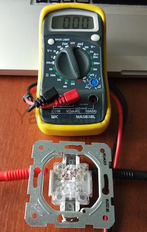
We ring the switch. When the switch is on, there should be a sound signal, when off, there should be silence and “1” on the indicator.
- Make sure there is voltage at the input and output of the machine. If it is, you can proceed to further verification.
- Prepare the device for operation and check its serviceability by short-circuiting the measuring leads.
- Unscrew the lamp from the socket.
- Touch one of the measuring probes to the base (the metal part of the lamp with threads), and the second to the central contact of the lamp (the insulated center of the end part of the base).
- A sound signal and instrument readings that are different from 0 or 1 mean that the lamp is working. If it is faulty, you need to replace it, which will solve the problem.
- We check the cartridge for serviceability. To do this, you need to disassemble the lamp, make sure the integrity of the connected wires and contacts. If everything is in order, then the cause of the failure is not in the cartridge. If malfunctions are detected, they must be eliminated. The lamp cannot be screwed in yet.
- We check the serviceability of the room switch. To do this, remove the plastic cover, unscrew the screws and take it out of the mounting box. We inspect the equipment for the appearance of carbon deposits and check the tightness of the fasteners. If everything is in order, you need to install the measuring ends of the tester on the contacts of the switch. The appearance of a sound signal when dialing in the on position will indicate that the equipment is working properly. The wires do not need to be disconnected.
During such a check, as a rule, a malfunction is identified, which becomes the cause of all the troubles. Eliminating it allows you to quickly solve the problem.
If the machine worked
To ensure electrical safety during work, in this case the voltage is turned off using a general apartment circuit breaker. Next, the serviceability of the socket and the wires connected to the lamp is determined according to the algorithm described above. If there are no faults, you need to check the wiring itself using a multimeter and the continuity function. Such malfunctions happen quite rarely, but they still happen, for example, when installing suspended ceilings or decorative interior elements.
The wiring in this case is performed as follows.
- Using a screwdriver, disconnect the connected conductor (if installed correctly, it is located at the bottom) and move it to the side. The “zero” of this group is, as a rule, located at the zero clamp under the machines.
- Unscrew the incandescent lamp from the socket. Using a ready-to-use tester, we check the line by connecting one of the measuring probes to “zero” and the other to the disconnected conductor. If the device beeps, it means the wiring is shorted.
- In this case, in the room under the ceiling above the switch, we find and open the junction box. We disconnect the wires.
- We check all groups of wires for short circuits.
To determine the section of the circuit in which there is a short circuit, we again check the circuits on the apartment panel with a multimeter. If the signal sounds, it means that it is the wire laid from the switchboard to the box in the room that needs to be repaired. Otherwise, the search will need to be continued until a result is obtained.
Video
From all of the above, we can conclude that having a multimeter with a dialing function in the house is an objective necessity for any home craftsman. With such a device, in most cases it will be possible to quickly eliminate minor faults without turning to specialists for help.
In everyday life, sometimes unforeseen situations arise when an appliance or kitchen equipment simply stops functioning. Of course, there are actually plenty of reasons. But if the equipment is working properly, then the problem is in the wiring.
The TransEnergoInvest company sells a wide range of power cables AABl, APVBbShp, AVBbShv, ASB, ASBl, AVVG, APVBbShv, APVPUG in Moscow and all regions of the Russian Federation, more details on the website t-e-i.ru
At t-e-i.ru you can purchase cables of any cross-section and in any quantities. You can be absolutely sure of quality, since this company has been present on the Russian market for more than five years. No matter how hard you try, it will be impossible to hide negative reviews over such a period of time.
Today there are a lot of techniques that use not only a multimeter, but also an ordinary incandescent lamp. With the help of a multimeter, these tasks can be completed faster.
To check you will need to perform the following sequence of actions:
- set the multimeter mode to test resistance;
- use a probe to check each wire strand one by one;
- correctly classify multimeter readings.
Everything is probably clear with the first two points. The latter requires some clarification. If the resistance is around 2 ohms, then the wire is absolutely intact (intact). Exceeding the 10 ohm mark is an alarming sign. There is probably a partial break in the line.
It should be noted that this method can be applied to wires of any kind and purpose (computer, power, telephone, etc.).

Perhaps the wire burned out in the wall and as a result, power supply to the apartment became impossible. Naturally, there is no direct access to the wire. And hammering a wall because of one wire is, to put it mildly, not an option.
In this case, a special device will help. In construction markets it is known under the label E-121. Electricians simply call him “Woodpecker”.
Point it at the location of the suspected cable break. The fact is that in this place, when power is applied, electromagnetic anomalies and turbulence will form. The device detects them at once and signals a break.
You can detect a break using the old “old-fashioned” method. However, this requires an ordinary radio receiver. You need to set it to a frequency of 100 kHz. The noise will increase where the break is located.
The video will demonstrate the process of testing the wire to find a break:
To repair home electrical wiring or a car's on-board network, you always need to know how to test wires with a multimeter. This device tests the integrity and serviceability of the cable; it can be used to check the insulation resistance and current voltage in the home electrical network. This is an indispensable meter for wiring and practical implementation of electrical projects.
Setting up and preparing the multimeter
To use the multimeter correctly, you need to configure it. This means that you need to select the value to be measured and the limit of its operation, that is, the value beyond which it will not go.
Symbols on the front panel of the meter
 A multimeter can be used to check various electrical quantities: current, voltage, resistance, frequency. It is also used to test the performance of various radio elements: resistors, capacitors, diodes and transistors. The very part of the word “multiple” implies the presence of several types of measurements. To select these types, there is a knob on the front panel of the tester, by turning which you can select the required value.
There is a higher class type of multimeter, for example, Agilent, in which the selection of measurement values is made not with a rotary knob, but with buttons. To select a value, simply click on the button corresponding to this value.
In most cases, the symbols depicted on the body of the multimeter represent designations of electrical quantities accepted in physics or conventional graphic designations of radioelements intended for testing . On the front panel you can find the following symbols:
- U - voltage symbol;
- V - stands for volts, this is also a measure of voltage;
- I is the current, when you set the knob to this designation the current strength will be measured;
- A - amperes, a measure of current;
- Ω, R - symbol of resistance;
- Ohm - measure of resistance, Ohms;
- -| |- - this icon indicates a capacitor, the multimeter will measure its capacitance;
- Diodes and transistors are also marked on the tester body with their symbols.
 But not only the measured values are indicated on the front panel of the tester: the holes for connecting the probes also have their own designations. One of the meter slots will always be occupied by the black probe. This is a common hole, it is usually marked with the inscription COM, which means “common”. In addition to it, the multimeter has two or three working holes, designed respectively for measuring voltage, low current and high current.
The socket marked U, Ω, Hz is intended for measuring resistance, voltage and frequency, as well as for testing various radio elements. You also need to install a probe here to test wires and cables for breaks.
The hole marked mA (mA) is used to test low currents (up to 1 ampere), and the hole marked A (10 A) is needed to measure high amperages.
Also next to the voltage and current icons there are symbols ~ or -. This indicates the nature of the measured quantity: direct or alternating current or voltage.
Limits of measured values
 In addition to designations of the values of the parameters being tested, designations of measurement limits are printed on the front panel of the multimeter. In more advanced equipment, these inscriptions are not present, since the tester electronics itself selects the limit based on the signal supplied to it at the input. However, most multimeters require manual adjustment of measurement limits.
Typically, limits are given by numbers that are multiples of 2: 2, 20, 200... Thus, when choosing a limit, you should be guided by the rule: choose a limit higher than the one being measured, but of the same order. For example, to measure the voltage in a home electrical network (in an outlet), you need to select the AC voltage measurement mode and the measurement limit of 2000 volts. And to test the wires with a multimeter, you need to select the resistance mode and the minimum measurement limit of 2 ohms. However, long cables require a higher measurement limit of 20 ohms. Additionally, you can turn on the button with a sound signal that sounds when a short circuit occurs (circuit presence).
Connecting the tester
To check the parameters of electrical circuits and the continuity of wires and cables with a multimeter, you must correctly connect the meter to the circuit being tested. When checking for circuit integrity, the required area between the meter leads is checked. Therefore, the tester is connected to the terminals of the circuit. If voltage is being measured, the multimeter must be connected in parallel to the section where the voltage is being tested.
When measuring current, the multimeter must be connected in series to the open circuit of the circuit being tested, for example, between the power supply terminal and the load terminal.
Checking electrical circuit parameters
When testing electrical circuits, you can test many of their parameters. This includes current, network voltage, and signal frequency. But to determine serviceability, you only need to ring the circuit for integrity and check the insulation resistance. Both can be done with a multimeter.
In order to know how to test electrical wiring with a multimeter, you need to correctly configure the measuring device and correctly perform the measurement steps. To check the integrity of the wire you need:

In the same way, wires in a car and cables of various electronic devices are tested.
In addition to checking integrity, wires are tested for insulation resistance. This can also be done with a multimeter:
- The probes remain in the same holes as when checking integrity;
- The measurement mode selected is the same - resistance test;
- The measurement limit must be selected as large as 20 or 200 megaohms;
- Touch the probes to opposite conductors of the cable: phase and neutral or phase and screen. In a car, this is ground and signal wire;
- The screen should remain displaying infinity; if there is any value instead, it means there is a short circuit somewhere. Changing values indicate interference in the network.

In addition to ordinary wires, there are high-voltage wires that can withstand high current and voltage loads. These include spark plug wires in cars. The current that is required when starting the engine flows through them; this current reaches 80-150 amperes. Knowing how to test high-voltage wires with a multimeter is required when diagnosing car electronics. The ringing of these wires occurs according to the specified scheme, with the difference that it is necessary to set a larger resistance measurement limit. Typically this limit should be set at 20 kilo-ohms.
After this, you need to find the ends of the wire and connect the multimeter probes to them. The resistance of this wire will be displayed on the device screen. It should be in the range from 1 to 10 kOhm.
In trucks, as well as in networks located in places subject to constant mechanical stress, conductors with a screen - armor or armored wires - are placed. The only special feature of the armored wire is the screen, made of durable metal. You can check the integrity and insulation of the armored wire in the same way as a regular one, you only need to have access to its ends and the screen outlet.
Safety requirements
When performing any inspections of live electrical networks, safety requirements must be followed. You cannot work without protective insulated shoes, and it is also better to wear rubber gloves. When checking the integrity and insulation resistance of electrical circuits, it is necessary to de-energize the network by turning off the circuit breakers, so all checks should be carried out during daylight hours, since with emergency lighting and the light of lanterns you can only work in case of an emergency.
The wiring in your home is the most important part of your electrical network, but sometimes this network fails. Determining exactly where the break occurred is sometimes difficult. The task is especially difficult in the case of hidden wiring, where it is simply impossible to do without network testing. How to ring the wires, checking the integrity of the network?
How to ring the wiring in an apartment: where to start
Undoubtedly, if you want to check whether the electricity in your home is working properly, it is better to turn to specialists. However, sometimes it is still more convenient to conduct at least a superficial check on your own. Sometimes you have to wait a long time for an electrician, and checking the wires is quite a simple operation in this area.

So, in what cases should you look for a broken wiring by calling it:
- Testing new wiring in the house;
- Repair of an existing network or its individual components.
If you want to check completely new wiring with your own hands, then the diagnostics will rely on finding errors either by builders or electricians. We immediately check the wiring for a short circuit - this is easy to do, ideally there should be no contact between zero, phase and ground. In general, here the quality of insulation directly depends on the quality of the cable and if something is wrong, prepare to replace it.
The second stage of inspection is visual, which means that you can visually detect any mechanical damage caused by builders. If there are any, then, of course, the wiring should under no circumstances be hidden under a layer of finishing, since it is all sorts of suspicious places that usually turn into breaks. After the initial check, if everything looks okay, you can start ringing the wires, thanks to which you can identify breaks that are not noticeable to the eye.
How to ring wires at home
To test the electrical network, you only need one device - a multimeter. A home test for a short circuit between the zero point, phase and ground can be done without a multimeter, but the name of all electricians already requires the presence of this device. The cost of the multimeter is very affordable, and the device is universal - it works as a tester of voltage strength, resistance and network integrity.
In order to start dialing, you must switch the device to the appropriate mode. This will allow:
- Check the integrity of the contacts;
- Identify breaks in the electrical network;
- Check the operation of the socket or switch;
- Determine which cable is connected where.

The trivial situation when you have a bunch of cables and have no idea which one is connected where can be solved thanks to a multimeter. The same applies to situations where there is a socket or switch, an active conductor, etc.
Checking electrical wiring with a multimeter
To start checking, put the device in ringing mode, usually it is marked with a bright LED. Next, we move to the distribution box - it is best to make the call here. Usually in the box of new houses you can see a lot of wires without any marks. We turn on the machine and check all the wires with an indicator screwdriver - we find the phase and mark it.
You can make marks on the wires with a marker, but it is more reliable, for years, to wrap the wires with electrical tape.
Next, you need to find zero - to do this, put the device in voltage measurement mode and touch the phase with a screwdriver to the device and at the same time look for the desired wire with a voltage of 220 volts. In general, do not be surprised if some wires have a voltage of 200 V, and others 400-600 V. Having checked all the wires and made their markings, we make sure that all the wiring in the box is without breaks.
How to test a wire for break and other conductors with a multimeter
In order to check a specific wire for breaks, you must first disconnect the conductor from the current source, and then switch the multimeter either to the continuity mode or to the resistance measurement mode in the network, but with the roughest parameters. Next, we proceed to check the conductor - the whole one will show zero resistance, but deviations from zero will indicate the presence of breaks.
If you want to check the diode for breaks, then the scheme of action will be slightly different - the resistance in one direction in the normal state is close to zero, and in the other direction it will be extremely high. Remember that the diode should be tested in both directions, and if it is corrected, it should only pass current in one of them.

When checking an LED, everything is even more confusing - the voltage at the contacts can be very low, and the resistance can be close to infinity, and this is quite normal. The LED works in such a way that it transmits diodes only in a certain voltage range. If the polarity is correct and checked with an expensive and sensitive multimeter, the diode will glow very dimly, but in most models the sensitivity will not allow any reaction to be detected at all and the diode will remain extinguished.
If the LED must be tested properly, then connect it to a current source with a rated voltage, but a minimum current level. The only exception is non-soldered diodes; they can be checked with any multimeter by switching it to transistor testing mode.
And lastly, how to ring a transformer? This task does not cause difficulties for electricians; the integrity of both windings can be established, however, as for interturn short circuits, they cannot be verified at all with standard equipment. So, as for the first, we check as follows - we select a fuse and turn on the transformer through a fuse selected with the rated voltage into the outlet. If the fuse burns, then everything is clear - there is a short circuit in one of the turns of the transformer; if it does not burn out but gets very hot, then this also indicates a short circuit, but on a smaller scale, for example in one or two turns.
In general, it is quite possible to ring the wiring in a house with your own hands, but the task requires at least basic knowledge in the field of electrical engineering. Wiring testing is mainly required either when accepting new housing with fresh wiring, or when repairing an existing one. Wire testing is carried out using a multimeter, a device that can be useful in everyday life, as it can check the integrity of the wires, the voltage strength, and the resistance in the network. Using a multimeter, you can check the wires, transformer, diode and LED, but in each individual case some nuances of the settings should be observed.
Often at home it is necessary to discover the reason why one of the electrical networks is not working. For example, the lamp in the room does not light up. There are several reasons for this: the light bulb in the lamp burned out, the contacts in the socket or switch burned out, the electrical wiring turned out to be broken. The most unpleasant reason is the last one. But how can you determine that there is a break in the wiring? There is only one option - to ring the electrical supply wire, for which you can use a multimeter. Of course, there are other options besides this device, but this one is the most reliable. So, how to test wires with a multimeter is the solution to the problem.
Let's start with the fact that using a multimeter you can test wiring for the value of indicators such as current and voltage. In this case, the wires must be live. A test to determine the presence of a break is a determination of the resistance value of the conductor, that is, whether it is present or absent. So, if the multimeter shows “0” on the display, it means that the wires are intact and there is no break in them. If resistance is shown on the display, this indicates that there is a break. Basically, it's as simple as that. The only thing you need to pay attention to is that when testing the wiring for resistance, there should be no voltage in it.
First of all, you need to set up the device in ohmmeter mode. To help you understand how to do this correctly, look at the photo below, where arrows indicate all positions. But we are interested in the “Dialing” position; this is where the device handle should be placed.

Now you need to check the tester itself. To do this, connect two probes (red and black), the display should show “zero” or a reading slightly higher than it. This indicates that the device is working correctly.
Since our task is determined by the question of how to ring the wire, we are confident that there are no other electrical elements installed in the wiring that can accumulate electrical potential. That is, we have a linear conductor made of either copper or aluminum.
Continuity of wires
The mode of testing wires with a multimeter is that you need to connect the probes of the device to the two ends of the wire and determine whether there is resistance in the wire. By the way, many (modern) testers have alarm functions. That is, you conduct testing, and the presence of resistance is confirmed by the squeak of the device. Very comfortably.
But there's a catch. It’s good if you check a wire that will only be used in electrical wiring installation. There will be no problems with connecting the probes, because the length of the wires of the probes themselves is quite short. But how to ring wires that are already laid, for example, old electrical wiring is checked.
Let's look at this using an example, the same lamp. So, two wires are connected to it: phase and zero. To test, you will need to disconnect the connection of the wires to the light source and twist the ends of the two lines together. That is, you will need to short-circuit the line and make a ring out of it. But keep in mind that before this you will need to disconnect both wires from the supply circuits in the distribution box. Now, right there in the junction box, you need to connect the probes to two wires and test with a multimeter.
And if the device shows a break, then your task is to repair the electrical wiring or install a new one. If you decide to make repairs, you need to determine the location of the break. To do this, you will need to use special devices. For example, a domestic specimen called “Woodpecker”. First, you will need to apply voltage to the wiring, and only then determine the location of the wire break.
This method of checking wires is also suitable for car enthusiasts. Often the ignition system fails only because the high-voltage wires in it do not work. Of course, the reason may not be in them, but this problem is present. Here everything is done exactly the same as described above. The only thing is the indicators on the multimeter screen. So, if the device on the display shows numbers from 3.5 to 10 kOhm (the limits will first need to be set on the device itself), then such wires are considered intact. If the resistance value exceeds 10 kOhm, then there is a break in the wires; you will have to replace them with new ones. However, it is necessary to make a reservation that the specified range is not standard, everything will depend on the make of the car. But as practice shows, the spread of permissible values can be 2-4 kOhm.

In principle, all types of cables are tested according to the same principle. Even a generator based on copper wire is checked for breaks in the same way. We will not mention checking the armored wire or other types of power cables.
Conclusion on the topic
Our task is simple, to understand the question of how to check a cable with a multimeter for a break? Let's face it, this is the most reliable method, which uses the most versatile device. If you understand it, then at home it will not be difficult to determine whether there was a wire break or not.