Quickly check your NTV Plus balance by number. Personal account NTV plus
Being far outside the city, where you rarely see a house with satellite dish, and there is no way to connect cable TV, sometimes you wonder how to make an antenna for a TV with your own hands.
Indeed, anything can happen to an old antenna. The cable is damaged, the signal is lost, the wire comes loose and you are left without television. The situation is unpleasant, but, as it turns out, it is quite fixable. This problem can be solved if you manage to build an indoor antenna using improvised materials and, perhaps, without even resorting to a soldering iron.
The easiest way to make a TV antenna
Living in an apartment building, we are not immune to problems with the possible lack of TV broadcast. But the problem can be solved quickly and quite effectively. To do this, we need copper wire and a knife. Using a knife, we strip both ends of the wire and tie one of them to the heating battery, and insert the other into the socket of your TV.

We turn it on and check the signal. The central heating radiator extends to the roof, thereby increasing the signal, so we, of course, cannot guarantee a hundred channels, but such an antenna will pick up 5-7 and provide a fairly high-quality display.
TV antenna made from aluminum cans
An ignorant person is unlikely to realize that indoor antenna with your own hands can be made from ordinary beer cans or Coca-Cola cans. Moreover, this method has been known for a very long time. For this we will need the following items:
1. Two aluminum cans.
2. Brass, copper wire or old tv cable.
3. Triangular clothes hanger.
4. Soldering iron (for structural strength and signal improvement, but you can do without it).
5. Knife.
6. Electrical tape, scotch tape.
Manufacturing process of a can antenna
We rinse the jars and dry them thoroughly. Then we fix the hangers on the edges so that they fit against the bottom side. It is best to secure the cans using adhesive tape or electrical tape, but you can also use other available means. The banks need to hold up well.
Then, we strip the ends of the wire or cable on both sides and thread their ends through the ears, with the help of which the cans are opened. We press these ears to the lid of the jar and insert the other end of the cable into the connector.
Note!
For structural strength, the wire can be soldered to the can and these places can be insulated.
To increase the number of channels, you need to use jars of larger diameter.
TV Antenna UHF and VHF
If you have some skills in working with a soldering iron, then you can easily assemble an antenna for a TV with your own hands for the decimeter and meter ranges. The design does not require engineering skills and to create it we will need: 1. A copper wire 80 cm long and up to 3 mm in diameter. 2. Double-sided fiberglass. 3. Coaxial cable up to 2 meters long and with a resistance of 75 Ohms. 4. Plug.

The procedure for manufacturing a decimeter antenna
First, you need to find a copper wire with a diameter of 2-3 mm. A single-core cable used when installing electrical wiring is most suitable for this. If you find a stranded wire, you need to separate one core without damaging the insulation. As a last resort, you can use aluminum wire. If there is no insulation on the wiring, then for aesthetics, it can be put into a tube, for example, made of vinyl chloride. Then, make a circle with a diameter of 22 cm from the wire. For the convenience of making such a circle, you can use any container of a similar diameter.
Board assembly
To continue assembling such an antenna for television, you will have to make the board yourself. There is nothing complicated about this. We take a piece of PCB measuring 2.5*3.5 cm and a thickness of 1.5 mm, and place copper wire tracks on its surface, also as indicated in the diagram.

Board assembly diagram
The wire diameter should be within 0.4 mm. It can be attached to the board using glue. To reduce external influences and give our design beautiful view, we hide our board in a box made of plastic or metal, having previously drilled holes for the ring and cable. After these preparatory work, we begin to assemble the structure.
Assembling the TV antenna structure
We tin the ring ends with solder and put them into our box with the board. Then we bend them at a right angle, bring them to the board and seal them. After this, we turn the board to face the bottom of the box and begin preparing the cable. To do this, install a plug on one end of the cable, and disconnect the other and solder it to the board on the reverse side. We fix one of the ends, the central core, to the right end of the ring, and solder the second to the board of our product. After these manipulations, the design is ready. We insert the plug into the TV socket and configure the channels.
DIY TV antenna for digital television
If you know how to hold a soldering iron and a screwdriver in your hands, you can make an antenna for digital television at home, which will be of better quality than many Chinese analogues that have flooded our market and, most importantly, almost free of charge. For this we will need the following items: 1. A board 7 cm wide and 55 cm long. 2. Copper wire, 39 cm long and the diameter of the central core is 4 mm. 3. Self-tapping screws in the amount of 10 pcs. 4. Pencil, ruler, knife. 5. Plug.
First, take a board of the required size and make markings according to the diagram:

Construction order
Dimensions are in inches. To convert to centimeters, multiply by 2.5 and round to the nearest tenth. For example, 2 and 5/8″, when multiplied we get 6.56, rounded to 6.6 cm. Then we cut our wire into 8 parts and get pieces of 37.5 cm. On each piece we make cuts 2 cm long, for connections, and clean them. After this, we cut two more wires of 22 cm each and strip them in the places where connections will be made. We bend the wires, which we previously cut into 37.5 cm, into a V shape so that the distance between the edges is 7.5 cm.
The final stage of antenna assembly
Now, so that we can get a real one TV antenna for digital television, you need to complete the assembly correctly. To do this, we need to buy a plug with a coil inside and begin the process of connecting the coil to the cable. The cable is connected to the coil through the lower contacts. After this, we complete the antenna assembly by screwing two wires, 22 cm long, to the central screws. On the other hand, we attach these wires to a plug with a coil, which, in turn, must first be attached to back side planks. That's it, the reel is ready for use.
Frame wave channel
To make such an antenna, take copper wire and bend a frame from it. The side of the frame should be about 10 cm. At the junction of the ends, we tie them using the “pigtail” method. After this, after 2 cm, we begin to twist the same frame, connecting the ends in a similar way.
In contact with
See inaccuracies, incomplete or incorrect information? Do you know how to make an article better?
Would you like to suggest photos on the topic for publication?
Please help us make the site better! Leave a message and your contacts in the comments - we will contact you and together we will make the publication better!
High-quality antennas have always been difficult to obtain - the Soviet industry practically did not produce them, so people made them themselves from improvised materials. Today the situation has practically not changed - in stores you can only find lightweight aluminum Chinese crafts that do not show good results and rarely live more than a year. What to do if you like to watch TV, but there is no quality reception? The answer is simple -Given free time and a pair of skillful hands, anyone can handle this.
Quite recently in Russia there was analog television, but now almost the entire country has switched to digital broadcasting. Its main difference is that it operates in the decimeter range.
You can create a homemade antenna for the digital range at home
This was done for reasons of economy and safety - maintenance of transmitting antenna-feeder stations is virtually not required, their maintenance is reduced to a minimum, and the harm from contact with powerful transmitters for masters is minimal. But such stations have one serious drawback - low power. And if in a big city the signal can often be caught even for a segment copper wire, reception may be difficult away from the transmitter. If you live outside the city, in remote areas or villages, you will have to assemble your own antenna and take it outside to catch the desired signal.
Attention:Signal problems can occur even in the city center. Decimeter waves are practically not dampened by other sources, but are reflected from thick reinforced concrete walls. In modern high-rise buildings there are many places where they are completely attenuated before reaching the TV receiver.
It is also worth noting that DVB-T2 (the new television standard) offers a fairly constant, but weak signal. When the noise level is one and a half to two units higher than normal, the TV reproduces the broadcast quite clearly, but as soon as the noise exceeds 2 dB, the signal disappears completely. Digital television not sensitive to electromagnetic interference - it is not knocked down by a running refrigerator or microwave. But if a mismatch occurs anywhere in the system, the picture stops or falls apart. High qualitywill solve this problem, but in some cases it will have to be taken outside or onto the roof.
Basic requirements for antennas
The current television standards in the USSR do not fit modern realities - the protective and directional coefficients today have practically no effect on the signals. The airwaves in cities are clogged and contain a lot of dirt, so you shouldn’t pay attention to these coefficients. You are guaranteed to get interference on any antennas, so there is no need to reduce the efficiency factor and efficiency factor. It is better to improve the antenna gain so that it receives a wide range of airwaves and selects the desired stream, rather than focusing on a specific signal. The processor of the set-top box or TV itself will isolate the necessary signals and create a normal picture.
 Classic Polish antenna with amplifier
 So, Experienced engineers recommend building band antennas. They must be correctly timed when receiving signals in the classic way, and not through engineering “optimizations” and traps. The ideal option is that the device fully complies with theoretical calculations and geometry. Also, the constructed antenna must be consistent with the cable at operating ranges without the use of matching devices. In this case, it is best to create a frequency response that is smooth and even, since when the amplitude-frequency response dips or jumps, phase distortions appear.
Attention: analog Antennas with ferrite USS, which provide full reception of the old signal, practically do not work with DVB. You need to build a “digital” antenna.
In the article we will analyze modern types of antennas that work with new digital broadcasting.
Antenna types
DIY antennas for digital TV Can you assemble it at home? There are three most common options:
- All-wave, or as radio amateurs call it, frequency-independent. It is assembled very quickly and does not require high knowledge or specialized tools. Well suited for the private sector, villages, dacha cooperatives - where the airwaves are not clogged with garbage, but not too far from the transmitter.
- Log-periodic range. It has a simple design and receives the signal well at close and medium distances from the transmitter. Can be used as a remote antenna if the transmitter is located far away, or as a home wall antenna.
- Z-antenna and its variations. Many radio amateurs are familiar with meter-long “zeshki” - they are quite large and require a lot of effort to assemble. But in the decimeter range they are quite compact and do their job well.
Nuances of construction
If you want to build a quality antenna, you must master the art of soldering. You cannot twist the contacts and guides - during operation they oxidize, the signal is lost, and the picture quality deteriorates. Therefore, all connections are soldered.
 Such connections are unacceptable - be sure to solder them
 You also need to deal with points of zero potential, where currents arise even in the absence of voltage. Experts recommend making them from a single piece of metal, without using welding at all. Even well-welded pieces can make noise at the boundary values, while a solid strip will “pull out” the signal.
Also when creating homemade antenna for digital TV you need to figure out how to solder cables. Today, copper is practically not used for braiding, since it is expensive and quickly oxidizes. Modern braiding is made of steel, which is not afraid of corrosion, but it is very difficult to solder. It should not be overheated or squeezed. For connections, use 36-40 watt soldering irons, flux and light solders. Dip the winding well into the flux and apply solder - it takes up perfectly with this method of application.
All-wave antenna
The all-wave antenna has a fairly simple design. It consists of triangles, copper wire and wooden slats. You can study the design in more detail in the picture - it does not represent anything supernatural.
The thickness of the wire can be any, the distance between adjacent wires is 25-30 mm, the distance between the plates is no more than 10 mm. The design can be improved by eliminating plates and using PCB. It needs to be given the appropriate shape or simply remove the copper foil in the shape of a triangle.
The remaining proportions are standard - the height of the device must match the width, the plates diverge at right angles. Zero potential is on the extreme line home antenna for tv , just at the intersection of the cable with the vertical guide. To avoid loss of quality, the cable must be tied to it with a tie - this is enough for coordination. Such an antenna, hung outside or directed at a window, receives virtually the entire frequency range, but has a slight dip, so you need to set the correct angle when fixing the antenna.
By the way, this design can be modernized using ordinary aluminum beer and cola cans. The principle of its operation is as follows: as the shoulder span increases, the working band expands, although other indicators remain within the original limits. The Nadenenko dipole, often used in military developments, works on the same principle. Aluminum cans are ideal in shape and size, creating vibrator arms in the decimeter range.
 Two-can antenna for TV
 You can create a simple can antenna by simply soldering two cans to a cable. This DIY indoor TV antenna Suitable for viewing channels at a short to medium distance from transmitters. There is no need to coordinate anything in this scheme, especially if the cable length is less than 2 meters.
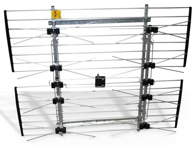
You can complicate the design by assembling a full-fledged array from eight cans and using an amplifier from a regular Polish antenna. This design is perfect for hanging outdoors in areas remote from the transmitter. To enhance the signal, a metal mesh can be placed at the back of the structure.
Z antenna
Complex Z-antenna designs with multiple loops exist, but in most cases they are not needed. You can easily assemble a structure from ordinary copper wire 3 mm thick. If you don’t have one, then just buy a 3 mm single-core copper wire 120 mm long - this will be enough for your work. This design consists of two segments. We bend the wire according to this pattern:
- The starting section is 14 centimeters long. Its edge is bent into a loop to connect with the last one (the loop is 1 cm, the total length of the first piece is 13 cm).
- The second piece is bent at 90 degrees (it is better to bend it with pliers to maintain the angles). Its length is 14 cm.
- The third piece is bent at 90 degrees parallel to the first, length 14 cm.
- The fourth and fifth pieces are 13 cm each, the bend does not reach the loop by 2 cm.
- The sixth and seventh pieces are 14 cm each, bent at 90 degrees.
- Eighth - returns to the loop, length 14, 1 cm goes to a new loop.
Next, you need to thoroughly strip the two loops and solder them. The opposite corner is also cleaned. The cable contacts are soldered to them - one is central, the other is braided. There is no difference which contact to solder to.. It is advisable to insulate the soldered areas; for this you can use sealants or hot-melt adhesive. The ends of the cable are soldered to the plug and also insulated with cambric.
 You can assemble such an antenna in half an hour.
 To avoid displacement of segments, the edges can be strengthened. To do this, take a regular plastic cap from a five-liter bottle, cut 4 slits in it so that the wire is recessed to the base. Cut the fifth hole for the cable. Then place the antenna in the cover (after checking the quality and reliability of the soldering), and fill it with hot-melt adhesive. The resulting design will be practically eternal - it is capable of receiving a stable signal at a distance of up to 10 km from the source.
So you already know What can be used instead of an antenna for a TV. In fact, the structures are much larger than those we described, but even these will be quite enough for you. If you live far from the signal source, then you will need amplifying antennas - you can get by with a classic “polka” with amplification. Well, if everything is bad with the airwaves, then use satellites.
Despite the rapid development of the Internet, television remains the main source of information for the majority of the population. But in order for your TV to have a high-quality picture, you need good antenna. It is not at all necessary to buy a television antenna in a store, because you can make it yourself and save a lot of money.
How to do quality antennas for different broadcast bands and what materials to use, you can find out by reading our article.
There are many types and forms of television antennas, the main ones are listed below:
- Antennas for receiving a “wave channel”.
- Antennas receiving a “traveling wave”.
- Loop antennas.
- Zigzag antennas.
- Log-periodic antennas.
- Array antennas.


 Array antennas
 Antennas for digital television reception
The whole world, including our country, has switched from analogue to digital broadcasting. Therefore, when making an antenna with your own hands or buying it in a store, you need to know which antenna is best suited for receiving DVB-T2 format:

If you live not far from a TV tower, then you can easily make a simple antenna for receiving a signal in DVB-T2 format with your own hands:
- Measure 15 centimeters of the antenna cable from the connector.
- Remove 13 centimeters of outer insulation and braid from the cut edge, leaving only the copper rod.
- Referring to the TV picture, point the rod in the desired direction.
The antenna is ready! It should be noted that such a primitive antenna is not capable of providing a high-quality and stable signal at a distance from the TV tower and in places with sources of interference.
DIY antennas
Let's look at several options for television antennas that you can make yourself from scrap materials:
Beer can antenna
An antenna from beer cans can be made in literally half an hour, using the materials you have on hand. Of course, such an antenna will not provide a super-stable signal, but for temporary use in a country house or in a rented apartment it is quite suitable.  Beer can antenna
To make an antenna you will need:
- Two aluminum cans of beer or other drink.
- Five meters of television cable.
- Plug.
- Two screws.
- A wooden or plastic base on which the jars will be attached (many people use a wooden hanger or mop).
- Knife, pliers, screwdriver, insulating tape.
After making sure that you have all the above items in stock, do the following:
- Strip one end of the cable and attach the plug to it.
- Take the other end of the cable and remove 10 centimeters of insulation from it.
- Unravel the braid and twist it into a cord.
- Remove the plastic layer from the insulating rod of the cable to a distance of one centimeter.
- Take the jars and screw the screws into them in the center of the bottom or lid.
- Attach a rod to one can and a braided cable cord to the other, screwing them onto screws.
- Attach the jars to the base using electrical tape.
- Attach the cable to the base.
- Insert the plug into the TV.
- Moving around the room, determine the place best welcome signal and attach the antenna there.
There are other variations of this antenna, with four and even eight banks, but no obvious effect of the number of banks on the signal quality has been identified.
You can also learn how to make an antenna from beer cans from the video:
Kharchenko zigzag antenna
The antenna received its name in 1961, after the name of its inventor Kharchenko K.P., who proposed using zigzag-shaped antennas to receive television broadcasts. This antenna is very well suited for receiving digital signals.  Antenna Kharchenko
To make a zigzag antenna you will need:
- Copper wire with a diameter of 3-5 mm.
- TV cable 3-5 meters.
- Solder.
- Soldering iron.
- Plug.
- Insulating tape.
- A piece of plastic or plywood for the base.
- Fastening bolts.
First you need to make an antenna frame. To do this, take the wire and cut off a piece of 109 centimeters. Next, we bend the wire so that we get a frame of two parallel rhombuses, each side of the rhombus should be 13.5 centimeters, make loops from the remaining centimeter to fasten the wire. Using a soldering iron and solder, connect the ends of the wire and close the frame.
Take the cable and strip its end so that you can solder the rod and cable shield to the frame. Next, solder the rod and cable shield in the center of the frame. Please note that the screen and the rod should not touch.
Place the frame on the base. The distance between the corners of the frame at the junction with the cable should be two centimeters. Make the size of the base approximately 10 by 10 centimeters.
Strip the other end of the cable and install the plug.
If necessary, attach the antenna base to a stand for further installation on the roof.
More detailed instructions on the manufacture of the Kharchenko antenna, you can watch in the video:
Coaxial cable antenna
To make the antenna you will need a 75 ohm coaxial cable with a standard connector. To calculate the cable length required for the antenna, you need to find out the digital broadcasting frequency and divide it in megahertz by 7500, and round the resulting amount.  Cable antenna
Once you have the cable length, do the following:
- Strip the cable on one side and insert it into the antenna connector.
- Step back two centimeters from the edge of the connector and make a mark from which you will measure the length of the antenna.
- Having measured the desired length, bite off the excess with pliers.
- In the area of the mark, remove the insulation and braiding of the cable, leaving only the inner insulation.
- Bend the cleaned part at an angle of 90 degrees.
- Set up your TV with a new antenna.
You can visually consolidate the information by watching the video:
Satellite antenna
It’s worth mentioning right away that to receive a satellite signal you need a tuner and a special set-top box. Therefore, if you do not have this equipment, then creating a satellite dish with your own hands will not be possible, since you yourself can only make a parabolic reflector:

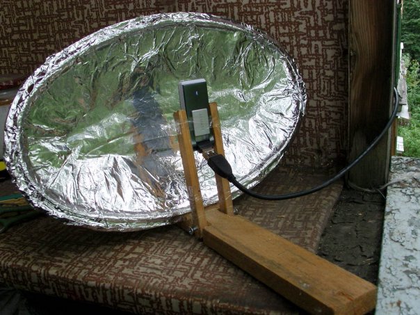
All of the methods listed above can be considered seriously only out of sporting interest, since making a parabolic reflector by hand is a very labor-intensive and expensive process. In addition, it is very difficult to accurately calculate the parameters of a satellite dish at home. Therefore, we advise you not to be original and buy satellite dish in full set.
Antenna amplifier
If the place where you live is weak television signal and a regular antenna cannot provide a high-quality picture on your TV, then an antenna amplifier can help in this situation. You can make it yourself if you have a little knowledge of radio electronics and know how to solder. 
Amplifiers should be installed as close to the antenna as possible. Nutrition antenna amplifier It is better to carry it out via a coaxial cable through an isolation.  Isolation power circuit
The decoupler is installed at the bottom of the TV and is supplied with 12 volt power from the adapter. Two-stage amplifiers consume a current of no more than 50 milliamps; for this reason, the power of the power supply should not exceed 10 watts.
All connections of the antenna amplifier on the mast must be made by soldering, since the installation of mechanical connections will lead to their corrosion and rupture during further operation in an aggressive external environment.
There are times when you have to receive and amplify a weak signal in the presence of powerful signals from other sources. In this case, both weak and weak signals enter the amplifier input. strong signals. This leads to blocking the operation of the amplifier or switching it to a non-linear mode, mixing both signals, which is expressed in the overlay of the image from one channel to another. Reducing the amplifier supply voltage will help correct the situation.
Please note that UHF amplifiers are greatly influenced by signals in the meter range. To reduce the impact of meter signals, a high-pass filter is placed in front of the UHF amplifier, which blocks meter waves and transmits signals only UHF.
Below is a diagram of a VHF antenna amplifier:

We also suggest that you familiarize yourself with the circuit of the decimeter amplifier:

You can see the operating principle of the antenna amplifier in the video:
Now, having familiarized yourself with the diagrams and armed with a soldering iron, you can safely begin making an antenna amplifier.
We hope that our article about television antennas was useful to you!
Once upon a time, a good television antenna was in short supply; purchased ones did not differ in quality and durability, to put it mildly. Making an antenna for a “box” or “coffin” (an old tube TV) with your own hands was considered a sign of skill. Interest in homemade antennas continues to this day. There is nothing strange here: the conditions for TV reception have changed dramatically, and manufacturers, believing that there is and will not be anything significantly new in the theory of antennas, most often adapt electronics to long-known designs, without thinking about the fact that The main thing for any antenna is its interaction with the signal on the air.
What has changed on air?
Firstly, almost the entire volume of TV broadcasting is currently carried out in the UHF range. First of all, for economic reasons, it greatly simplifies and reduces the cost of the antenna-feeder system of transmitting stations, and, more importantly, the need for its regular maintenance by highly qualified specialists engaged in hard, harmful and dangerous work.
Second - TV transmitters now cover almost all more or less populated areas with their signal, and a developed communication network ensures the delivery of programs to the most remote corners. There, broadcasting in the habitable zone is provided by low-power, unattended transmitters.
Third, the conditions for the propagation of radio waves in cities have changed. On the UHF, industrial interference leaks in weakly, but reinforced concrete high-rise buildings are good mirrors for them, repeatedly reflecting the signal until it is completely attenuated in an area of seemingly reliable reception.
Fourth - There are a lot of TV programs on air now, dozens and hundreds. How diverse and meaningful this set is is another question, but counting on receiving 1-2-3 channels is now pointless.
Finally, digital broadcasting has developed. The DVB T2 signal is a special thing. Where it still exceeds the noise even just a little, by 1.5-2 dB, the reception is excellent, as if nothing had happened. But a little further or to the side - no, it’s cut off. “Digital” is almost insensitive to interference, but if there is a mismatch with the cable or phase distortion anywhere in the path, from the camera to the tuner, the picture can crumble into squares even with a strong clean signal.
Antenna requirements
In accordance with the new reception conditions, the basic requirements for TV antennas have also changed:
- Its parameters such as the directivity coefficient (DAC) and the protective action coefficient (PAC) are now of no decisive importance: modern air is very dirty, and along the tiny side lobe of the directional pattern (DP), at least some interference will get through, and You need to fight it using electronic means.
- In return, the antenna's own gain (GA) becomes especially important. An antenna that catches the air well, rather than looking at it through a small hole, will provide a reserve of power for the received signal, allowing the electronics to clear it of noise and interference.
- A modern television antenna, with rare exceptions, must be a range antenna, i.e. her electrical parameters should be preserved in a natural way, at the level of theory, and not squeezed into an acceptable framework through engineering tricks.
- The TV antenna must be coordinated with the cable over its entire operating frequency range without additional devices coordination and balancing (USS).
- The amplitude-frequency response of the antenna (AFC) should be as smooth as possible. Sharp surges and dips are certainly accompanied by phase distortions.
The last 3 points are due to admission requirements digital signals. Customized, i.e. Working theoretically at the same frequency, antennas can be “stretched” in frequency, for example. antennas of the “wave channel” type on the UHF with an acceptable signal-to-noise ratio capture channels 21-40. But their coordination with the feeder requires the use of USSs, which either strongly absorb the signal (ferrite) or spoil the phase response at the edges of the range (tuned). And such an antenna, which works perfectly on analogue, will receive “digital” poorly.
In this regard, from all the great variety of antennas, this article will consider TV antennas, available for self-production, of the following types:
- Frequency independent (all-wave)– does not have high parameters, but is very simple and cheap, it can be done in literally an hour. Outside the city, where the airwaves are cleaner, it will be able to receive digital or a fairly powerful analogue not a short distance from the television center.
- Range log-periodic. Figuratively speaking, it can be likened to a fishing trawl, which sorts the prey during fishing. It is also quite simple, fits perfectly with the feeder throughout its entire range, and does not change its parameters at all. The technical parameters are average, so it is more suitable for a summer residence, and in the city as a room.
- Several modifications of the zigzag antenna, or Z-antennas. In the MV range, this is a very solid design that requires considerable skill and time. But on the UHF, due to the principle of geometric similarity (see below), it is so simplified and shrunk that it can well be used as a highly efficient indoor antenna under almost any reception conditions.
Note: The Z-antenna, to use the previous analogy, is a frequent flyer that scoops up everything in the water. As the air became littered, it fell out of use, but with the development of digital TV, it was once again on the high horse - throughout its entire range, it is just as perfectly coordinated and keeps the parameters as a “speech therapist.”
Precise matching and balancing of almost all antennas described below is achieved by laying the cable through the so-called. zero potential point. It has special requirements, which will be discussed in more detail below.
About vibrator antennas
In the frequency band of one analog channel, up to several dozen digital ones can be transmitted. And, as already said, the digital works with an insignificant signal-to-noise ratio. Therefore, in places very remote from the television center, where the signal of one or two channels barely reaches, the good old wave channel (AVK, antenna wave channel), from the class, can be used for receiving digital TV vibrator antennas, so at the end we’ll devote a few lines to her.
About satellite reception
There is no point in making a satellite dish yourself. You still need to buy a head and a tuner, and behind the external simplicity of the mirror lies a parabolic surface of oblique incidence, which not every industrial enterprise can produce with the required accuracy. The only thing homemade people can do is set up a satellite dish, about that.
About antenna parameters
Accurate determination of the antenna parameters mentioned above requires knowledge of higher mathematics and electrodynamics, but it is necessary to understand their meaning when starting to manufacture an antenna. Therefore, we will give somewhat rough, but still clarifying definitions (see figure on the right):

- KU is the ratio of the signal power received by the antenna on the main (main) lobe of its DP to its same power received in the same place and at the same frequency by an omnidirectional, circular, DP antenna.
- KND is the ratio of the solid angle of the entire sphere to the solid angle of the opening of the main lobe of the DN, assuming that its cross section is a circle. If the main petal has different sizes in different planes, you need to compare the area of the sphere and its cross-sectional area of the main petal.
- SCR is the ratio of the signal power received at the main lobe to the sum of the interference powers at the same frequency received by all secondary (back and side) lobes.
Notes:
- If the antenna is a band antenna, the powers are calculated at the frequency of the useful signal.
- Since there are no completely omnidirectional antennas, a half-wave linear dipole oriented in the direction of the electric field vector (according to its polarization) is taken as such. Its QU is considered equal to 1. TV programs are transmitted with horizontal polarization.
It should be remembered that CG and KNI are not necessarily interrelated. There are antennas (for example, “spy” - single-wire traveling wave antenna, ABC) with high directivity, but single or lower gain. These look into the distance as if through a diopter sight. On the other hand, there are antennas, e.g. Z-antenna, which combines low directivity with significant gain.
About the intricacies of manufacturing
All antenna elements through which useful signal currents flow (specifically, in the descriptions of individual antennas) must be connected to each other by soldering or welding. In any prefabricated unit in the open air, the electrical contact will soon be broken, and the parameters of the antenna will deteriorate sharply, up to its complete unusability.
This is especially true for points of zero potential. In them, as experts say, there is a voltage node and a current antinode, i.e. his highest value. Current at zero voltage? Nothing surprising. Electrodynamics has moved as far from Ohm's law on direct current as the T-50 has gone from a kite.
Places with zero potential points for digital antennas are best made bent from solid metal. A small “creeping” current in welding when receiving the analogue in the picture will most likely not affect it. But, if a digital signal is received at the noise level, then the tuner may not see the signal due to the “creep”. Which, with pure current at the antinode, would give stable reception.
About cable soldering
The braid (and often the central core) of modern coaxial cables is made not of copper, but of corrosion-resistant and inexpensive alloys. They solder poorly and if you heat them for a long time, you can burn out the cable. Therefore, you need to solder the cables with a 40-W soldering iron, low-melting solder and with flux paste instead of rosin or alcohol rosin. There is no need to spare the paste; the solder immediately spreads along the veins of the braid only under a layer of boiling flux.

Types of antennas
All-wave
An all-wave (more precisely, frequency-independent, FNA) antenna is shown in Fig. It consists of two triangular metal plates, two wooden slats, and a lot of enameled copper wires. The diameter of the wire does not matter, and the distance between the ends of the wires on the slats is 20-30 mm. The gap between the plates to which the other ends of the wires are soldered is 10 mm.
Note: Instead of two metal plates, it is better to take a square of one-sided foil fiberglass with triangles cut out of copper.
The width of the antenna is equal to its height, the opening angle of the blades is 90 degrees. The cable routing diagram is shown there in Fig. The point marked in yellow is the point of quasi-zero potential. There is no need to solder the cable braid to the fabric in it; just tie it tightly, and the capacity between the braid and the fabric will be enough for matching.
The CHNA, stretched in a window 1.5 m wide, receives all meter and DCM channels from almost all directions, except for a dip of about 15 degrees in the plane of the canvas. This is its advantage in places where it is possible to receive signals from different television centers; it does not need to be rotated. Disadvantages - single gain and zero gain, therefore, in the interference zone and outside the zone of reliable reception, the CNA is not suitable.
Note : There are other types of CNA, for example. in the form of a two-turn logarithmic spiral. It is more compact than the CNA made of triangular sheets in the same frequency range, therefore it is sometimes used in technology. But in everyday life this does not provide any advantages, it is more difficult to make a spiral CNA, and it is more difficult to coordinate with a coaxial cable, so we are not considering it.
Based on the CHNA, the once very popular fan vibrator (horns, flyer, slingshot) was created, see fig. Its directivity factor and coefficient of performance are something around 1.4 with a fairly smooth frequency response and linear phase response, so it would be suitable for digital use even now. But - it works only on HF (channels 1-12), and digital broadcasting is on UHF. However, in the countryside, with an elevation of 10-12 m, it may be suitable for receiving an analogue. Mast 2 can be made of any material, but fastening strips 1 are made of a good non-wetting dielectric: fiberglass or fluoroplastic with a thickness of at least 10 mm.

Beer all-wave

The all-wave antenna made from beer cans is clearly not the fruit of the hangover hallucinations of a drunken radio amateur. This is truly a very good antenna for all reception situations, you just need to do it right. And it’s extremely simple.
Its design is based on the following phenomenon: if you increase the diameter of the arms of a conventional linear vibrator, then its operating frequency band expands, but other parameters remain unchanged. In long-distance radio communications, since the 20s, the so-called Nadenenko's dipole based on this principle. And beer cans are just the right size to serve as the arms of a vibrator on the UHF. In essence, the CHNA is a dipole, the arms of which expand indefinitely to infinity.
The simplest beer vibrator made of two cans is suitable for indoor analogue reception in the city, even without coordination with the cable, if its length is no more than 2 m, on the left in Fig. And if you assemble a vertical in-phase array from beer dipoles with a step of half a wave (on the right in the figure), match it and balance it using an amplifier from a Polish antenna (we will talk about it later), then thanks to the vertical compression of the main lobe of the pattern, such an antenna will give good CU.
The gain of the “tavern” can be further increased by adding a CPD at the same time, if a mesh screen is placed behind it at a distance equal to half the grid pitch. The beer grill is mounted on a dielectric mast; The mechanical connections between the screen and the mast are also dielectric. The rest is clear from the following. rice.

Note: the optimal number of lattice floors is 3-4. With 2, the gain in gain will be small, and more is difficult to coordinate with the cable.
Video: making a simple antenna from beer cans
"Speech therapist"
A log-periodic antenna (LPA) is a collecting line to which halves of linear dipoles (i.e., pieces of conductor a quarter of the operating wavelength) are alternately connected, the length and distance between which vary in geometric progression with an index less than 1, in the center in Fig. The line can be either configured (with a short circuit at the end opposite to the cable connection) or free. An LPA on a free (unconfigured) line is preferable for digital reception: it comes out longer, but its frequency response and phase response are smooth, and the matching with the cable does not depend on frequency, so we will focus on it.

The LPA can be manufactured for any predetermined frequency range, up to 1-2 GHz. When it changes operating frequency its active region of 1-5 dipoles moves back and forth across the canvas. Therefore, the closer the progression indicator is to 1, and accordingly the smaller the antenna opening angle, the greater the gain it will give, but at the same time its length increases. At UHF, 26 dB can be achieved from an outdoor LPA, and 12 dB from a room LPA.
The LPA, one might say, is ideal in terms of its totality of qualities digital antenna , so let’s look at its calculation in a little more detail. The main thing you need to know is that an increase in the progression indicator (tau in the figure) gives an increase in gain, and a decrease in the LPA opening angle (alpha) increases the directivity. A screen is not needed for the LPA; it has almost no effect on its parameters.
Calculation of digital LPA has the following features:
- They start it, for the sake of frequency reserve, with the second longest vibrator.
- Then, taking the reciprocal of the progression index, the longest dipole is calculated.
- After the shortest dipole based on the given frequency range, another one is added.
Let's explain with an example. Let's say our digital programs are in the range of 21-31 TVK, i.e. at 470-558 MHz in frequency; wavelengths, respectively, are 638-537 mm. Let’s also assume that we need to receive a weak noisy signal far from the station, so we take the maximum (0.9) progression rate and the minimum (30 degrees) opening angle. For the calculation, you will need half the opening angle, i.e. 15 degrees in our case. The opening can be further reduced, but the length of the antenna will increase exorbitantly, in cotangent terms.
We consider B2 in Fig: 638/2 = 319 mm, and the arms of the dipole will be 160 mm each, you can round up to 1 mm. The calculation will need to be carried out until you get Bn = 537/2 = 269 mm, and then calculate another dipole.
Now we consider A2 as B2/tg15 = 319/0.26795 = 1190 mm. Then, through the progression indicator, A1 and B1: A1 = A2/0.9 = 1322 mm; B1 = 319/0.9 = 354.5 = 355 mm. Next, sequentially, starting with B2 and A2, we multiply by the indicator until we reach 269 mm:
- B3 = B2*0.9 = 287 mm; A3 = A2*0.9 = 1071 mm.
- B4 = 258 mm; A4 = 964 mm.
Stop, we are already less than 269 mm. We check whether we can meet the gain requirements, although it is clear that we can’t: to get 12 dB or more, the distances between the dipoles should not exceed 0.1-0.12 wavelengths. IN in this case for B1 we have A1-A2 = 1322 – 1190 = 132 mm, which is 132/638 = 0.21 wavelengths of B1. We need to “pull up” the indicator to 1, to 0.93-0.97, so we try different ones until the first difference A1-A2 is reduced by half or more. For a maximum of 26 dB, you need a distance between dipoles of 0.03-0.05 wavelengths, but not less than 2 dipole diameters, 3-10 mm at UHF.
Note: cut off the rest of the line behind the shortest dipole; it is needed only for calculations. Therefore, the actual length of the finished antenna will be only about 400 mm. If our LPA is external, this is very good: we can reduce the opening, obtaining greater directionality and protection from interference.
Video: antenna for digital TV DVB T2
About the line and the mast
The diameter of the tubes of the LPA line on the UHF is 8-15 mm; the distance between their axes is 3-4 diameters. Let’s also take into account that thin “lace” cables give such attenuation per meter on the UHF that all antenna-amplification tricks will come to naught. Coax for outdoor antenna you need to take a good one, with a shell diameter of 6-8 mm. That is, the tubes for the line must be thin-walled, seamless. You cannot tie the cable to the line from the outside; the quality of the LPA will drop sharply.
It is necessary, of course, to attach the outer propulsion boat to the mast by the center of gravity, otherwise the small windage of the propulsion boat will turn into a huge and shaking one. But it is also impossible to connect a metal mast directly to the line: you need to provide a dielectric insert of at least 1.5 m in length. The quality of the dielectric does not play a big role here; oiled and painted wood will do.
About the Delta antenna
If the UHF LPA is consistent with the cable amplifier (see below, about Polish antennas), then the arms of a meter dipole, linear or fan-shaped, like a “slingshot”, can be attached to the line. Then we will get a universal VHF-UHF antenna of excellent quality. This solution is used in the popular Delta antenna, see fig.

Delta antenna
Zigzag on air
A Z-antenna with a reflector gives the same gain and gain as the LPA, but its main lobe is more than twice as wide horizontally. This may be important in rural areas when there is TV reception from different directions. And the decimeter Z-antenna has small dimensions, which is essential for indoor reception. But its operating range is theoretically not unlimited; frequency overlap while maintaining parameters acceptable for the digital range is up to 2.7.

The design of the MV Z-antenna is shown in Fig; The cable route is highlighted in red. There in the lower left there is a more compact ring version, colloquially known as a “spider”. It clearly shows that the Z-antenna was born as a combination of a CNA with a range vibrator; There is also something of a rhombic antenna in it, which does not fit into the theme. Yes, the “spider” ring does not have to be wooden, it can be a metal hoop. "Spider" receives 1-12 MV channels; The pattern without a reflector is almost circular.
The classic zigzag works either on 1-5 or 6-12 channels, but for its manufacture you only need wooden slats, enameled copper wire with d = 0.6-1.2 mm and several scraps of foil fiberglass, so we give the dimensions in fraction for 1-5/6-12 channels: A = 3400/950 mm, B, C = 1700/450 mm, b = 100/28 mm, B = 300/100 mm. At point E there is zero potential; here you need to solder the braid to a metallized support plate. Reflector dimensions, also 1-5/6-12: A = 620/175 mm, B = 300/130 mm, D = 3200/900 mm.
The range Z-antenna with a reflector gives a gain of 12 dB, tuned to one channel - 26 dB. To build a single-channel one based on a band zigzag, you need to take the side of the square of the canvas in the middle of its width at a quarter of the wavelength and recalculate all other dimensions proportionally.
Folk Zigzag
As you can see, the MV Z-antenna is a rather complex structure. But its principle shows itself in all its glory on the UHF. The UHF Z-antenna with capacitive inserts, combining the advantages of the “classics” and the “spider”, is so easy to make that even in the USSR it earned the title of folk antenna, see fig.

Material – copper tube or aluminum sheet with a thickness of 6 mm. The side squares are solid metal or covered with mesh, or covered with a tin. In the last two cases, they need to be soldered along the circuit. The coax cannot be bent sharply, so we guide it so that it reaches the side corner, and then does not go beyond the capacitive insert (side square). At point A (zero potential point), we electrically connect the cable braid to the fabric.
Note: aluminum cannot be soldered with conventional solders and fluxes, so aluminum “folk” is suitable for outdoor installation only after sealing electrical connections silicone, because everything in it is screwed.
Video: example of a double triangle antenna
Wave channel

The wave channel antenna (AWC), or Udo-Yagi antenna, available for self-production, is capable of giving the highest gain, directivity factor and efficiency factor. But it can only receive digital signals on UHF on 1 or 2-3 adjacent channels, because belongs to the class of highly tuned antennas. Its parameters deteriorate sharply beyond the tuning frequency. AVK is recommended to be used with very bad conditions reception, and make a separate one for each TVC. Fortunately, this is not very difficult - AVK is simple and cheap.
The basis of the work of the AVK is “raking” electromagnetic field(EMF) signal to the active vibrator. Externally small, lightweight, with minimal windage, the AVK can have an effective aperture of dozens of wavelengths of the operating frequency. Shortened and therefore having a capacitive impedance ( impedance) directors (directors) direct the EMF to the active vibrator, and the reflector (reflector), elongated, with inductive impedance, throws back to it what has slipped past. Only 1 reflector is needed in an AVK, but there can be from 1 to 20 or more directors. The more there are, the higher the gain of the AVC, but the narrower its frequency band.
From interaction with the reflector and directors, the wave impedance of the active (from which the signal is taken) vibrator drops the more, the closer the antenna is tuned to the maximum gain, and coordination with the cable is lost. Therefore, the active dipole AVK is made into a loop, its initial wave impedance is not 73 Ohms, like a linear one, but 300 Ohms. At the cost of reducing it to 75 Ohms, an AVK with three directors (five-element, see the figure on the right) can be adjusted to almost a maximum gain of 26 dB. A characteristic pattern for AVK in the horizontal plane is shown in Fig. at the beginning of the article.
AVK elements are connected to the boom at points of zero potential, so the mast and boom can be anything. Propylene pipes work very well.
Calculation and adjustment of AVK for analog and digital are somewhat different. For analogue, the wave channel must be calculated at the carrier frequency of the image Fi, and for digital – at the middle of the TVC spectrum Fc. Why this is so - unfortunately, there is no room to explain here. For the 21st TVC Fi = 471.25 MHz; Fс = 474 MHz. UHF TVKs are located close to each other at 8 MHz, so their tuning frequencies for AVCs are calculated simply: Fn = Fi/Fс(21 TVKs) + 8(N – 21), where N is the number desired channel. Eg. for 39 TVCs Fi = 615.25 MHz, and Fc = 610 MHz.
In order not to write down a lot of numbers, it is convenient to express the dimensions of the AVK in fractions of the operating wavelength (it is calculated as A = 300/F, MHz). The wavelength is usually denoted by the small Greek letter lambda, but since there is no default Greek alphabet on the Internet, we will conventionally denote it by the large Russian L.
The dimensions of the digitally optimized AVK, according to the figure, are as follows:

- P = 0.52L.
- B = 0.49L.
- D1 = 0.46L.
- D2 = 0.44L.
- D3 = 0.43l.
- a = 0.18L.
- b = 0.12L.
- c = d = 0.1L.
If you don’t need a lot of gain, but reducing the size of the AVK is more important, then D2 and D3 can be removed. All vibrators are made of a tube or rod with a diameter of 30-40 mm for 1-5 TVKs, 16-20 mm for 6-12 TVKs and 10-12 mm for UHF.
AVK requires precise coordination with the cable. It is the careless implementation of the matching and balancing device (CMD) that explains most of the failures of amateurs. The simplest USS for AVK is a U-loop made from the same coaxial cable. Its design is clear from Fig. on right. The distance between signal terminals 1-1 is 140 mm for 1-5 TVKs, 90 mm for 6-12 TVKs and 60 mm for UHF.
Theoretically, the length of the knee l should be half the length of the working wave, and this is what is indicated in most publications on the Internet. But the EMF in the U-loop is concentrated inside the cable filled with insulation, so it is necessary (for numbers - especially mandatory) to take into account its shortening factor. For 75-ohm coaxials it ranges from 1.41-1.51, i.e. l you need to take from 0.355 to 0.330 wavelengths, and take exactly so that the AVK is an AVK, and not a set of pieces of iron. The exact value of the shortening factor is always in the cable certificate.
Recently, the domestic industry has begun to produce reconfigurable AVK for digital, see Fig. The idea, I must say, is excellent: by moving the elements along the boom, you can fine-tune the antenna to local conditions reception. It is better, of course, for a specialist to do this - the element-by-element adjustment of the AVC is interdependent, and an amateur will certainly get confused.

About “Poles” and amplifiers
Many users have Polish antennas, which previously received analogue decently, but refuse to accept digital - they break or even disappear completely. The reason, I beg your pardon, is the obscene commercial approach to electrodynamics. Sometimes I feel ashamed for my colleagues who have concocted such a “miracle”: the frequency response and phase response resemble either a psoriasis hedgehog or a horse’s comb with broken teeth.
The only good thing about the Poles is their antenna amplifiers. Actually, they do not allow these products to die ingloriously. Belt amplifiers are, firstly, low-noise, broadband. And, more importantly, with a high-impedance input. This allows, at the same strength of the EMF signal on the air, to supply several times more power to the tuner input, which makes it possible for the electronics to “rip out” a number from very ugly noise. In addition, due to the high input impedance, the Polish amplifier is an ideal USS for any antennas: whatever you attach to the input, the output is exactly 75 Ohms without reflection or creep.
However, with a very poor signal, outside the zone of reliable reception, the Polish amplifier no longer works. Power is supplied to it via a cable, and power decoupling takes away 2-3 dB of the signal-to-noise ratio, which may not be enough for the digital signal to go right into the outback. Needed here good amplifier TV signal with separate power supply. It will most likely be located near the tuner, and the control system for the antenna, if required, will have to be made separately.

The circuit of such an amplifier, which has shown almost 100% repeatability even when implemented by novice radio amateurs, is shown in Fig. Gain adjustment – potentiometer P1. The decoupling chokes L3 and L4 are standard purchased ones. Coils L1 and L2 are made according to the dimensions in the wiring diagram on the right. They are part of signal bandpass filters, so small deviations in their inductance are not critical.
In the AMV range, due to a decrease in the effective length of the receiving antenna, with increasing frequency, a lower voltage develops at the antenna input than under the same conditions in the meter range. Therefore, there is a need to install antennas with high gain. In antennas of the “Wave Channel” type, this is achieved by increasing the number of directors and creating in-phase arrays from multi-element antennas (Fig. 10.30). Since the dimensions of the antenna elements of adjacent channels differ slightly, they are usually given for a group of channels (Table 10.20).
Table 10.20

13-element "Wave channel" antenna consists of three reflectors, an active loop vibrator and 9 directors. The distance between the ends of the loop vibrator A is 10...20 mm. The diameter of the antenna vibrators is 4...8 mm. The antenna gain is 11.5 dB, the opening angle of the main lobe of the radiation pattern in the horizontal and vertical planes is 40°.
19-element wave channel antenna for the UHF range (Fig. 10.31) consists of three reflectors, an active loop vibrator and 15 directors. Vibrators are made of wire and tubes with a diameter of 4 mm. They are attached in any way to a supporting boom with a diameter of 20 mm. The boom length for any group of channels is 2145 mm (Table 10.21). The antenna gain is 14...15 dB, the opening angle of the main lobe of the radiation pattern in the horizontal and vertical planes is 30...32.
Broadband antenna of the “Wave Channel” type for reception in channels 21...41(Fig. 10.32).
Depending on the distance to the television transmitter and the area of reliable reception of its signals, the number of antenna elements (directors) can be reduced to 8, 11 or 15.
In the case where preference is given to reception in one television channel(for example, receiving an NTV program from the village of Kolodishi), the dimensions of the antenna elements and the distances between them can be recalculated for this channel.

Table 10.21

The UHF broadband antenna has the highest gain (13 dB) in channel 28, the average frequency of which is 500 MHz. The conversion factor (Kp) in this case is determined by the formula


where fcp is the average frequency of the UHF channel, MHz. For channel 37, the average frequency of which is 562 MHz, Kp is equal to:
Kp=530/562=0.943.
Multiplying the dimensions of the elements and the distances between them by 0.943, we obtain the dimensions of the antenna for channel 37 (Fig. 10.33). You can also count broadband antenna to any channel (or group of channels) UHF. The average frequency of a channel (group of channels) is given in table. 10.2, the length of the half-wave loop is in table. 10.1. When using a metal supporting boom (crossbeam), the recalculated dimensions of the elements are increased by half its diameter.
The gain of the channel antenna increases to 14...15 dB. An eight-element antenna is used at a distance of up to 20...30 km from the village. Kolodishchi, from 11 - up to 30...40, from 15 elements - up to 50...60 km. Beyond the reliable reception zone at a distance of up to 70...90 km, an antenna of 24 elements is used. To provide good quality To receive the image, an antenna amplifier is installed directly on the mast.
The antenna is little affected by nearby objects and has good repeatability. Deviations of up to 2 mm from the calculated dimensions are permissible with virtually no deterioration in the antenna parameters.
Wave channel antenna with complex passive reflector(Fig. 10.34; Table 10.22...10.24) consists of a lattice reflector (Fig. 10.35, a), two blades of which are installed at an angle of 90° at the end of the carrier boom, an active loop vibrator (Fig. 10.35, b) and 18 directors.

In this case, the first two directors (A1 and D2) are two-story and spaced vertically by the thickness of the supporting boom (Table 10.23).
Table 10.22


The main advantage of such an antenna is reliable shielding of the rear hemisphere due to an increase in the SCR when installing a complex reflector. The latter concentrates the energy of the useful signal in the direction of the active vibrator, which helps to increase the antenna gain.
Table 10.23

Table 10.24


In Fig. Figure 10.36 shows a side view of the antenna described above. The 6-element antenna is designed for short-range reception at a distance of up to 10...15 km from the television transmitter: 10-element - 15...25; 15-element - 25...40; 20-element - at a distance of 40...60 km or more.
Widely used in the UHF range frame antennas Triple square, the frames of which are made of a single piece of copper or brass wire with a diameter of 2...3 mm. With dimensions of the decimeter range (Table 10.25), the antenna has sufficient rigidity. The wire must be bent in a certain way (Fig. 10.37). At points A, B and C, the wires must be stripped and soldered. In this design, instead of a stub (see Fig. 10.12), made from a piece of coaxial cable, a quarter-wave short-circuited bridge (see Fig. 10.11) of the same length as the stub (see Table 10.5) is used. The distance between the bridge wires remains the same (30 mm). The design of such an antenna is quite rigid, and the lower boom is not needed here. -

The feeder is tied to the right wire of the bridge from the outside. When the feeder approaches the vibrator frame, the cable braid is soldered to point X"; the central conductor is soldered to point X. The left bridge wire is fixed to a dielectric stand or, in the case of an external antenna, to a mast. It is important that the feeder and mast stand are not located in the space between the bridge wires .
If you have copper, brass or aluminum strips, you can make diamond antenna(Fig. 10.38). The strips (1) are overlapped with screws and nuts. There must be reliable electrical contact at the point of contact of the plates. The thickness of the strips is arbitrary.
The diamond-shaped antenna can operate in the frequency band of channels 21...60, its gain is 6...8 dB. To increase it, the antenna can be equipped with a reflector (Fig. 10.39).
The simplest reflector is a flat screen made of tubes or pieces of thick wire. The diameter of the reflector elements is not critical (3...10 mm). The reflector sheet (2) is attached using support posts (3) to a metal or wooden mast (4). Points 0 have zero potential relative to the ground, so the posts (2) can be metal.
Table 10.25


Feeder (5) - RK type cable with a characteristic impedance of 75 Ohms is laid to power points A and B. The cable braid is soldered to point B, and the central conductor to point A. At For long-range reception, the diamond-shaped antenna can be equipped with a broadband amplifier (6).
2-element Swiss antenna(see Fig. 10.21) can also be used in the UHF range (Table 10.26).
Table 10.26
