Running turn signal on Arduino separate diodes. Master class on making dynamic “running” turn signals
Many car enthusiasts, in order to improve the appearance of their car, tune their “Swallow” with LED lights. One of the tuning options is a running turn signal, which draws the attention of other road users. The article provides instructions for installing and configuring turn signals with running lights.
[Hide]
Assembly instructions
LED lamps are semiconductor elements that glow when exposed to electric current. The main element in them is silicon. Depending on what impurities are used, the color of the light bulbs changes.
Photo gallery “Possible options for dynamic direction indicators”
Tools and materials
To make a running turn signal with your own hands, you will need the following tools:
- soldering iron;
- side cutters or pliers;
- soldering iron and soldering material;
- tester.
You need to prepare fiberglass laminate from consumables. It is needed for the manufacture of a printed circuit board on which the semiconductor element will be placed. The required LEDs are selected. Depending on the characteristics of the LEDs and the current and voltage values of the on-board network, the characteristics of the protective resistors are calculated. Using calculations, the remaining components of the network are selected (the author of the video is Evgeny Zadvornov).
Work sequence
Before making turn signals, you need to choose a suitable scheme.
Then, based on the diagram, make a printed circuit board and apply markings on it to place future elements.
The assembly consists of a sequence of actions:
- First, you should turn off the power to the car by disconnecting the negative terminal from the battery.
- Next, you need to remove the old turn signals and carefully disassemble them.
- Old light bulbs should be unscrewed.
- The joints should be cleaned of glue, degreased, washed and allowed to dry.
- In place of each old element, a new running light turn signal is installed.
- Next, assembly and installation of the lights is done in the reverse order.
- After installation, the wires are connected.
At the next stage, an additional stabilized power source is connected to the network. Its input receives power from the intermediate relay, and the output is connected to a diode. It is better to place it in the instrument panel.
When connecting LEDs, you must ensure that the anode is connected to the plus of the power source, and the cathode to the minus. If the connection is not made correctly, the semiconductor elements will not light up and may even burn out.

Features of installation and configuration of running direction indicators
You can install dynamic turn signals instead of conventional LEDs. To do this, the board with LEDs and current-limiting resistors is removed and dismantled. On the repeater you need to tear the glass away from the body. Then you should carefully cut out the reflector and remove it.
In place of the remote reflector, an SMD 5730 board is installed, on which yellow LEDs are located. Since the repeater has a curved shape, the board will have to be delaminated and bent a little. You need to cut off the part with the connector from the old board and solder it to connect the controller. Then all components are returned to their place.
To adjust the timing of the running LED lights, a switch is soldered to the microcontroller. When a suitable speed is found, jumpers are soldered in place of the switch. When connecting two pins to ground, the minimum time between LED flashes will be 20 ms. When the contacts are closed, this time will be 30 ms.

Price issue
You can make a running light turn signal from daytime running lights. Their cost is 600 rubles. In this case, you can use “pixel” RGB LEDs as light sources in the amount of 7 pieces for each running turn signal. The cost of one element is 19 rubles. To control the LEDs, you need to purchase an Arduino UNO costing 250 rubles. Thus, the total cost will be 1060 rubles.
Hello to all DIYers! Today we will look at one of the many options for using LED strip type WS2812B on addressable RGB LEDs. Such strips (as well as separately mounted WS2812B LEDs) can be used to illuminate the “Ambilight” background of computer monitors and televisions, dynamic lighting in a car, a painting, a photo frame, an aquarium, and so on. They are widely used in the design of any premises, in the form of New Year's illuminations or light shows. Using LED strip type WS2812B makes it possible to create a large number of interesting projects.
The WS2812B LED is an RGB LED inserted into the same housing with the WS2801 chip.

The WS2812B LED itself is an SMD element designed for surface mounting. Inside, the LED consists of red light crystals, green light crystals and blue light crystals located in the same housing. With this LED you can obtain a wide variety of color shades of light emission.
The RGB LED is controlled via an Arduino microcontroller board.
I received a WS2812B LED strip from the Chinese. It is a 1 meter long segment with 144 LEDs. I have long wanted to try it for different experiments. With the help of Arduino libraries - Adafruit Neopixel and Fast led, you can get a lot of very unusual lighting effects. But then I decided to try to make dynamic turn signals for a car in the so-called “Audi style”. I have not yet started using this scheme in practice (how will our traffic police officers accept it?), but the effect was certainly very attractive.
The Arduino Uno board serves as the controller for controlling the LED strip; you can also use other boards - Arduino Nano, Arduino Pro mini).
Watch the whole process in the video:
List of tools and materials.
-Arduino Uno board;
- step-down board 12V\5V to 3A;
- resistors 100Kom-4pcs;
-resistors 47Kom-4pcs;
- 500 Ohm resistors - 1 piece;
-buttons (to simulate turning on signals) -4 pcs;
-bread board
-screwdriver;
laboratory power supply
- soldering iron;
-cambric;
-tester.
- connecting wires.
Step one. Assembling the circuit.

I assembled the circuit using a breadboard. Resistors connected to the digital inputs of the Arduino are needed to convert the car's input signals from 12 to 5 volts. 500 Ohm resistor to protect the control line of the WS2812B LED strip.
Photo of the board


As a converter from 12V to 5V I used a ready-made board from Aliexpress. Any converter with suitable parameters can be used. The converter is needed for stable power supply to Arduino and the WS2812B LED strip.

Step two. Arduino programming.
Digital inputs of the Arduino board No. 3, 4 are used to enable left and right rotation. Pin No. 5 – turn on the brake light, pin No. 6 – turn on reverse gear. Pin No. 8 is the control signal for the WS2812B tape.
In the Arduino IDE, upload the sketch (link above). Two sketch options - one for the front of the car, the other for the rear. Use whichever one you need. At the beginning of the sketch, you can set the number of LEDs you need. You can also adjust the speed of the turn signals according to your car. You can also change the brightness of the LEDs using the strip.Color(103,31,0) parameter – change the first two digits from 0 to 255. That is, you can experiment a little.
When you press the desired button, we send a signal to turn on the desired parameter. When the circuit is assembled correctly, it usually starts working immediately.
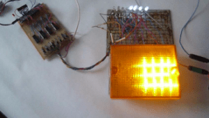
Photo at work.


A good experiment turned out to be with this weekend design. It was interesting
All those who have seen a more or less modern car not for the second time, and even if it was a matter of driving, have long noted for themselves one of the useful options... People call it a lazy turn signal or a polite turn signal. Its whole essence boils down to the fact that when turning right or left, the driver only touches the turn signal lever once, without fixing it. That is, it simply makes the turn signal circuits work, but does not turn on this very switch. As a result, after the lever is released, the direction indicators are activated 3-4 more times, and at this time the driver can already go about his “business,” that is, completely devote himself to the road. The option is very useful when you have to change lanes. After all, when the turn signal lever is fully turned on, automatic shutdown will not occur, due to the insignificant angle of rotation of the steering wheel, which means you will have to poke back and forth with the pointer itself or constantly support it with your hand on the verge of turning on in order to imitate the operation of the turn signal. And if there is such an option, then I just slightly touched the lever and forgot. In general, we think that the essence of the work has been fully revealed, but now it’s worth mentioning the possibility of implementing such an option on your machine.
For which electrical circuits is a polite turn signal on Arduino suitable?
Before you go into all serious troubles about the production of a polite turn signal, you need to understand what electrical connection diagrams it will be suitable for without modifying the electrical circuit in the car.
Here we are presented with two main options that differ in principle. The first is when the turn signals turn on when they are connected as a load. That is, the switching occurs due to switching the turn signal lamp circuit, in which the turn signal lever itself is located, it is this that closes the circuit, after which the operation occurs. In this case, it will not be possible to use our option, since when the lever opens the circuit with the lamps, we immediately disable the possibility of light indication, even if a signal arrives at the lever itself, it simply will not go any further.
The second option is ours, when there are control signals and there are output power signals. In this case, instead of the standard relay, you can install exactly the circuit that we would like to bring to your attention.

Relay power module that can be purchased on the Internet to control the power load

Sketch and circuit of a lazy (polite) turn signal on Arduino
So, one can argue about using Arduino as a head unit for lazy turn signals, since this is also not an entirely ideal solution, which has its drawbacks. For example, it will be necessary to have constant power after turning on the ignition; in order to ensure performance, it will be necessary to connect power circuits. At the same time, the harness itself from extra radio components is basically useless here, because in this case you can simply program a microcontroller and use only it. But this minus is also a plus, because anyone who has one can program Arduino, and for microcontrollers you will also need a programmer.
Writing a program will be one of the most difficult tasks. Here a beginner will have to spend more than one hour of his free time and study the work of algorithms, but fortunately there is the Internet and there is us. So here's the sketch.
Int switchPinR=8; int switchPinL=7; int ledPinR=11; int ledPinL=12; boolean ledOn = false; int i=0; int z=0; void setup() ( // put your setup code here, to run once: pinMode(switchPinR, INPUT); pinMode(switchPinL, INPUT); pinMode(ledPinR, OUTPUT); pinMode(ledPinL, OUTPUT); Serial.begin(9600 ); ) void loop() ( // put your main code here, to run repeatedly: //2 label: if (digitalRead(switchPinR) == HIGH && digitalRead(switchPinL) == HIGH) ( digitalWrite(ledPinR, HIGH) ; digitalWrite(ledPinL, HIGH); i=0; while (i<7) { ledOn = !ledOn; digitalWrite(ledPinR, ledOn); digitalWrite(ledPinL, ledOn); delay(400); i++; z++; if (digitalRead(switchPinL) == LOW && digitalRead(switchPinR) == LOW && z>=7) ( break; ) ) ) else ( digitalWrite(ledPinR, LOW); digitalWrite(ledPinL, LOW); z=0; ) //cycling the emergency signal if (digitalRead(switchPinR) == HIGH && digitalRead(switchPinL) == HIGH) (goto label;) //Right turn signal. if (digitalRead(switchPinR) == HIGH) ( digitalWrite(ledPinR, HIGH); i=0; while (i<7) { ledOn = !ledOn; digitalWrite(ledPinR, ledOn); delay(400); i++; z++; if (digitalRead(switchPinR) == LOW && z>=7) ( break; ) ) ) else ( digitalWrite(ledPinR, LOW); z=0; ) //Left turn signal. if (digitalRead(switchPinL) == HIGH) ( digitalWrite(ledPinL, HIGH); i=0; while (i<7) { ledOn = !ledOn; digitalWrite(ledPinL, ledOn); delay(400); i++; z++; if (digitalRead(switchPinL) == LOW && z>=7) ( break; ) ) ) else ( digitalWrite(ledPinL, LOW); z=0; ) ) )
To briefly summarize, the sketch has 2 inputs and 2 outputs. In this case, when a positive, that is, high-level signal is input at the input (8,7), we receive a certain number of blinks (z or i) at the corresponding output (11,12). In short, something like this. That is, if you want to change something in the sketch regarding the number of blinks and input outputs, then pay attention to these variables. If you need to change the length of blinks, then your attention should be focused on the delay function.
Another feature of the program is a somewhat unusual alarm output. First, the left and right indicators are processed, then the hazard warning lights turn on. This is due to the fact that it can only turn on if the input is high at the same time at inputs 8 and 7. And this condition will only be fulfilled in the second cycle, because pressing two buttons at once is physically impossible. The speed of the microcontroller will allow you to read the high output from a button faster and decide that this is, after all, a condition for triggering the turn signal, and not an alarm. Although you shouldn’t worry about it, unless saying thank you on the road will be problematic.
Features of connecting a lazy (polite) turn signal in a car using Arduino
You should not use pin 13 as an output, since every time you turn the power on and off, the indicators that will be connected to this output may flicker.
When moving from control signals to power signals, use appropriate blocks purchased on the Internet or assembled by yourself. We have already talked about such blocks - modules.
When receiving signal 1 from a voltage of 12 volts, place a 10 Kom resistor in front of the input.

That's all the instructions for making a lazy turn signal for a car using an Arduino microcontroller, and now about the same thing in the video...
Let's consider creating a running turn signal like on an Audi, using the example of a headlight from a Renault Clio car. Let's make turn signals and DRLs in one device.
What you will need for this: LED strip consisting of ws2812b LEDs Arduino nano controller(can be used in any other form factor) Car charger for mobile phones with USB output. Since the Arduino controller needs a voltage of 5V, we will use this charger as a voltage converter from 12V to 5V. Voltage stabilizer for 5V KR142EN5V (KREN5V) or any other imported analogue. 3 10 kOhm resistors as pull-up resistance.
Connection diagram
The Arduino controller must be connected to the car's network via a 12V -> 5V converter so that the voltage to the circuit comes from turning on the ignition. You need to connect the positive wire from the existing turn signal to the KREN5V voltage stabilizer. This article discusses the connection and firmware of only one turn signal; to make a second turn signal, you need to similarly connect the second LED strip to any free digital output of the Arduino (for example 7), and also add code for it in the firmware according to our example.
Controller firmware
To work with pixel LEDs you will need a library
#include
// connect the library
Adafruit_NeoPixel strip = Adafruit_NeoPixel(22, 8, NEO_GRB + NEO_KHZ800);
int t,t1,t2,t3,t4,p2,p1 = 0;//time variable
void setup() (
pinMode(2, INPUT);
pinMode(3, INPUT);
pinMode(4, INPUT);
digitalWrite(2, LOW);
digitalWrite(3, LOW);
digitalWrite(4, LOW);strip.begin();
strip.show();}
void loop() (
if (digitalRead(2) == LOW) ( //If the turn signal is off
for(int i = 0; i< 23; i++) {
strip.setPixelColor(i, strip.Color(255,255,255)); // R=255, G=255, B=255 - white color of the LED, when turned on we turn on the running lights
}
strip.show();
}if ((digitalRead(2) == HIGH) & (t == 1)) ( // check if the turn signal is on
for(int i = 0; i< 23; i++) {
strip.setPixelColor(i, strip.Color(0, 0, 0)); // extinguish all diodes
}
strip.show();
for(int k = 0; k< 3; k++){ // цикл до трех - сигнал «перестроения» , при кратковременном включении мигает 3 раза,for(int i = 0; i< 23; i++){
if (digitalRead(2) == HIGH) (k = 0;) // if while the turn signal is blinking we receive another positive signal, then reset the counter so that the turn signal blinks at least 3 more times
strip.setPixelColor(i, strip.Color(255, 69, 0)); // R=255, G=69, B=0 - LED colordelay((t4)/22);
strip.show();}
if (digitalRead(2) == HIGH) (t4=t4+20;) // if all the diodes are lit yellow, but the signal from the relay is still coming, then we increase the burning time
if (digitalRead(2) == LOW) (t4=t4-20;) // if all the diodes are lit yellow, but the signal from the relay is still coming, then we increase the burning timefor(int i = 0; i< 23; i++){
strip.setPixelColor(i, strip.Color(0, 0, 0)); // R=0, G=0, B=0 - LED color
delay((t3)/22);
strip.show();}
if ((digitalRead(2) == LOW)) (t3=t3+20;)
if ((digitalRead(2) == HIGH)) (t3=t3-20;)
}if ((digitalRead(2) == HIGH) & (t == 0)) ( // check if the turn signal is on
t1 = millis(); //remember what time you turned on
for(int i = 0; i< 22; i++) {
strip.setPixelColor(i, strip.Color(255, 69, 0)); // when you turn on the turn signal for the first time, turn on all the diodes yellow
}
strip.show();
while (digitalRead(2) == HIGH) ()
t2 = millis(); // remember what time the turn signal turned off
t4=t2-t1;for(int i = 0; i< 22; i++) {
strip.setPixelColor(i, strip.Color(0, 0, 0)); // extinguish the diodes when the signal from the turn relay disappears
}
strip.show();
while (digitalRead(2) == LOW) (
if ((millis()-t2)>2000)(break;)
}
if ((millis()-t2)<2000) {
t3 = millis()-t2; // time for which the turn signals go off
t = 1; // flag, we know that the time value has been saved.
}
}if (digitalRead(4) == HIGH) ( //special signals
for(int j = 0; j< 16; j++) {
for(int i = 0; i< 22; i++) {
strip.setPixelColor(i, strip.Color(255, 0, 0)); // R=255, G=0, B=0 - LED color
}
strip.show();
delay(20);
for(int i = 0; i< 22; i++){
}
strip.show();
delay(20);
}for(int j = 0; j< 16; j++) {
for(int i = 0; i< 22; i++) {
strip.setPixelColor(i, strip.Color(0, 0, 255)); // R=0, G=0, B=255 - LED color
}
strip.show();
delay(20);
for(int i = 0; i< 22; i++){
strip.setPixelColor(i, strip.Color(0, 0, 0)); // R=0, G=0, B=0 - LED color
}
strip.show();
delay(20);
}
}if (digitalRead(3) == HIGH) ( //strobe
for(int j = 0; j< 24; j++) {
for(int i = 0; i< 22; i++) {
strip.setPixelColor(i, strip.Color(255, 255, 255)); // R=255, G=255, B=255 - LED color
}
strip.show();delay(15);
for(int i = 0; i< 22; i++){
strip.setPixelColor(i, strip.Color(0, 0, 0)); // R=0, G=0, B=0 - LED color
}
strip.show();
delay(15);
}
delay(500);
Do the same for the code for the second turn signal.
Video of how our headlight works
The designer of running lights from Aliexpress is a printed circuit board and a set of radio components. All you need to do is solder the components onto the board.
But you can get more interesting effects of running lights from it. For example, for car turn signals or brake lights, or just for garlands for a holiday.

This circuit can operate in the supply voltage range of 3 -15 Volts. The pulse generator is assembled on the NE555 chip, then the pulses are sent to a decimal counter with a decoder - a CD4017 (or K561IE8) chip, to the outputs of which LEDs are connected through current-limiting resistors.
The switching speed of the running lights is regulated by a trimming resistor. Add a circuit with triggers and output transistor switches. No need to program anything, etc. As a result, you can get more interesting lighting effects of running lights. We need to make another printed circuit board with K561TM2 triggers and KT815 power switches. A pulse from each K561IE8 output is fed to the trigger input using the “latch” principle, that is, at the trigger output the signal remains constant until the reset pulse arrives from pin 11 of the CD4017(K561IE8) chip. 9 channels are switched on per cycle.